


Abstract
Highly deformable adhesive materials are increasingly employed in engineering applications where flexibility, energy dissipation and damage tolerance are required. The mechanical characterisation of these materials, however, presents significant challenges due to their pronounced non-linear behaviour, large deformations, and, in many cases, time-dependent effects. This paper provides a critical review of experimental, constitutive and numerical approaches used for the characterisation of highly deformable adhesive materials, considered here as bulk materials independently of a specific joint configuration. The review covers mechanical testing methods under large strains, hyperelastic and visco-hyperelastic constitutive models, and the application of fracture mechanics concepts and numerical techniques as exploratory tools for material analysis and comparison. Particular attention is given to the capabilities and limitations of the different approaches, their domains of applicability and the assumptions involved in their use. By highlighting current practices, open challenges and recent developments, this work aims to support the selection of appropriate characterisation methodologies and modelling strategies for highly deformable adhesive materials.
1. Introduction
Adhesive bonds are increasingly being used in various industrial applications, replacing traditional joining methods and offering new possibilities. Highly deformable adhesive materials are increasingly employed in engineering applications where flexibility, energy dissipation and damage tolerance are required; for example, in demanding aerospace, automotive and construction applications [1,2,3]. In particular, the automotive industry is paying considerable attention to the use of flexible adhesive materials in applications involving engineering. Many properties give these bonds an advantage over other methods, such as flexibility, the ability to isolate from vibration, a greater ability to transfer forces between joints as a continuous bond, a reduction in the weight of assemblies and the ability to join materials of different natures, as well as high sealing capabilities [4].
Adhesives can be used in a wide range of applications, and we can find very different characteristics in all the types available on the market. For example, some formulations exhibit a stiff mechanical behaviour with limited deformability, allowing efficient load transfer but often showing brittle responses. On the other hand, highly deformable adhesive materials present ductile behaviour, with enhanced capacity for energy dissipation and improved resistance to shock and vibration.
Adhesives can be classified according to their mechanical behaviour [5]. A summary of typical adhesive families and their general performance characteristics is provided in Table 1. Rigid adhesives include anaerobics, cyanoacrylates and epoxies. Tenacious adhesives include toughened anaerobics, toughened cyanoacrylates, acrylics, UV-curable adhesives and toughened epoxies. Flexible adhesives include silicones, polyurethanes and modified silanes.
Table 1.
Types of adhesives according to their performance.
Despite the wide range of potential applications for highly deformable adhesive materials, their use is still rather limited compared to other bonding systems. In recent years, several lines of research have been opened to study the mechanical behaviour of adhesive materials in more detail, with the aim of improving their understanding and broadening their range of applicability. However, the study of adhesive behaviour is complex and depends on several factors such as environmental conditions, temperature, loading history, amount of previous deformation and the type of stress to which the adhesive is subjected [6]. In addition, the final properties of each adhesive can vary depending on several parameters related to its processing and application, making it even more complex.
In this review, the term “adhesive materials” is used to refer specifically to highly deformable polymeric materials commonly employed in adhesive formulations, considered here as bulk materials characterised independently of a specific joint configuration. The scope of the present work is therefore limited to the experimental, constitutive and numerical characterisation of such materials under large deformations, with the aim of identifying suitable testing methodologies, modelling strategies and analysis tools. The behaviour of complete adhesive joints, which is strongly influenced by factors such as adherend properties, joint geometry, confinement effects, curing conditions and interfacial phenomena, is outside the scope of this review and is not addressed in detail. Consequently, the fracture mechanics approaches and numerical techniques discussed herein are presented as exploratory and comparative tools for material characterisation, rather than as direct predictors of the mechanical performance or failure of real bonded joints.
This is the motivation behind the line of research in which this work is framed, which aims to provide a consolidated and critical understanding of the mechanical behaviour of highly deformable adhesive materials, with particular emphasis on hyperelastic formulations and on the methodologies used for their characterisation and modelling.
These days, the Finite Element Method (FEM) is a standard numerical tool in solid and structural mechanics in general [7]. Most analyses carried out in engineering practice are still based on the solution of static linear problems, where the applied load does not vary as a function of time and a linear relationship between force and deformation (Hooke’s law) is assumed, requiring the determination of a limited number of material properties. However, the modelling of non-linear, time-dependent and strain-rate-dependent behaviour, which represented a major challenge until a few years ago, has become increasingly feasible thanks to advances in computing power and numerical algorithms. As a result, FEM is now widely used as a support tool for the analysis and interpretation of the mechanical behaviour of materials exhibiting pronounced non-linearity.
This is particularly relevant for highly deformable adhesive materials, which tend to exhibit hyperelastic and, in many cases, visco-hyperelastic behaviour. Due to their mechanical complexity, numerical simulation has become an indispensable complement to experimental characterisation in the study of these materials.
Considering the growing interest in highly deformable adhesive materials and the increasing role of numerical simulation in their mechanical analysis, this review aims to provide a consolidated overview of current approaches used for the characterisation of adhesive materials with hyperelastic behaviour.
The objective of this work is to identify and critically analyse experimental, constitutive and numerical techniques currently employed for the characterisation of materials with non-linear behaviour, with particular emphasis on the mechanical and fracture-related properties of highly deformable adhesive materials considered as bulk materials.
To achieve this objective, a review of existing methods and previously published studies by different authors is presented, with the aim of providing a global view of the current state of the art in the characterisation of highly deformable adhesive materials from different perspectives.
After an initial literature survey, only a limited number of previous works were found to be specifically dedicated to the study of hyperelastic adhesive materials exhibiting viscous effects.
On the other hand, due to the strong similarities between the mechanical behaviour of highly deformable adhesive materials and elastomers, relevant studies on rubber-like materials, natural latex, tyre treads and related systems were also considered in this review.
2. Behaviour of Hyperelastic Adhesives
Adhesives with hyperelastic behaviour, mainly derived from polyurethanes, are polymeric materials that exhibit elastic and sometimes viscous behaviour [8]. These materials exhibit rubber-like properties, resulting in high reversible deformations without fracture (in some cases up to 500% deformation), high damping properties, durability and hysteresis under cyclic loading. These properties are desirable in various applications, especially their large non-linear elastic deformation, which is what leads to their classification as hyperelastic materials [9,10].
The behaviour of this material is complex to study; the deformations do not have a linear behaviour with respect to the load that generates them, making it difficult to define a function or expression that is capable of directly relating the stress to the deformation, as is usual in linear materials [11]. In their stress–strain curve, different sections of Figure 1 are usually distinguished [12]:
Figure 1.
Schematic representation of linear elastic and hyperelastic stress strain behaviour. The linear response is characterised by a constant slope (E0), whereas the hyperelastic response exhibits a non-linear increase of stress with strain. Arrows indicate the loading and unloading paths.
- Small deformations will behave like a classical elastic material, in a linear way.
- Given strain, the curve abandons the hypothesis of small deformations and becomes non-linear. The slope of the curve flattens out and will be able to deform to a large extent with little increase in stress.
- Eventually, the slope increases again, and the stress increases rapidly.
Adhesives with this hyperelastic behaviour do not behave as such over the entire deformation spectrum; only after a certain degree of deformation, which is different for each adhesive, do they begin to change from a linear to a non-linear state. The determination of this transition point will be of great interest when characterising their behaviour. On the one hand, hyperelastic models describe a behaviour close to that of incompressible materials.
On the other hand, some of these adhesives can exhibit viscoelastic effects, a combination of pure elastic behaviour together with the influence of viscosity [13]. These materials can undergo significant softening during the initial loading cycles, after which the behaviour stabilises and becomes repeatable. This phenomenon is known as the Mullins effect and will be discussed later in the context of visco-hyperelastic characterisation (see Figure 2).
Figure 2.
Schematic representation of a cyclic stress–strain response illustrating the Mullins effect in rubber-like materials. Successive loading–unloading cycles exhibit stress softening and a dependence on the maximum previously applied strain. Arrows indicate the loading and unloading paths: (a) initial loading, (b) first unloading, (c) reloading up to the previous maximum strain, (d) subsequent unloading, and (e) loading to a new maximum strain. Points A and B denote intermediate and maximum strain states reached during the cycles.
3. Mechanical Characterisation of Highly Deformable Adhesive Materials
3.1. Mechanical Characterisation
The development of what is now a solid knowledge base on the mechanics of hyperelastic materials began in the early 1940s, when Mooney, through uniaxial tensile experiments on soft rubber materials, observed that neither the force–strain relationship nor the stress–strain response conformed to Hooke’s law [14]. It was therefore concluded that linear elasticity was inadequate to describe the mechanical response of elastomeric materials, which led to the formulation of the non-linear theory of elasticity.
Both hyperelasticity and linear elasticity are reversible processes, in the sense that no permanent deformation is assumed in their constitutive description, and the work performed during loading is fully recovered upon unloading. The derivation of the stress–strain relationship for hyperelastic materials is based on a potential function known as the Helmholtz free energy per unit volume, Ψ [15], also referred to as the strain energy density or elastic potential. This scalar-valued function relates the strain energy to the reference volume and, in turn, to the state of deformation. A defining characteristic of hyperelastic materials is that the strain energy density depends only on the current strain state and not on the deformation history [16].
Over the years, numerous constitutive models have been proposed to describe the mechanical behaviour of hyperelastic materials. Depending on the underlying formulation strategy, these models are commonly classified as either phenomenological or micromechanical. Phenomenological models are derived from experimental observations of rubber-like materials subjected to different homogeneous deformation modes and rely on fitting mathematical expressions to experimental data [17]. These formulations are often expressed in polynomial form and may be based on strain invariants, principal stretches, or combinations of both.
Micromechanical models, on the other hand, exploit concepts from statistical mechanics to represent the material behaviour at the microscopic level while reproducing the macroscopic response. It is worth noting that phenomenological models account for a large proportion of the hyperelastic formulations reported in the literature, particularly in engineering-oriented material characterisation studies [18].
The formulation of models capable of adequately representing the mechanical response of hyperelastic materials over a wide range of deformation modes remains a central objective in this field. In this context, model performance is often assessed based on its ability to reproduce experimental data obtained under uniaxial tension, biaxial tension and pure shear loading conditions [19]. The experimental data reported by Treloar [20] have long served as a benchmark for evaluating the predictive capabilities of new constitutive formulations across these loading modes.
Key challenges in hyperelastic material modelling include balancing predictive capability with model complexity, particularly with respect to the number of material parameters required. Many models can provide accurate representations under a single loading mode, such as uniaxial tension, but perform poorly when extrapolated to other deformation states. Conversely, more complex models may require a large number of parameters that are difficult to identify experimentally and involve significant testing effort. From a practical characterisation perspective, the selection of a constitutive model is therefore guided by several factors, including the strain range of interest, the quality and availability of experimental data, the ease of parameter identification and the intended use of the model within a broader characterisation framework.
3.2. Experimental Trials
In general, two factors are commonly considered when defining the practical scope of a hyperelastic constitutive model. The first is the ability of the model to adequately reproduce experimental data obtained under different deformation modes, such as uniaxial tension, equibiaxial tension and pure shear. The second factor is the number of material parameters required by the model, since an increasing number of parameters generally implies a greater experimental effort for parameter identification and calibration.
Several experimental tests are therefore required to define the input data used for hyperelastic model calibration. In practice, the most reliable identification of hyperelastic parameters is often achieved by combining experimental data from different deformation modes [21] rather than relying on a single test configuration.
The most commonly employed experimental tests for hyperelastic material characterisation are summarised below.
3.2.1. Uniaxial Stress
Uniaxial tensile testing is one of the most widely used experimental methods for characterising materials with hyperelastic behaviour. To ensure a predominantly uniaxial strain state, the specimen geometry should exhibit a length that is large compared to its width and thickness, allowing deformation to occur with minimal lateral constraint and thinning [22,23]. For large deformations, the principal stretches can be expressed as
and the corresponding principal stresses as
Experimental studies indicate that the specimen length should be at least ten times greater than its width and thickness in order to minimise end effects [23]. As the objective of this test is material characterisation rather than specimen failure, the use of dog-bone-shaped specimens is not strictly required, although such geometries are commonly adopted to reduce stress concentrations near the grips. According to ISO 37:2005 [24], the most frequently used specimen geometry is shown in Figure 3.
Figure 3.
Uniaxial tension test specimen.
In accordance with standard recommendations, strain should be measured in the central, narrow region of the specimen, where a nearly homogeneous tensile state develops. This typically requires the use of non-contact measurement techniques, such as digital image correlation (DIC) or laser extensometry [25,26].
3.2.2. Pure Shear
Although the pure shear test may resemble a simple tensile test at first glance, its primary objective is to establish a planar stress state within the specimen. Achieving this condition requires careful selection of specimen geometry, as discussed in [23,27,28,29,30]. Typically, the specimen width is chosen to be much larger than the dimension along the loading direction, while maintaining a relatively small thickness.
This configuration constrains lateral deformation, so that most of the specimen thinning occurs in the thickness direction, thereby promoting a pure shear state in the central region.
The principal stretches for this deformation mode are given by
and the corresponding principal stresses as
The pure shear configuration shown in Figure 4 is one of the most commonly adopted geometries for planar stress testing.
Figure 4.
Planar shear test specimen and test configuration. The upper clamp is fixed and a vertical displacement is imposed on the lower clamp. The corresponding reaction force F is recorded. Arrows indicate the loading direction and reaction forces.
For incompressible materials, a state of pure shear develops in the specimen at an angle of approximately 45° with respect to the loading direction. As in the uniaxial case, non-contact strain measurement techniques are recommended to accurately capture deformation in the central region of the specimen.
3.2.3. Biaxial Tension
For incompressible or nearly incompressible materials, equibiaxial tension provides a deformation state that is equivalent, from a kinematic standpoint, to compression. Direct compression testing is often experimentally challenging due to friction effects between the specimen and the loading platens, which restrict lateral expansion. Although equibiaxial testing is more complex to implement, it allows more uniform deformation states to be achieved and can therefore improve the accuracy of material parameter identification [23,31,32].
Equibiaxial deformation is typically achieved by radially stretching a circular specimen, as illustrated in Figure 5. In this configuration, the specimen is subjected simultaneously to two identical principal stresses.
Figure 5.
Cruciform specimen geometry and equibiaxial tension test rig. The specimen is clamped along its four arms and subjected to imposed displacement in two orthogonal directions, generating an equibiaxial tensile stress state in the central region. The arrows indicate the loading directions and the corresponding applied forces F.
The principal stretches and stresses for equibiaxial tension are given by
As in the previous tests, non-contact measurement techniques are required to ensure accurate strain measurement in the central region of the specimen.
3.3. Hyperelastic Models
As numerical simulations are increasingly becoming an integral part of the mechanical analysis and interpretation of material behaviour, engineers are constantly faced with the challenge of choosing an appropriate hyperelastic constitutive model, as this choice strongly influences the quality and reliability of numerical results. Rather than seeking a universally “best” model, it is therefore useful to analyse how the different hyperelastic formulations reviewed in this study perform in representing experimental data, as well as to identify their respective differences, overlaps and domains of applicability.
There is no single, well-defined methodology for classifying hyperelastic models. Different criteria have been proposed in the literature, depending on the intended application and the type of experimental data considered. For instance, Marckmann and Verron [19] ranked 20 hyperelastic models based on their ability to reproduce classical experimental data sets reported by Treloar [20] and Kawabata [33], highlighting the strong dependence of model performance on deformation mode and strain range.
In the following, attention is focused on hyperelastic models in which a phenomenological mathematical framework is constructed to characterise the mechanical behaviour of rubber-like materials, without explicitly accounting for their microscopic or molecular structure. These approaches do not establish a direct physical link with the underlying deformation mechanisms, but instead rely on fitting experimental stress–strain data obtained under one or more deformation modes. The identified material parameters are then used to extrapolate the material response to more complex deformation states, an approach that remains widely adopted in practical material characterisation.
The elastic strain energy per unit volume (W) is dependent on the strain [34]:
where B is the left Cauchy–Green deformation tensor, defined as and F is the deformation gradient tensor, given by F = ∂xi/∂Xi. Here, xi and Xi denote the components of the displacement vector in the deformed and undeformed configurations, respectively.
Using the principal stretches λi, defined as the unit extensions , the deformation state can be fully described and the strain energy density function may be expressed either in terms of the principal stretches:
or as a function of the deformation invariants:
where the principal stretch is defined as
and the deformation invariants are given by
In practice, many highly deformable polymeric materials exhibit an approximately incompressible behaviour under large strains, which can be expressed by assuming a constant volume condition, i.e., = 1 [35].
Table 2 provides a comparative overview of the most commonly used hyperelastic constitutive models reported in the literature, highlighting their main characteristics, advantages and limitations when applied to the characterisation of highly deformable adhesive materials. While the following subsections focus on a selection of widely adopted phenomenological models, the table also includes additional formulations that are frequently cited in comparative studies and implemented in commercial numerical codes, in order to provide a broader and more complete perspective of available modelling approaches.
Table 2.
Comparative overview of hyperelastic constitutive models used for highly deformable adhesive materials.
3.3.1. Polynomial Models
A general class of hyperelastic formulations based on strain invariants was originally developed by Rivlin, who proposed expressing the strain energy density function in polynomial form [36]:
For materials that can be reasonably considered incompressible, the volumetric contribution vanishes (I3 = 1), and the strain energy function reduces to
where N is the polynomial order, Cij are material parameters, and I1 and I2 are the first and second invariants of the deviatoric deformation.
3.3.2. Mooney–Rivlin Model
The Mooney–Rivlin model represents a particular case of the polynomial formulation. The classical two-parameter form proposed by Mooney and Rivlin is given by [14,37]
It should be noted that extended versions of the Mooney–Rivlin model including additional parameters have been proposed to improve fitting accuracy, at the expense of increased model complexity and parameter identification effort.
3.3.3. Neo-Hookean Model
By retaining only the first term of the Mooney–Rivlin formulation, the Neo-Hookean model is obtained [9]:
This is one of the simplest hyperelastic models and can provide an adequate approximation for relatively small to moderate deformations, although its predictive capability rapidly deteriorates at larger strain levels.
3.3.4. Yeoh Model
Yeoh [38,39] proposed a hyperelastic model based solely on the first strain invariant, expressed as
A distinctive feature of this formulation is that the shear modulus varies with strain while depending only on the first invariant. The Yeoh model was originally developed to capture stress–strain behaviour under different deformation modes, particularly in cases where shear deformations play a dominant role, such as in tyre applications.
3.3.5. Ogden Model
The Ogden model, originally formulated in 1972 [40], is a versatile hyperelastic formulation capable of describing the mechanical behaviour of a wide range of rubber-like materials. The strain energy density function is expressed in terms of the principal stretches and can be written in several equivalent forms. One commonly adopted expression, reported by Bergström [41], is
where N is the order of the model and μn and αn are material parameters.
As summarised in Table 2, no single hyperelastic model can be considered universally suitable for the characterisation of highly deformable adhesive materials. Simpler formulations, such as Neo-Hookean or low-order Mooney–Rivlin models, may provide acceptable representations at small to moderate strains but fail to capture the pronounced non-linearity typically observed at large deformations. More flexible models, such as Ogden-type formulations, offer improved accuracy over extended strain ranges but require careful parameter identification and high-quality experimental data. Models incorporating physical constraints, such as Arruda–Boyce or Gent formulations, are particularly relevant for materials exhibiting strain-stiffening effects, although their applicability may be limited by assumptions of molecular network behaviour. Consequently, the selection of an appropriate hyperelastic model should be guided by the intended strain range, available experimental data and the specific objectives of the material characterisation.
3.4. Visco-Hyperelastic Characterisation of Highly Deformable Adhesive Materials
Highly deformable adhesive materials often exhibit a mechanical response that cannot be adequately described by purely hyperelastic formulations. In addition to pronounced non-linear elasticity and large deformations, these materials commonly show time-dependent and history-dependent effects, such as rate sensitivity, hysteresis, stress relaxation and stress softening [13,41,42]. Recent experimental and numerical studies on hyperelastic adhesive systems have further highlighted the relevance of visco-hyperelastic effects under large deformations and elevated temperatures, emphasising the need for combined modelling and experimental validation approaches [43]. The combined presence of elastic and viscous mechanisms motivates the use of visco-hyperelastic frameworks for their mechanical characterisation.
From a material characterisation perspective, visco-hyperelastic approaches aim to capture the influence of loading history and time-dependent effects on the stress–strain response, rather than to provide direct predictions of the long-term performance of bonded joints. These models are therefore primarily used to interpret experimental data, compare material formulations and identify parameters relevant to the mechanical behaviour of highly deformable adhesive materials under different loading conditions.
Among the various history-dependent phenomena observed in rubber-like and highly deformable polymeric materials, the Mullins effect, also referred to as stress softening [44,45,46,47,48,49,50,51], plays a particularly important role (see Figure 5). This effect is characterised by a reduction in stiffness during subsequent loading cycles following an initial deformation, leading to a marked dependence of the mechanical response on the maximum previously applied strain. The Mullins effect is typically observed under cyclic loading and is strongly influenced by factors such as strain amplitude, loading rate and material formulation, as demonstrated in recent experimental investigations on highly deformable polymer systems [48].
From an experimental point of view, the Mullins [44] effect is commonly identified through cyclic tensile or shear tests, where successive loading–unloading cycles reveal progressive changes in the stress–strain response. For highly deformable adhesive materials, this phenomenon is especially relevant during material characterisation, as it affects the repeatability of mechanical tests and the identification of constitutive parameters. Consequently, appropriate preconditioning procedures and loading protocols are often required to obtain consistent and representative material data.
Several constitutive approaches have been proposed in the literature to account for the Mullins effect within a visco-hyperelastic framework. Among these, pseudo-elastic formulations have been widely adopted to represent stress softening in filled rubbers, notably the model introduced by Ogden and Roxburgh [49], which provides a phenomenological description based on internal damage-like variables. More recent developments have extended this framework to incorporate additional features such as permanent set and induced anisotropy, improving its capability to capture complex cyclic responses [51]. These approaches typically introduce internal variables or damage-like parameters that evolve with deformation history, allowing the stress softening behaviour to be reproduced in a phenomenological manner. While such models can significantly improve the agreement between experimental data and numerical simulations, their parameters are often strongly dependent on the chosen loading paths and test conditions, which limits their direct transferability.
In addition to stress softening, other time-dependent effects such as strain-rate sensitivity, hysteresis and stress relaxation are frequently observed in highly deformable adhesive materials [13]. Recent work by Neto et al. has emphasised how creep responses can significantly influence the fracture and mechanical performance of adhesive systems under sustained loading conditions [52]. These phenomena further highlight the importance of considering visco-hyperelastic behaviour during material characterisation, particularly when experimental data are obtained under different loading rates or sustained deformation levels. However, it should be noted that the incorporation of viscous effects inevitably increases model complexity and the effort required for parameter identification.
Overall, visco-hyperelastic characterisation provides a valuable framework for describing the complex mechanical behaviour of highly deformable adhesive materials, especially when cyclic or time-dependent loading conditions are involved. Nevertheless, the applicability of the resulting models should be interpreted with caution and within the context of material characterisation, as their use for the prediction of the mechanical response of complete adhesive joints requires additional considerations beyond the scope of this review.
4. Fracture Characterisation Approaches for Highly Deformable Adhesive Materials
The fracture behaviour of highly deformable adhesive materials presents specific challenges that distinguish it from classical fracture problems in rigid or brittle solids. Large deformations, pronounced non-linear elasticity, time-dependent effects and complex damage mechanisms [53] make the direct application of traditional fracture mechanics concepts non-trivial. In this context, fracture-related experimental methods and modelling approaches are primarily employed as tools for material characterisation and comparison, rather than as direct predictors of crack initiation or failure in real adhesive joints. The present section reviews the main experimental and numerical approaches reported in the literature to investigate fracture phenomena in highly deformable adhesive materials, with particular emphasis on their capabilities, limitations and underlying assumptions.
Fracture mechanics distinguishes between three failure modes that are fundamental to crack propagation in solids [54,55], known as Mode I, Mode II and Mode III [56]. These modes provide a useful framework for classifying loading conditions in fracture tests, even though their applicability to highly deformable materials may be influenced by large-scale non-linear deformation and dissipation mechanisms.
Of the three independent failure modes, Mode I is often considered the most critical in experimental characterisation, as the associated fracture energy is generally lower than that corresponding to Mode II and Mode III. For this reason, the Mode I and Mode II loading configurations are most commonly adopted in fracture studies of polymeric adhesive materials, while Mode III is less frequently investigated.
The test most commonly used to study Mode I fracture behaviour is the Double Cantilever Beam (DCB) configuration, shown in Figure 6a [57], which allows for the investigation of crack initiation and propagation under controlled opening conditions.
Figure 6.
Schematic representation of fracture test configurations: (a) Mode I Double Cantilever Beam (DCB), (b) Mode II End-Notched Flexure (ENF), and (c) Mode II Single Lap Joint (SLJ). Arrows denote the direction of the applied load F, and the supports represent the boundary conditions associated with each testing setup.
Different test configurations have been proposed in the literature to investigate Mode II fracture behaviour, such as the Single Lap Joint (SLJ) configuration, shown in Figure 6c [58,59,60], and the End-Notched Flexure (ENF) specimen, shown in Figure 6b [61]. The latter is one of the most commonly used tests to obtain Mode II fracture energy in relatively brittle materials. However, for highly deformable and ductile adhesive materials, stable crack propagation may not occur in ENF specimens, which limits their applicability.
For this reason, some authors, such as Hasegawa et al. [60], have adopted SLJ-type configurations and evaluated the Mode II fracture response through energy-based parameters, such as the J-integral, which is discussed below.
In the 1920s, Griffith [62] proposed a crack growth energy criterion based on fracture mechanics theory and the rate of energy release G (20). Since then, numerous approaches have been developed to determine fracture energy in different classes of materials. For brittle materials, the compliance-based beam method (CBBM), proposed by Campilho et al. [63], has been widely adopted. This approach addresses several limitations of classical methods, such as the Corrected Beam Theory (CBT), Compliance Calibration Method (CCM) and Direct Beam Theory (DBT), which rely on accurate crack length measurement and crack tip identification, often supported by digital image processing and numerical calibration procedures [57,64,65].
In highly deformable adhesive materials, significant plasticity and non-linear deformation often develop ahead of the crack tip, which limits the applicability of linear elastic fracture mechanics concepts. For such materials, elastoplastic fracture mechanics approaches are commonly employed [55]. In this context, characteristic fracture-related parameters can be defined either in terms of the accumulated energy in the crack tip region, through the J-integral, or through kinematic measures such as the crack tip opening displacement (CTOD) [66].
The J-integral was introduced by Rice [67] to characterise fracture in non-linear elastic materials. From a physical standpoint, the J-integral represents an energy balance associated with crack growth and can be interpreted as an effective parameter describing the intensity of the crack tip field under given loading conditions. In a general form, the J-integral is defined on any contour Γ surrounding the crack front, as illustrated in Figure 7, and can be expressed as
where is the axis of propagation, is the path of integration around the crack tip, ds is the differential arc length of , T is the traction vector, U is the displacement field and W is the elastic strain energy density [68].
Figure 7.
Schematic representation of the integration contour Γ used in the definition of the J-integral around a crack tip. The arrows indicate the positive direction of contour integration, ds denote the differential arc length along Γ, n the outward unit normal vector, and X–Y the local coordinate system centred at point O.
The crack tip opening displacement (CTOD) is a parameter that reflects elastic–plastic deformation in the vicinity of the crack tip and is defined as the relative opening displacement between the crack faces at the crack tip, as illustrated in Figure 8. CTOD provides an alternative fracture-related measure, particularly relevant for materials exhibiting significant plastic deformation prior to crack growth.
Figure 8.
Schematic representation of crack tip opening displacement (CTOD) within a cohesive zone framework. The arrows indicate the crack propagation direction (Vc) and the relative opening displacement at the crack tip. The different shaded regions represent distinct mechanical zones: the inner dark region corresponds to the glassy zone near the crack tip, the intermediate shaded region to the viscous dissipation zone, and the outer light region to the rubbery zone. The separation process is illustrated at the crack tip within the cohesive region.
Wells [66] proposed that crack propagation occurs when the CTOD reaches a critical value, denoted as CTODc, which is determined experimentally. Under linear elastic conditions, CTOD can be related to the stress intensity factor as follows.
4.1. Fracture in Hyperelastic Materials
As mentioned at various points in this work, the adhesive materials considered exhibit a hyperelastic mechanical response, similar to that observed in rubber-like materials. Given the limited number of studies specifically addressing fracture characterisation in highly deformable adhesive materials, a significant part of the available literature is derived from research on elastomers and rubber. In this context, a review of fracture characterisation approaches originally developed for rubber-like materials provides valuable insight into the mechanisms and methodologies that can be adapted for highly deformable adhesive materials.
A first observation emerging from the literature is that fracture characterisation in hyperelastic materials is not always based on classical fracture modes (Mode I and Mode II). In many cases, fracture-related energy parameters are obtained directly from tensile, peel or tear tests, without explicitly enforcing a predefined fracture mode [53,69].
The fracture behaviour of highly deformable non-linear elastic materials is commonly analysed using global, energy-based approaches, considering a body containing a stationary crack of area A. The energy balance can be expressed as
where Uin is the input energy (work of external forces), U is the recoverable strain energy, and Udiss is the dissipated energy.
4.1.1. Tear Energy (Rivlin)
The first attempt to derive a tear criterion for rubber was made by Rivlin and Thomas in 1953 [70,71,72], extending Griffith’s energy-based fracture criterion to highly deformable materials. They introduced the tearing energy T, defined as the irreversible work per unit area of crack propagation, and expressed it as a function of the uniform strain energy density W0 and the crack length a:
where k(λ) is a function of the elongation ratio λ.
The two specimen geometries most commonly used for fracture testing of rubber-like materials are the stress-edge-notched tensile (SENT) specimen, shown in Figure 9a, and the pure shear (PS) specimen, shown in Figure 9b [73,74]. From a practical standpoint, SENT specimens are often preferred for material characterisation, as they can be easily manufactured from sheets and require simpler clamping conditions, whereas PS specimens typically require thicker edges and specialised fixtures to prevent slippage during testing.
Figure 9.
Schematic representation of stress-edge-notched tensile (SENT) (a) and pure shear (PS) (b) specimens. The arrows indicate the direction of the applied tensile load F and the corresponding boundary conditions. In the SENT configuration (a), the partial middle line represents the initial notch from which crack propagation is initiated under tensile loading. In the PS configuration (b), the central notch defines the crack path, while the supports and loading arrows illustrate the imposed displacement-controlled tensile deformation leading to a nominal pure shear state in the ligament region.
From Equation (24), Rivlin and Thomas derived simplified semi-empirical expressions for SENT and PS specimens, assuming materials with essentially reversible elasticity. However, most elastomers and highly deformable adhesive materials exhibit inelastic behaviour, dissipating energy through mechanisms such as viscous deformation and, in some cases, stress-induced crystallisation (e.g., natural rubber). As a result, the direct applicability of these simplified tear energy expressions is limited, and their use should be restricted to controlled characterisation scenarios [3].
4.1.2. J Integral in Non-Linear Materials
In addition to its use in elastoplastic fracture mechanics, several formulations of the J-integral have been proposed for materials exhibiting non-linear or hyperelastic behaviour. Early developments can be traced back to the work of Rivlin and Thomas, who expressed fracture-related energy parameters in terms of the uniform strain energy density of an equivalent uncracked specimen subjected to the same deformation level.
A few years later, Rice [75] formalised the J-integral framework to characterise stress and strain fields near the crack tip in non-linear elastic materials. In the context of hyperelastic materials, the J-integral is commonly interpreted as an effective, energy-based parameter suitable for comparative fracture characterisation, rather than as a strict material property.
Using SENT-type specimens, Rivlin and Thomas derived
where is the remote energy density function at the crack, is the crack length and .
For pure shear specimens, Rivlin (1953) [70] and Rice (1968) [75] proposed
which was later modified by Andrews [76] as
Hocine [77,78] introduced a further modification to account for geometrical effects specific to rubber-like materials by incorporating a function F(a/w):
Finally, Hocine [79] proposed a formulation of the J-integral for elastoplastic materials by decomposing it into elastic and plastic contributions:
A critical value JC associated with crack growth can be defined as [80]
where B is the thickness of the specimen, the area under the load curve to failure and a is the crack length.
Despite the pronounced non-linear and inelastic behaviour of most rubber-like materials, path independence of the J-integral has been verified in several experimental and numerical studies, supporting its use as a fracture characterisation parameter under controlled testing conditions [77,81,82].
4.1.3. Energy Limit Model (Volokh)
Volokh [83,84] develops a model for the fracture of hyperelastic materials based on the strain energy density, which he calls the free energy function. The free energy is the limit reached in the deformation of the material before it breaks. From this hypothesis, his formulation is developed as follows:
In this way, the hyperelastic models, already described for mechanical characterisation, can also be used to determine the fracture of the material.
The visco-hyperelastic effect is later added to this expression with the expression:
where m is a material constant that controls the sharpness and the upper incomplete gamma function. From this expression we obtain a limiting value of the failure energy with the form .
4.1.4. Crack Growth in Non-Linear Viscous Materials and the C* Integral
An important step towards the description of crack growth in non-linear viscous materials was the introduction of the C* integral by Landes and Begley (1976) [85]. The C* integral represents a boundary integral that, under appropriate conditions, is independent of the integration path, in analogy with the J-integral for non-linear elastic materials.
This framework considers a solid containing a stationary crack subjected to constant loading, where time-dependent deformation mechanisms such as primary, secondary and tertiary creep may develop. Bassani and Hawk (1990) [86] described the evolution of creep zones near the crack tip, highlighting the accumulation of deformation and energy that may eventually lead to crack growth.
The C* integral is used to characterise the growth of the creep zone ahead of the crack tip. Its application is primarily intended for the analysis of time-dependent crack tip fields and for comparative studies of material behaviour, rather than for direct prediction of crack propagation in complex structural configurations.
Crack propagation is often modelled using idealised interfacial representations, where separation occurs along a fictitious interface surface Γint. In this context, the C* integral can be evaluated along inner and outer contours, as illustrated in Figure 10 [87,88]:
where Γ denotes a contour surrounding the crack tip and the remaining terms have their usual meaning in fracture mechanics.
Figure 10.
Schematic representation of an interfacial crack model in a creeping solid. The interface surface Γint is shown along the crack plane. The inner contour Γin (blue) surrounds the crack tip region, while the outer contour Γout (red) encloses the global domain. Arrows along the contours indicate the positive integration direction. The vectors and denote the outward unit normals to the upper and lower crack faces, respectively. The coordinate system (X1, X2) defines the reference axes used in the formulation.
Despite the extensive use of fracture mechanics concepts and numerical techniques in the study of highly deformable adhesive materials, their applicability remains strongly dependent on test configuration, specimen geometry and loading conditions. Parameters obtained from fracture tests should therefore be interpreted as effective descriptors for material characterisation and comparative purposes, rather than as intrinsic properties. The direct transfer of such parameters to the prediction of crack initiation or failure in real bonded joints requires additional modelling considerations related to confinement effects, joint geometry and interfacial phenomena, which are beyond the scope of the present review.
5. Finite Element Approaches for the Characterisation of Highly Deformable Adhesive Materials
5.1. Parameter Estimation and Material Adjustments
For mechanical characterisation, finite element programmes provide a valuable support tool to interpret experimental data and reproduce the mechanical response of hyperelastic materials. These programmes often include dedicated algorithms to assist in the identification of constitutive behaviour [89]. Once a suitable hyperelastic material model has been selected, such algorithms allow the corresponding material parameters to be estimated by fitting numerical predictions to experimental data obtained from one or more of the standard tests described in Section 3.3 [90,91].
Typically, these programmes allow the quality of the fit obtained for different material models to be compared by superimposing numerical predictions and experimental curves on the same graph. For example, the graph shown in Figure 11 illustrates the stress–strain response obtained from a planar test, together with numerical results corresponding to different hyperelastic formulations (Mooney–Rivlin, Neo-Hookean, first, second and third-order Ogden, second-order polynomial of experimental data at 50 °C).
Figure 11.
Example of comparison of hyperelastic constitutive models fitted to the experimental nominal stress–strain response of SikaFlex®-252 adhesive at 50 °C [43]. The inset cuboid represents the specimen under uniaxial tension; vertical arrows denote the loading direction.
This comparison between numerical predictions and experimental data supports the selection of a constitutive model that provides an adequate representation of the observed material response over the relevant strain range. In the example shown in Figure 11, the second-order Ogden model provides a balanced fit to the planar test data along the loading direction considered.
5.2. Numerical Approaches for Fracture Analysis
Finite element methods have also been widely employed to analyse fracture-related phenomena in highly deformable adhesive materials, primarily as a means to support material characterisation and to investigate fracture processes under controlled conditions.
Crack growth is commonly associated with the degradation of load-carrying capacity in materials, and numerical approaches have been extensively explored to analyse crack propagation scenarios and energy dissipation mechanisms. In the context of the present review, such approaches are considered as tools for analysing fracture behaviour at the material level, rather than for predicting the integrity or durability of real bonded joints.
Elastic–plastic fracture mechanics (EPFM) provides a framework to analyse crack growth in materials exhibiting non-linear elastic behaviour or plastic deformation during fracture. In this context, fracture assessment is often based on the calculation of the energy release rate (ERR) [92], which depends on the stress–strain behaviour of the material and can be estimated through non-linear finite element analysis (FEA) under incremental loading conditions. Hellen and Blackburn [93] reviewed numerical techniques for evaluating the ERR within non-linear FEA, classifying them into contour integral methods and the virtual crack closure technique (VCCT). However, these techniques may exhibit numerical difficulties when large plastic zones develop or when unloading from creep-dominated states occurs [94].
5.2.1. Cohesive Zone Model
The cohesive zone model (CZM) represents an alternative numerical approach to VCCT for simulating fracture processes. It has been extensively employed to reproduce experimentally observed fracture responses in a wide range of material systems. The CZM concept was originally proposed by Barenblatt [95] for brittle materials and later extended by Dugdale [96] to perfectly plastic materials. Needleman [97] introduced traction–separation relationships in polynomial and exponential form, enabling the numerical simulation of progressive separation processes.
Following these developments, CZM-based finite element simulations have been applied to investigate fracture phenomena in various contexts, including plastic zone development near crack tips, interfacial cracking in bimaterials, delamination in composites and crack growth in polymers [98]. More recently, cohesive formulations have been extended to account for time-dependent effects, such as creep, in the fracture analysis of adhesive joints, allowing a more realistic representation of crack growth under sustained or long-term loading conditions [99].
Due to its relative simplicity and flexibility, the CZM approach has been widely adopted as a phenomenological tool to analyse fracture processes and compare different material formulations, rather than as a predictive model of failure in complex structural configurations [98,99,100,101,102]. More recently, Xu and Yuan [103] combined CZM with threshold criteria to investigate mixed-mode I/II crack behaviour within a two-dimensional extended finite element framework.
Considering that both CTOD-based and CZM-based approaches have been successfully used to analyse stable crack growth, several studies have explored possible links between these methodologies under Mode I loading conditions. For example, Li and Siegmund [104] reproduced the evolution of the crack tip opening angle (CTOA) using CZM and reported good agreement with experimental observations.
5.2.2. Modelling Using XFEM
Conventional fracture modelling techniques generally restrict crack propagation to predefined element boundaries, which may limit their applicability when the crack path is not known a priori. This limitation is particularly relevant in the analysis of complex fracture scenarios.
The extended finite element method (XFEM) overcomes this limitation by allowing crack initiation and propagation to be modelled independently of the underlying mesh topology [105,106]. In XFEM, additional enrichment functions are introduced at selected nodes, enabling discontinuities to be represented without explicit remeshing.
This capability makes XFEM a useful numerical tool for exploring crack propagation scenarios and assessing the influence of modelling assumptions on fracture responses, without requiring detailed prior knowledge of the crack path [107].
In addition to XFEM, alternative numerical strategies based on phase-field formulations have been proposed to model crack initiation and propagation in hyperelastic and highly deformable materials without prescribing the crack path in advance. These approaches treat fracture as a diffused damage process and have been successfully implemented within commercial finite element platforms such as ABAQUS®, demonstrating their capability to simulate complex fracture patterns in soft materials [108].
5.2.3. Local and Global Complex-Variable Finite Element Method
Local and global complex-variable finite element methods have been developed to calculate the energy release rate (ERR) in materials undergoing non-linear elastic deformation under both small and large strain conditions. These approaches evaluate the derivative of the strain energy with respect to crack length by introducing a virtual crack extension in the complex-variable domain.
The global complex-variable finite element method (G-ZFEM) [109] represents a general sensitivity approach capable of providing accurate ERR estimates independent of material behaviour and loading conditions. However, the duplication of degrees of freedom required by G-ZFEM leads to a significant increase in computational cost.
To improve computational efficiency, local formulations analogous to the J-integral have been proposed. The local complex-variable finite element method (L-ZFEM) restricts complex-variable calculations to a limited number of elements surrounding the crack tip, thereby reducing computational overhead.
Both G-ZFEM and L-ZFEM approaches [110] have been implemented in commercial finite element software and applied to hyperelastic fracture problems using material models such as Ramberg–Osgood, Neo-Hookean and Mooney–Rivlin formulations. The resulting energy release rate, commonly referred to as tearing energy in hyperelastic fracture analyses, has been shown to be in good agreement with analytical solutions and J-integral-based estimates.
While these methods provide powerful tools for fracture analysis and sensitivity studies at the material level, their application to component-level design requires additional considerations related to geometry, boundary conditions and material heterogeneity.
6. Conclusions and Future Lines of Action
This paper has presented a critical review of experimental, constitutive and numerical approaches used for the characterisation of highly deformable adhesive materials, considered as bulk materials independently of specific joint configurations. Particular attention has been paid to the challenges associated with large deformations, pronounced non-linear behaviour, time-dependent effects and fracture phenomena, which distinguish these materials from conventional rigid or brittle adhesives.
The review highlights that, despite the growing interest in flexible and highly deformable adhesive materials, the available literature specifically addressing their mechanical and fracture characterisation remains limited. As a result, many of the methodologies currently applied to these materials are derived from studies originally developed for rubber-like materials and elastomers. While this analogy provides valuable insight, it also introduces limitations that must be carefully considered when interpreting experimental results and modelling outcomes.
Regarding mechanical characterisation, a wide range of hyperelastic and visco-hyperelastic constitutive models have been reported in the literature. The analysis conducted in this review shows that no single model can be regarded as universally applicable. Instead, the suitability of a given formulation strongly depends on factors such as the strain range of interest, the quality and type of experimental data available, and the specific objectives of the material characterisation. Comparative approaches, combining experimental testing with numerical fitting, are therefore essential to identify appropriate modelling strategies.
In the context of fracture characterisation, it has been shown that classical fracture mechanics concepts are not always directly applicable to highly deformable adhesive materials. Energy-based approaches, including tear energy concepts, J-integral formulations and related parameters, are commonly employed as effective descriptors to analyse fracture processes under controlled conditions. However, these parameters should be interpreted as material-specific and configuration-dependent quantities, rather than intrinsic properties, and their transfer to the prediction of fracture behaviour in real bonded joints requires additional modelling considerations beyond the scope of this review.
Finite element methods play a central role in supporting the characterisation of highly deformable adhesive materials, particularly for parameter identification, sensitivity analyses and the interpretation of experimental observations. Approaches such as cohesive zone modelling, XFEM and complex-variable finite element methods provide powerful numerical tools to explore fracture scenarios and material responses. Nevertheless, their application should be regarded as exploratory and comparative in nature, and their predictive capabilities are inherently linked to modelling assumptions and test configurations.
Overall, this review provides a consolidated framework for understanding current practices, limitations and open challenges in the characterisation of highly deformable adhesive materials. Future research efforts should focus on the development of robust experimental protocols, the systematic comparison of constitutive and fracture models, and the clarification of the conditions under which methodologies derived from elastomer mechanics can be reliably applied to adhesive materials. Such advances will be essential to improve the consistency, comparability and interpretability of characterisation results for this class of materials.
Author Contributions
Conceptualization, F.J.S.P., L.F.M.d.S. and Ó.C.S.; methodology, F.J.S.P. and Ó.C.S.; formal analysis, F.J.S.P. and Ó.C.S.; investigation, F.J.S.P. and Ó.C.S.; writing—original draft preparation, F.J.S.P.; writing—review and editing, F.J.S.P. and Ó.C.S.; visualization, E.A.d.S.M.; supervision, M.S.L. and L.F.M.d.S.; project administration, M.S.L. All authors have read and agreed to the published version of the manuscript.
Funding
This research received no external funding.
Data Availability Statement
Where no new data were created.
Conflicts of Interest
The authors declare no conflict of interest.
References
- Loureiro, A.L.; Da Silva, L.F.M.; Sato, C.; Figueiredo, M.A.V. Comparison of the mechanical behaviour between stiff and flexible adhesive joints for the automotive industry. J. Adhes. 2010, 86, 765–787. [Google Scholar] [CrossRef] [Scilit]
- Burchardt, B. Advances in polyurethane structural adhesives. In Advances in Structural Adhesive Bonding; Woodhead Publishing: Cambridge, UK, 2010; pp. 35–65. [Google Scholar] [CrossRef] [Scilit]
- Dillard, D.A. Advances in Structural Adhesive Bonding; Elsevier: Amsterdam, The Netherlands, 2010; 638p. [Google Scholar]
- Dispersyn, J.; Hertelé, S.; De Waele, W.; Belis, J. Assessment of hyperelastic material models for the application of adhesive point-fixings between glass and metal. Int. J. Adhes. Adhes. 2017, 77, 102–117. [Google Scholar] [CrossRef] [Scilit]
- Maggiore, S.; Banea, M.D.; Stagnaro, P.; Luciano, G. A review of structural adhesive joints in hybrid joining processes. Polymers 2021, 13, 3961. [Google Scholar] [CrossRef] [Scilit] [PubMed]
- Viana, G.; Costa, M.; Banea, M.D.; Da Silva, L.F.M. A review on the temperature and moisture degradation of adhesive joints. Proc. Inst. Mech. Eng. Part L J. Mater. Des. Appl. 2017, 231, 488–501. [Google Scholar] [CrossRef] [Scilit]
- da Silva, L.F.M.; Campilho, R.D.S.G. Advances in numerical modelling of adhesive joints. In Advances in Numerical Modeling of Adhesive Joints; Springer: Berlin/Heidelberg, Germany, 2012; pp. 1–93. [Google Scholar] [CrossRef] [Scilit]
- Strobech, C. Polyurethane adhesives. Constr. Build. Mater. 1990, 4, 214–217. [Google Scholar] [CrossRef] [Scilit]
- Ali, A. A Review of Constitutive Models for Rubber-Like Materials. Am. J. Eng. Appl. Sci. 2010, 3, 232–239. [Google Scholar] [CrossRef] [Scilit]
- Ramezani, M.; Ripin, Z. Rubber-Pad Forming Processes: Technology and Applications; Elsevier: Amsterdam, The Netherlands, 2012. [Google Scholar]
- Parks, D.M. The virtual crack extension method for nonlinear material behavior. Comput. Methods Appl. Mech. Eng. 1977, 12, 353–364. [Google Scholar] [CrossRef] [Scilit]
- Lacarbonara, W. Nonlinear Structural Mechanics: Theory, Dynamical Phenomena and Modeling; Springer Science: Berlin/Heidelberg, Germany, 2013; pp. 1–802. ISBN 9781441912763. [Google Scholar] [CrossRef] [Scilit]
- Dal, H.; Kaliske, M. Bergström-Boyce model for nonlinear finite rubber viscoelasticity: Theoretical aspects and algorithmic treatment for the FE method. Comput. Mech. 2009, 44, 809–823. [Google Scholar] [CrossRef] [Scilit]
- Mooney, M. A theory of large elastic deformation. J. Appl. Phys. 1940, 11, 582–592. [Google Scholar] [CrossRef] [Scilit]
- Chaves, E.W.V. Notes on Continuum Mechanics; Springer Nature: Durham, NC, USA, 2013. [Google Scholar]
- Ward, I.M.; Sweeney, J. The Behaviour in the Rubber-Like State: Finite Strain Elasticity. In Mechanical Properties of Solid Polymers; Wiley-Interscience: Hoboken, NJ, USA, 2012; pp. 31–59. [Google Scholar] [CrossRef] [Scilit]
- Bahreman, M.; Darijani, H.; Fooladi, M. Constitutive modeling of isotropic hyperelastic materials using proposed phenomenological models in terms of strain invariants. Polym. Eng. Sci. 2016, 56, 299–308. [Google Scholar] [CrossRef] [Scilit]
- Steinmann, P.; Hossain, M.; Possart, G. Hyperelastic models for rubber-like materials: Consistent tangent operators and suitability for Treloar’s data. Arch. Appl. Mech. 2012, 82, 1183–1217. [Google Scholar] [CrossRef] [Scilit]
- Marckmann, G.; Verron, E. Comparison of hyperelastic models for rubber-like materials. Rubber Chem. Technol. 2006, 79, 835–858. [Google Scholar] [CrossRef] [Scilit]
- Treloar, L.R.G. Stress-Strain Data for Vulcanized Rubber under Various Types of Deformation. Rubber Chem. Technol. 1944, 17, 813–825. [Google Scholar] [CrossRef] [Scilit]
- Beda, T. An approach for hyperelastic model-building and parameters estimation a review of constitutive models. Eur. Polym. J. 2014, 50, 97–108. [Google Scholar] [CrossRef] [Scilit]
- Chiminelli, A.; Valero, C.; Lizaranzu, M.; López, C.I.; Canales, M. Modelling of bonded joints with flexible adhesives. J. Adhes. 2019, 95, 369–384. [Google Scholar] [CrossRef] [Scilit]
- Kim, B.; Lee, S.B.; Lee, J.; Cho, S.; Park, H.; Yeom, S.; Park, S.H. A comparison among Neo-Hookean model, Mooney-Rivlin model, and Ogden model for Chloroprene rubber. Int. J. Precis. Eng. Manuf. 2012, 13, 759–764. [Google Scholar] [CrossRef] [Scilit]
- ISO 37:2005; Rubber, Vulcanized or Thermoplastic—Determination of Tensile Stress-Strain Properties. ISO: Geneva, Switzerland, 2005.
- Peters, W.H.; Ranson, W.F. Digital Imaging Techniques in Experimental Stress Analysis. Opt. Eng. 1982, 21, 213427. [Google Scholar] [CrossRef] [Scilit]
- Schreier, H.; Orteu, J.J.; Sutton, M.A. Image correlation for shape, motion and deformation measurements: Basic concepts, theory and applications. In Image Correlation for Shape, Motion and Deformation Measurements: Basic Concepts, Theory and Applications; Springer Science: Berlin/Heidelberg, Germany, 2009; pp. 1–321. [Google Scholar] [CrossRef] [Scilit]
- Duncan, B.; Dean, G. Measurements and models for design with modern adhesives. Int. J. Adhes. Adhes. 2003, 23, 141–149. [Google Scholar] [CrossRef] [Scilit]
- Moreira, D.C.; Nunes, L.C.S. Comparison of simple and pure shear for an incompressible isotropic hyperelastic material under large deformation. Polym. Test. 2013, 32, 240–248. [Google Scholar] [CrossRef] [Scilit]
- Amstutz, C.; Bürgi, M.; Jousset, P. Characterisation and FE simulation of polyurethane elastic bonded joints under multiaxial loading conditions. Int. J. Adhes. Adhes. 2018, 83, 103–115. [Google Scholar] [CrossRef] [Scilit]
- Brown, R. Physical Testing of Rubber; Springer: Berlin/Heidelberg, Germany, 2006. [Google Scholar] [CrossRef] [Scilit]
- Li, S.; Liang, Y.; Li, Y. Equi-biaxial tension tests on magneto-rheological elastomers You may also like Investigation of dynamic properties of isotropic and anisotropic magnetorheological elastomers with a hybrid magnet shear test rig. Smart Mater. Struct. 2016, 25, 015015. [Google Scholar] [CrossRef] [Scilit]
- Charlton, D.J.; Yang, J.; Teh, K.K. Review of methods to characterize rubber elastic behavior for use in finite element analysis. Rubber Chem. Technol. 1994, 67, 481–503. [Google Scholar] [CrossRef] [Scilit]
- Kawabata, S.; Matsuda, M.; Tei, K.; Kawai, H. Experimental Survey of the Strain Energy Density Function of Isoprene Rubber Vulcanizate. Macromolecules 1981, 14, 154–162. [Google Scholar] [CrossRef] [Scilit]
- Rivlin, R.S. The Elasticity of Rubber. Rubber Chem. Technol. 1992, 65, 51–66. [Google Scholar] [CrossRef] [Scilit]
- Holzapfel, G.A. Nonlinear Solid Mechanics: A Continuum Approach for Engineering; Wiley: Hoboken, NJ, USA, 2000; p. 455. [Google Scholar]
- Anandan, S.; Lim, C.Y.; Anggraini, V.; Raghunandan, M.E. Numerical and Experimental Investigation of Oil Palm Shell Reinforced Rubber Composites. Polymers 2020, 12, 314. [Google Scholar] [CrossRef] [Scilit]
- Rivlin, R.S. Large elastic deformations of isotropic materials IV. further developments of the general theory. Philos. Trans. R. Soc. London. Ser. A Math. Phys. Sci. 1948, 241, 379–397. [Google Scholar] [CrossRef] [Scilit]
- Yeoh, O.H. Characterization of elastic properties of carbon-black-filled rubber vulcanizates. Rubber Chem. Technol. 1990, 63, 792–805. [Google Scholar] [CrossRef] [Scilit]
- Yeoh, O.H. Some Forms of the Strain Energy Function for Rubber. Rubber Chem. Technol. 1993, 66, 754–771. [Google Scholar] [CrossRef] [Scilit]
- Ogden, R.W. Large deformation isotropic elasticity—On the correlation of theory and experiment for incompressible rubberlike solids. Proc. R. Soc. London. A. Math. Phys. Sci. 1972, 326, 565–584. [Google Scholar] [CrossRef] [Scilit]
- Bergström, J. Mechanics of Solid Polymers: Theory and Computational Modeling; Elsevier: Amsterdam, The Netherlands, 2015. [Google Scholar] [CrossRef] [Scilit]
- Hsu, H.-H.; Tsai, J.-L. Characterizing the hyper-viscoelastic behavior of adhesive films. J. Mech. 2021, 37, 446–453. [Google Scholar] [CrossRef] [Scilit]
- Simón-Portillo, F.J.; Marques, E.A.S.; Fabra-Rodriguez, M.; da Silva, L.F.M.; Sánchez-Lozano, M. Mechanical characterisation and high temperature analysis of hyperelastic adhesives–Modelling and experimental validation. Compos. Struct. 2024, 348, 118511. [Google Scholar] [CrossRef] [Scilit]
- Mullins, L. Effect of Stretching on the Properties of Rubber. Rubber Chem. Technol. 1948, 21, 281–300. [Google Scholar] [CrossRef] [Scilit]
- Bueche, F. Molecular Basis for The Mullins Effect. Rubber Chem. Technol. 1961, 34, 493–505. [Google Scholar] [CrossRef] [Scilit]
- Bueche, F. Mullins effect and rubber–filler interaction†. J. Appl. Polym. Sci. 1961, 5, 271–281. [Google Scholar] [CrossRef] [Scilit]
- Mullins, L. Softening of Rubber by Deformation. Rubber Chem. Technol. 1969, 42, 339–362. [Google Scholar] [CrossRef] [Scilit]
- Alkhoury, K.; Ivko, R.; Hossain, M.; Nadimpalli, S.; Chester, S.A. Experiments and modeling of the coupled viscoelasticity and Mullins effect in filled rubber materials. J. Mech. Phys. Solids 2024, 188, 105650. [Google Scholar] [CrossRef] [Scilit]
- Ogden, R.W.; Roxburgh, D.G. A pseudo-elastic model for the Mullins effect in filled rubber. Proc. R. Soc. Lond. A 1999, 455, 2861–2877. [Google Scholar] [CrossRef] [Scilit]
- Zhan, L.; Qu, S.; Xiao, R. A Review on the Mullins Effect in Tough Elastomers and Gels. Acta Mech. Solida Sin. 2024, 37, 181–214. [Google Scholar] [CrossRef] [Scilit]
- Anssari-Benam, A.; Akbari, R.; Dargazany, R. Extending the theory of pseudo-elasticity to capture the permanent set and the induced anisotropy in the Mullins effect. Int. J. Non-Linear Mech. 2023, 156, 104500. [Google Scholar] [CrossRef] [Scilit]
- Neto, R.C.; Akhavan-Safar, A.; Sampaio, E.; Simões, B.; Vignoli, L.; da Silva, L. Creep behaviour of adhesively bonded joints (review). Proc. Inst. Mech. Eng. Part L J. Mater. Des. Appl. 2024, 238, 1625–1650. [Google Scholar] [CrossRef] [Scilit]
- Yang, X.; Wald, M.J.; Birringer, R.; Kemling, J.; Hedegaard, A.; Martin, J.; Clapper, J.; Long, R. Intrinsic fracture toughness of a soft viscoelastic adhesive. J. Mech. Phys. Solids 2024, 192, 105797. [Google Scholar] [CrossRef] [Scilit]
- Fineberg, J.; Gross, S.P.; Marder, M.; Swinney, H.L. Instability in dynamic fracture. Phys. Rev. Lett. 1991, 67, 457–460. [Google Scholar] [CrossRef] [Scilit] [PubMed]
- Alvarez Rodríguez, A.; Soroeta Liceras, J.; Subijana Zunzunegui, I.J.; Roldán Barbero, J.; Acale Sánchez, M.; Alcaide Fernández, J. Mecánica de Fractura; Universidad del País Vasco, Servicio Editorial: Leioa, Spain, 2002. [Google Scholar]
- Da Silva, L.F.M.; Öchsner, A. Modeling of adhesively bonded joints. In Modeling of Adhesively Bonded Joints; Springer: Berlin/Heidelberg, Germany, 2008; pp. 1–335. [Google Scholar] [CrossRef] [Scilit]
- Richter-Trummer, V.; Marques, E.A.; Chaves, F.J.P.; Tavares, J.R.M.S.; da Silva, L.F.M.; de Castro, P.M.S.T. Analysis of the Crack Growth Behavior in a Double Cantilever Beam Adhesive Fracture Test using Digital Image Processing Techniques. Mater. Und Werkst. 2011, 42, 273–281. [Google Scholar] [CrossRef] [Scilit]
- Kafkalidis, M.S.; Thouless, M.D. The Effects of Geometry and Material Properties on the Fracture of Single Lap-Shear Joints. Int. J. Solids Struct. 2002, 39, 4367–4383. [Google Scholar] [CrossRef] [Scilit]
- Niu, R.M.; Zhou, Q.C.; Chen, X.; Ju, Y.T.; Wei, Z.; Zheng, J. Experimental and numerical analysis of mode II fracture between propellant and insulation. Int. J. Adhes. Adhes. 2014, 52, 1–10. [Google Scholar] [CrossRef] [Scilit]
- Hasegawa, K.; Crocombe, A.D.; Coppuck, F.; Jewel, D.; Maher, S. Characterising bonded joints with a thick and flexible adhesive layer–Part 1: Fracture testing and behaviour. Int. J. Adhes. Adhes. 2015, 63, 124–131. [Google Scholar] [CrossRef] [Scilit]
- Carlsson, L.A.; Gillespie, J.W.; Pipes, R.B. On the Analysis and Design of the End Notched Flexure (ENF) Specimen for Mode II Testing. J. Compos. Mater. 1986, 20, 594–604. [Google Scholar] [CrossRef] [Scilit]
- Griffith, A.A. The Phenomena of Rupture and Flow in Solids. Philos. Trans. R. Soc. Lond. Ser. A 1921, 221, 163–198. [Google Scholar] [CrossRef] [Scilit]
- Campilho, R.D.S.G.; Moura, D.C.; Gonçalves, D.J.S.; Da Silva, J.F.M.G.; Banea, M.D.; Da Silva, L.F.M. Fracture toughness determination of adhesive and co-cured joints in natural fibre composites. Compos. Part B Eng. 2013, 50, 120–126. [Google Scholar] [CrossRef] [Scilit]
- Silva, M.A.L.; de Moura, M.F.S.F.; Morais, J.J. L Numerical analysis of the ENF test for mode II wood fracture. Compos. Part A Appl. Sci. Manuf. 2006, 37, 1334–1344. [Google Scholar] [CrossRef] [Scilit]
- Gálvez, P.; Carbas, R.J.C.; Campilho, R.; Abenojar, J.; Martínez, M.A.; Da Silva, L.F.M. Fracture toughness in Mode I (GIC) for ductile adhesives. J. Phys. Conf. Ser. 2017, 843, 012008. [Google Scholar] [CrossRef] [Scilit]
- Wells, A. Unstable crack propagation in metals: Cleavage and fast fracture. Crack Propag. Symp. 1961, 273, 544–553. [Google Scholar]
- Rice, J.R. A-Path-Independent-Integral-and-the-Approximate @ asmedigitalcollection. asme.org. J. Appl. Mech. Eng. 1968, 35, 379–386. [Google Scholar] [CrossRef] [Scilit]
- Ramorino, G.; Agnelli, S.; De Santis, R.; Riccò, T. Investigation of fracture resistance of natural rubber/clay nanocomposites by J-testing. Eng. Fract. Mech. 2010, 77, 1527–1536. [Google Scholar] [CrossRef] [Scilit]
- Ciavarella, M.; Papangelo, A.; McMeeking, R. Crack propagation at the interface between viscoelastic and elastic materials. Int. J. Solids Struct. 2021, 257, 108009. [Google Scholar] [CrossRef] [Scilit]
- Rivlin, R.S.; Thomas, A.G. Rupture of rubber. I. Characteristic energy for tearing. J. Polym. Sci. 1953, 10, 291–318. [Google Scholar] [CrossRef] [Scilit]
- Thomas, A.G. The Development of Fracture Mechanics for Elastomers. Rubber Chem. Technol. 1994, 67, 50–67. [Google Scholar] [CrossRef] [Scilit]
- Klüppel, M.; Huang, G.; Bandow, B. Evaluation of tearing energy of elastomer materials. KGK Kautsch. Gummi Kunststoffe 2008, 61, 656–659. [Google Scholar]
- Agnelli, S.; Balasooriya, W.; Bignotti, F.; Schrittesser, B. On the experimental measurement of fracture toughness in SENT rubber specimens. Polym. Test. 2020, 87, 106508. [Google Scholar] [CrossRef] [Scilit]
- Baranwal, A.; Agnihotri, P.K. J integral and local strain energy density approach to characterize the cracks in anisotropic hyperelastic skin type composite materials. Theor. Appl. Fract. Mech. 2022, 118, 103253. [Google Scholar] [CrossRef] [Scilit]
- Rice, J.R.; Rosengren, G.F. Plane strain deformation near a crack tip in a power-law hardening material. J. Mech. Phys. Solids 1968, 16, 1–12. [Google Scholar] [CrossRef] [Scilit]
- Andrews, E.H. A generalized theory of fracture mechanics. J. Mater. Sci. 1974, 9, 887–894. [Google Scholar] [CrossRef] [Scilit]
- Hocine, N.A.; Abdelaziz, M.N.; Ghfiri, H.; Mesmacque, G. Evaluation of the energy parameter J on rubber-like materials: Comparison between experimental and numerical results. Eng. Fract. Mech. 1996, 55, 919–933. [Google Scholar] [CrossRef] [Scilit]
- Hocine, N.A.; Abdelaziz, M.N.; Mesmacque, G. Experimental and numerical investigation on single specimen methods of determination of J in rubber materials. Int. J. Fract. 1998, 94, 321–338. [Google Scholar] [CrossRef] [Scilit]
- Hocine, N.A.; Abdelaziz, M.N.; Imad, A. Fracture problems of rubbers: J-integral estimation based upon η factors and an investigation on the strain energy density distribution as a local criterion. Int. J. Fract. 2002, 117, 1–23. [Google Scholar] [CrossRef] [Scilit]
- Kim, B.H.; Joe, C.R. Single specimen test method for determining fracture energy (Jc) of highly deformable materials. Eng. Fract. Mech. 1989, 32, 155–161. [Google Scholar] [CrossRef] [Scilit]
- Liu, H.; Lee, R.F.; Donovan, J.A. Effect of Carbon Black on the J-Integral and Strain Energy in the Crack Tip Region in a Vulcanized Natural Rubber. Rubber Chem. Technol. 1987, 60, 893–909. [Google Scholar] [CrossRef] [Scilit]
- Torabizadeh, M.; Putnam, Z.A.; Sankarasubramanian, M.; Moosbrugger, J.C.; Krishnan, S. The effects of initial crack length on fracture characterization of rubbers using the J-Integral approach. Polym. Test. 2019, 73, 327–337. [Google Scholar] [CrossRef] [Scilit]
- Volokh, K.Y. Review of the energy limiters approach to modeling failure of rubber. Rubber Chem. Technol. 2013, 86, 470–487. [Google Scholar] [CrossRef] [Scilit]
- Abu-Qbeitah, S.; Jabareen, M.; Volokh, K.Y. Quasi-static crack propagation in soft materials using the material-sink theory. Int. J. Mech. Sci. 2023, 248, 108160. [Google Scholar] [CrossRef] [Scilit]
- Landes, J.; Begley, J. A Fracture Mechanics Approach to Creep Crack Growth. Mech. Crack Growth 1976, 590, 128–148. [Google Scholar] [CrossRef] [Scilit]
- Bassani, J.L.; Hawk, D.E. Influence of damage on crack-tip fields under small-scale-creep conditions. Int. J. Fract. 1990, 42, 157–172. [Google Scholar] [CrossRef] [Scilit]
- Elmukashfi, E.; Cocks, A.C.F. A theoretical and computational framework for studying creep crack growth. Int. J. Fract. 2017, 208, 145–170. [Google Scholar] [CrossRef] [Scilit]
- Elmukashfi, E.; Kroon, M. Numerical modeling and analysis of dynamic crack propagation in rubber. In Proceedings of the 13th International Conference on Fracture 2013, ICF 2013, Beijing, China, 16–21 January 2013; Volume 5, pp. 3598–3607. [Google Scholar]
- Dassault Systèmes Simulia Corp. ABAQUS 6.14 User Documentation. 2014. Available online: http://62.108.178.35:2080/v6.14/index.html (accessed on 8 October 2025).
- Xiao, Y.; Tang, Z.; Hong, X. Inverse Parameter Identification for Hyperelastic Model of a polyurea. Polymers 2021, 13, 2253. [Google Scholar] [CrossRef] [Scilit] [PubMed]
- Chen, B.; Starman, B.; Halilovič, M.; Berglund, L.A.; Coppieters, S. Finite Element Model Updating for Material Model Calibration: A Review and Guide to Practice. Arch. Comput. Methods Eng. 2024, 32, 2035–2112. [Google Scholar] [CrossRef] [Scilit]
- Anderson, T.L. Fracture Mechanics: Fundamentals and Applications, 2nd ed.; CRC Press: Boca Raton, FL, USA, 1995. [Google Scholar]
- Hellen, T.K.; Blackburn, W.S. Non-Linear fracture mechanics and finite elements. Eng. Comput. 1987, 4, 2–14. [Google Scholar] [CrossRef] [Scilit]
- Viñuela, J.Z.; Torres, M.; Silva, R.G. Cohesive zone modeling in load–unload situations. Int. J. Mech. Sci. 2022, 222, 107205. [Google Scholar] [CrossRef] [Scilit]
- Babenblatt, G.I. The Formation of Equilibrium Cracks During Brittle Fracture. General Ideas and Hypotheses. Axially-Symmetric Cracks. J. Appl. Math. Mech. 1959, 23, 434–444. [Google Scholar] [CrossRef] [Scilit]
- Dugdale, D.S. Yielding of steel sheets containing slits. J. Mech. Phys. Solids 1960, 8, 100–104. [Google Scholar] [CrossRef] [Scilit]
- Needleman, A. A Continuum Model for Void Nucleation by Inclusion Debonding. J. Appl. Mech. 1987, 54, 525–531. [Google Scholar] [CrossRef] [Scilit]
- Jin, Z.H.; Sun, C.T. Cohesive zone modeling of interface fracture in elastic bi-materials. Eng. Fract. Mech. 2005, 72, 1805–1817. [Google Scholar] [CrossRef] [Scilit]
- Neto, R.C.; Akhavan-Safar, A.; Sampaio, E.; Assis, J.; da Silva, L. A customized shear traction separation law for cohesive zone modelling of creep loaded ENF adhesive joints. Theor. Appl. Fract. Mech. 2022, 119, 103336. [Google Scholar] [CrossRef] [Scilit]
- Needleman, A. An analysis of tensile decohesion along an interface. J. Mech. Phys. Solids 1990, 38, 289–324. [Google Scholar] [CrossRef] [Scilit]
- Xu, X.P.; Needleman, A. Numerical simulations of fast crack growth in brittle solids. J. Mech. Phys. Solids 1994, 42, 1397–1434. [Google Scholar] [CrossRef] [Scilit]
- Yan, Y.; Sumigawa, T.; Shang, F.; Kitamura, T. Cohesive zone criterion for cracking along the Cu/Si interface in nanoscale components. Eng. Fract. Mech. 2011, 78, 2935–2946. [Google Scholar] [CrossRef] [Scilit]
- Xu, Y.; Yuan, H. Applications of normal stress dominated cohesive zone models for mixed-mode crack simulation based on extended finite element methods. Eng. Fract. Mech. 2011, 78, 544–558. [Google Scholar] [CrossRef] [Scilit]
- Li, W.; Siegmund, T. An analysis of crack growth in thin-sheet metal via a cohesive zone model. Eng. Fract. Mech. 2002, 69, 2073–2093. [Google Scholar] [CrossRef] [Scilit]
- Huynh, H.D.; Tran, P.; Zhuang, X.; Nguyen-Xuan, H. An extended polygonal finite element method for large deformation fracture analysis. Eng. Fract. Mech. 2019, 209, 344–368. [Google Scholar] [CrossRef] [Scilit]
- Fries, T.P. A corrected XFEM approximation without problems in blending elements. Int. J. Numer. Methods Eng. 2008, 75, 503–532. [Google Scholar] [CrossRef] [Scilit]
- Gigliotti, L. Assessment of the applicability of XFEM in Abaqus for modeling crack growth in rubber. Sci. Rep. 2012, 2, 705. [Google Scholar]
- Zheng, S.; Huang, R.; Lin, R.; Liu, Z. A phase field solution for modelling hyperelastic material and hydrogel fracture in ABAQUS. Eng. Fract. Mech. 2022, 276, 108894. [Google Scholar] [CrossRef] [Scilit]
- Montoya, A.; Ramirez-Tamayo, D.; Millwater, H.; Kirby, M. A complex-variable virtual crack extension finite element method for elastic-plastic fracture mechanics. Eng. Fract. Mech. 2018, 202, 242–258. [Google Scholar] [CrossRef] [Scilit]
- Ytuarte, E.; Aguirre-Mesa, A.M.; Ramirez-Tamayo, D.; Avila, D.; Millwater, H.; Restrepo, D.; Montoya, A. Tearing energy calculation in hyperelastic fracture mechanics using the local and global complex-variable finite element method. Int. J. Solids Struct. 2022, 239–240, 111425. [Google Scholar] [CrossRef] [Scilit]
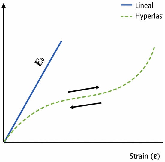
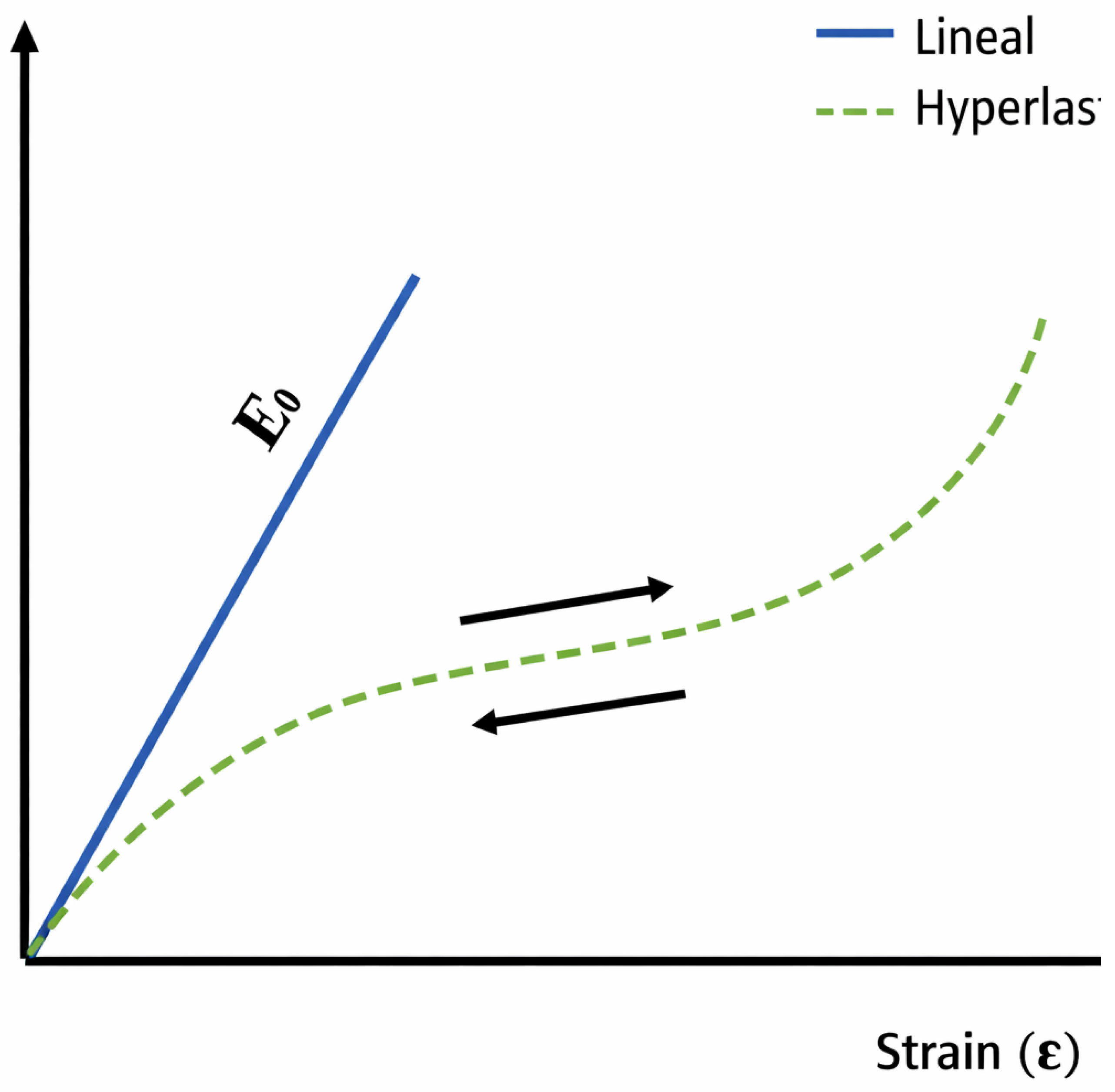
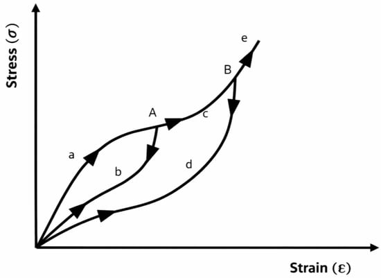
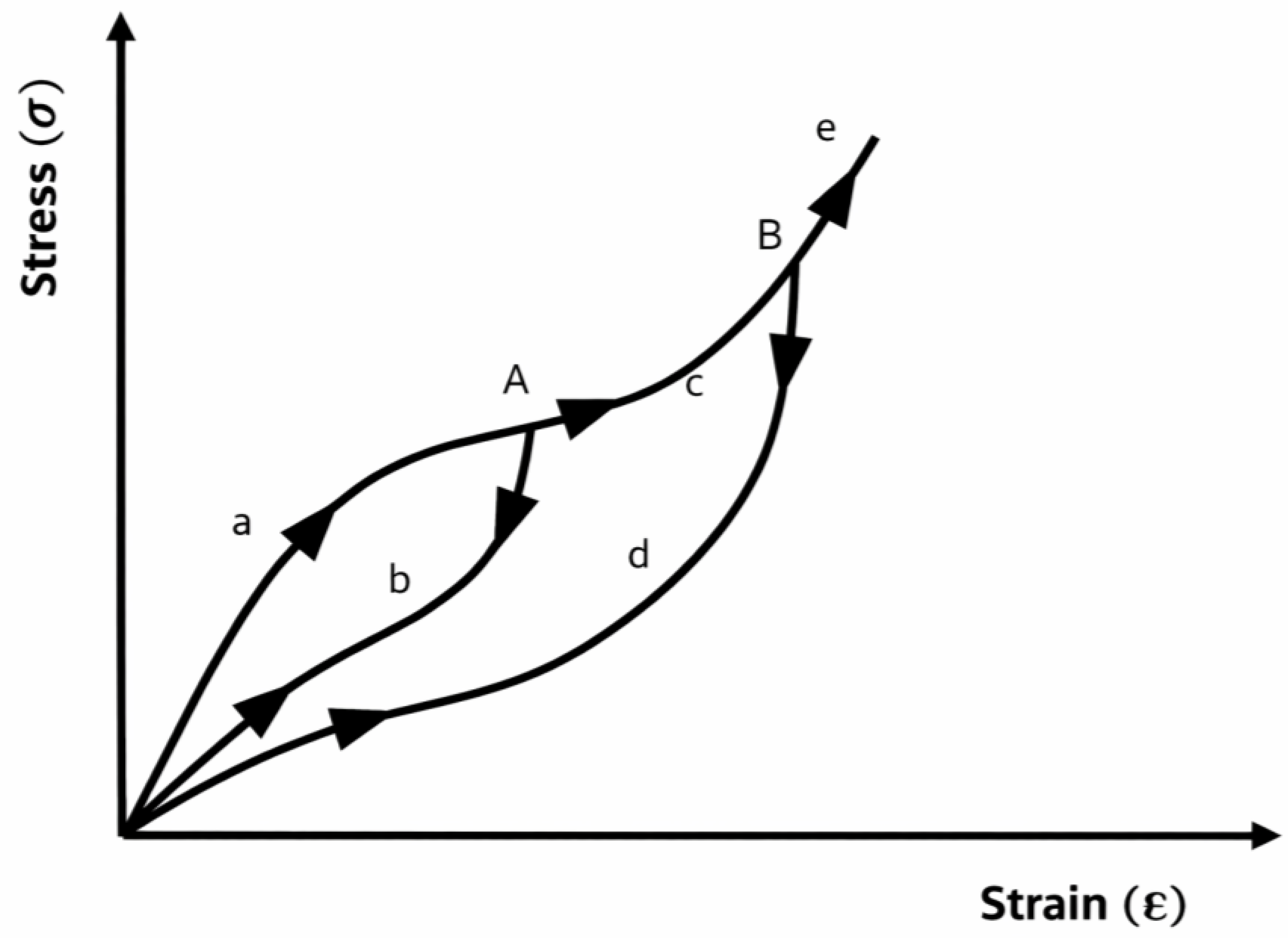
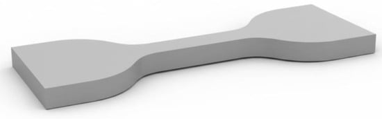
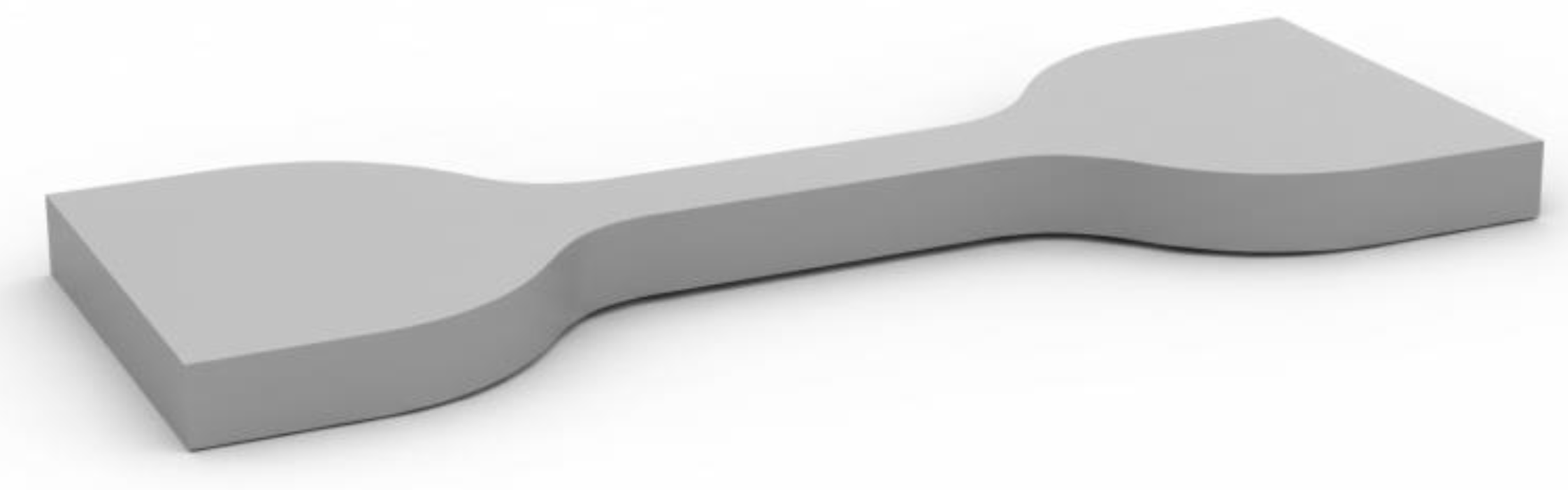
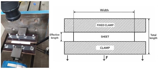
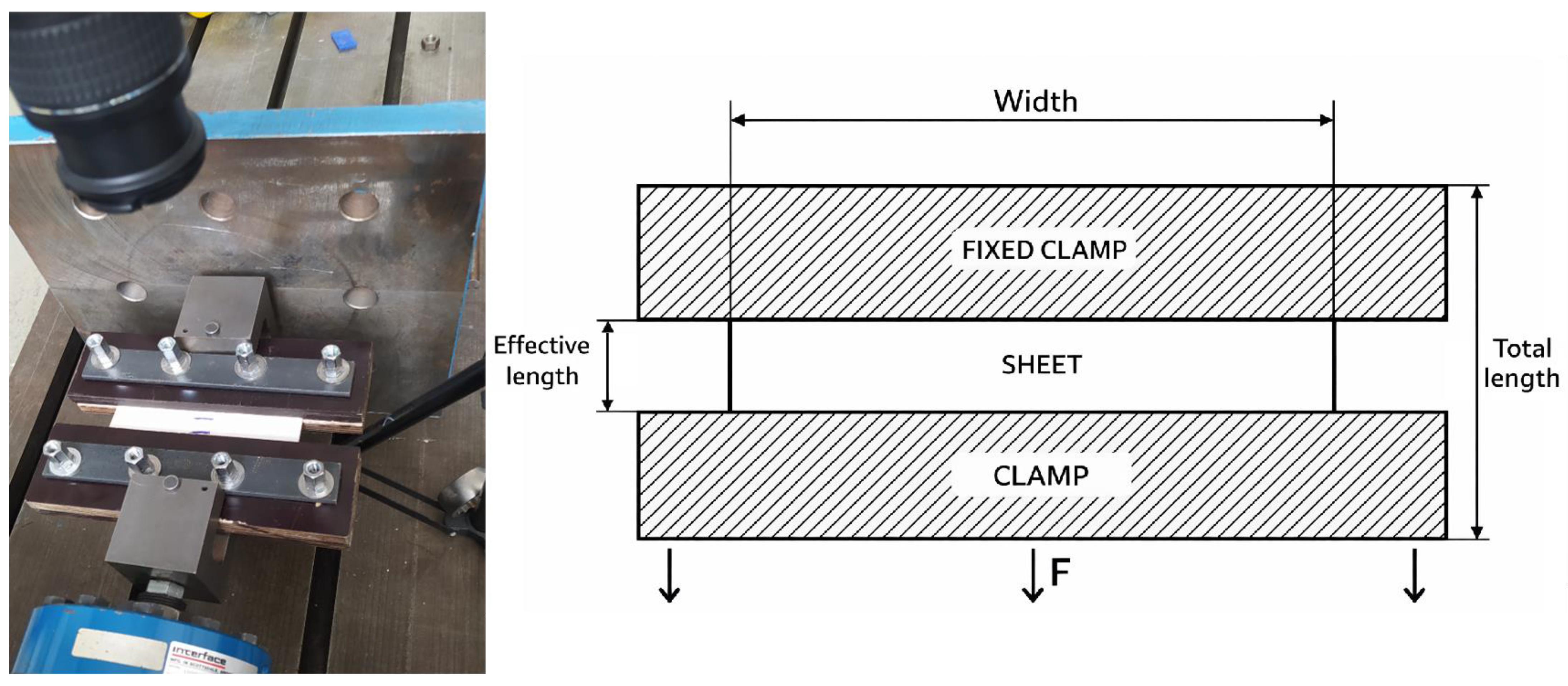
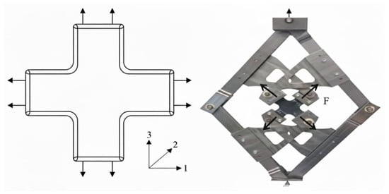
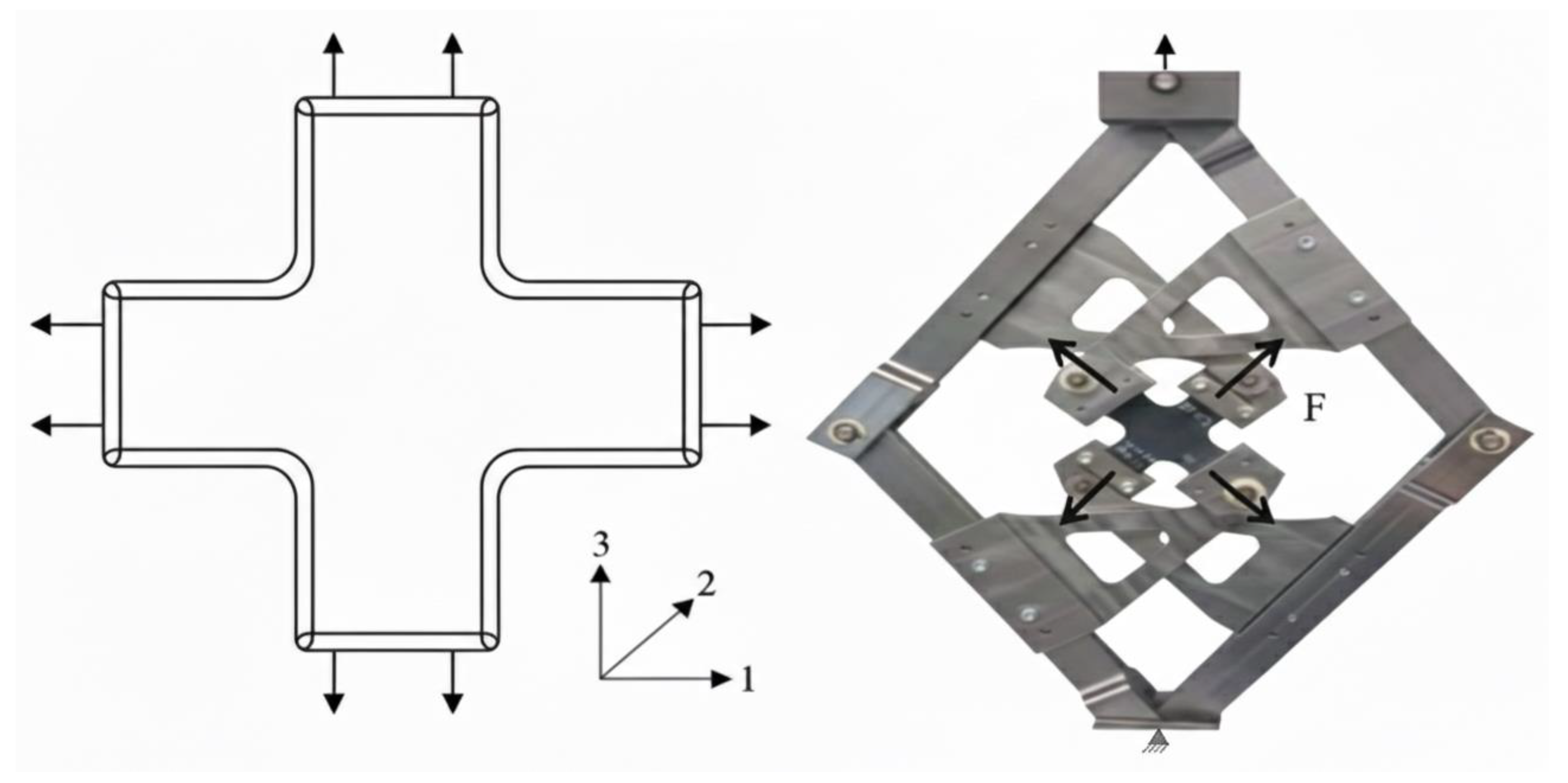
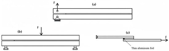
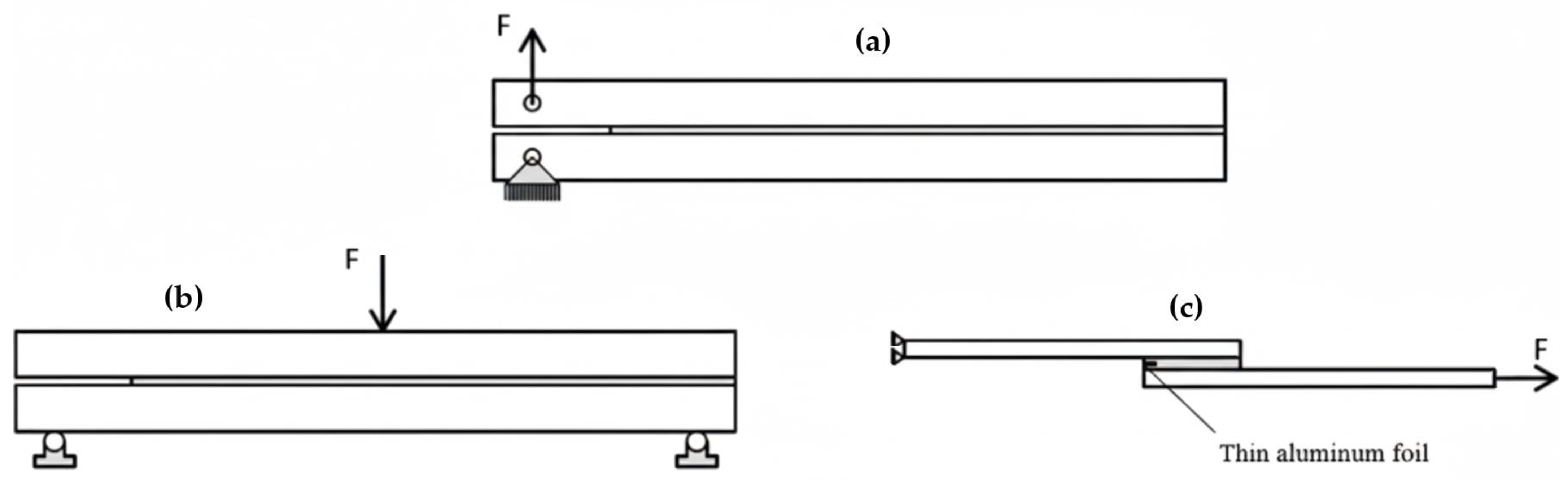
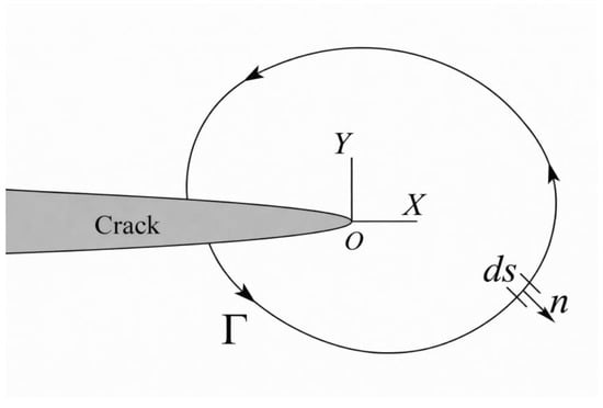
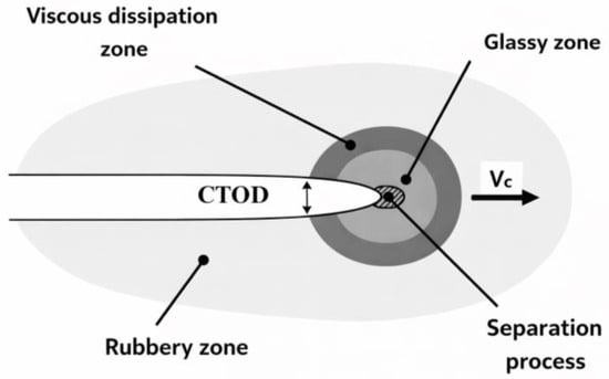
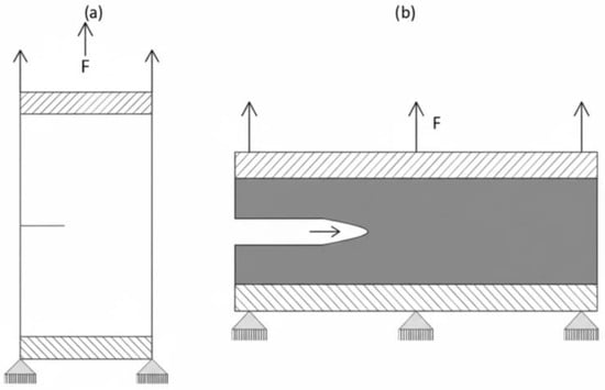
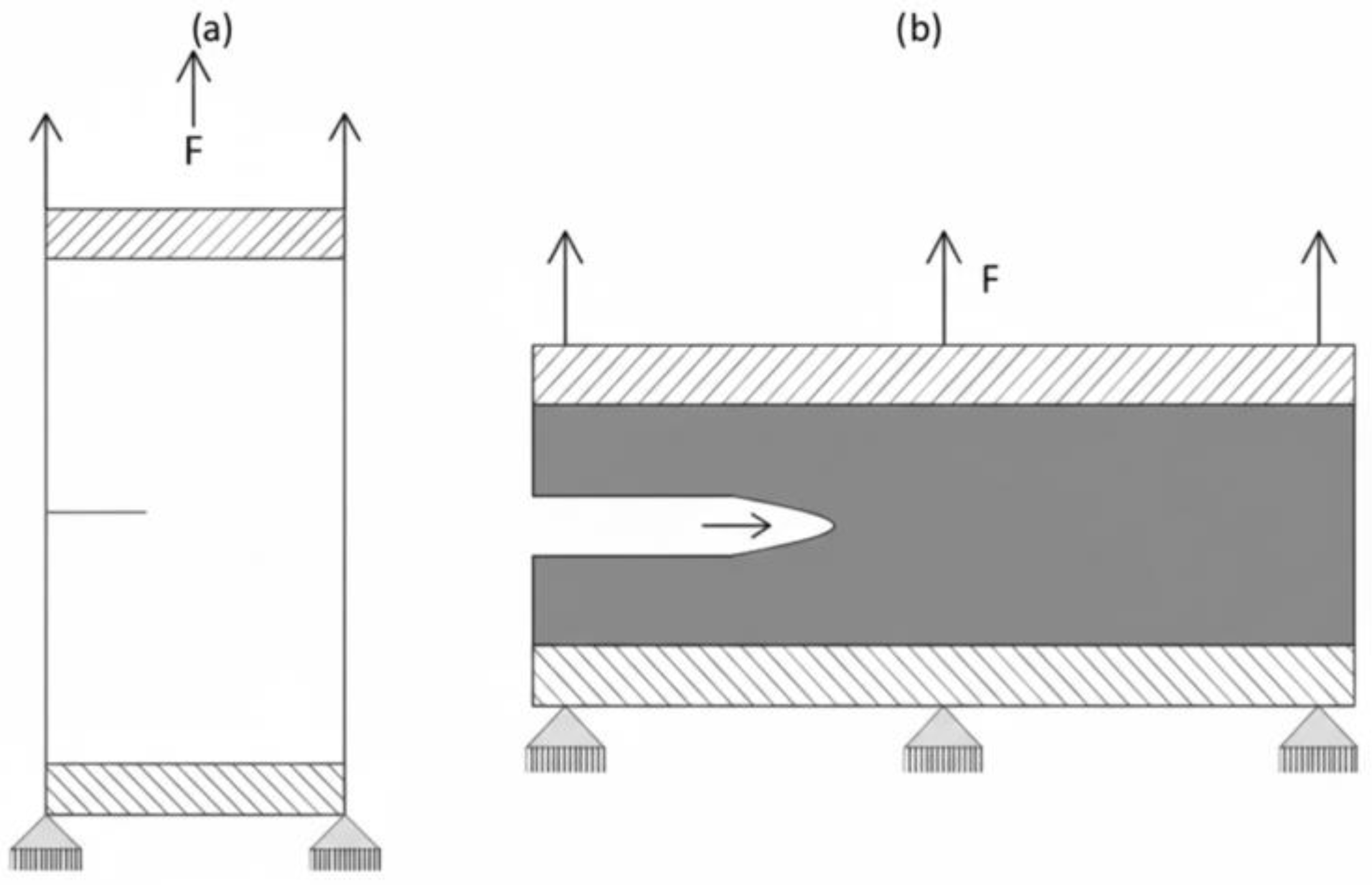
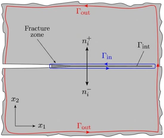
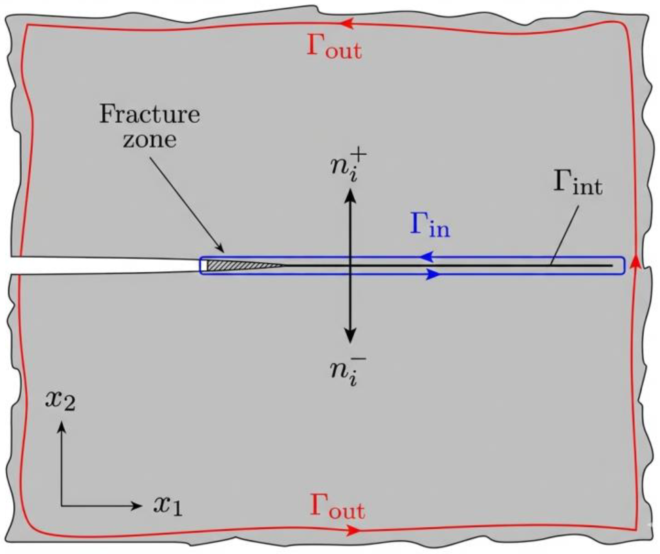
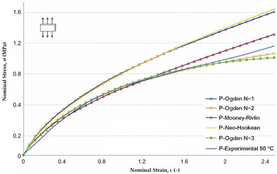
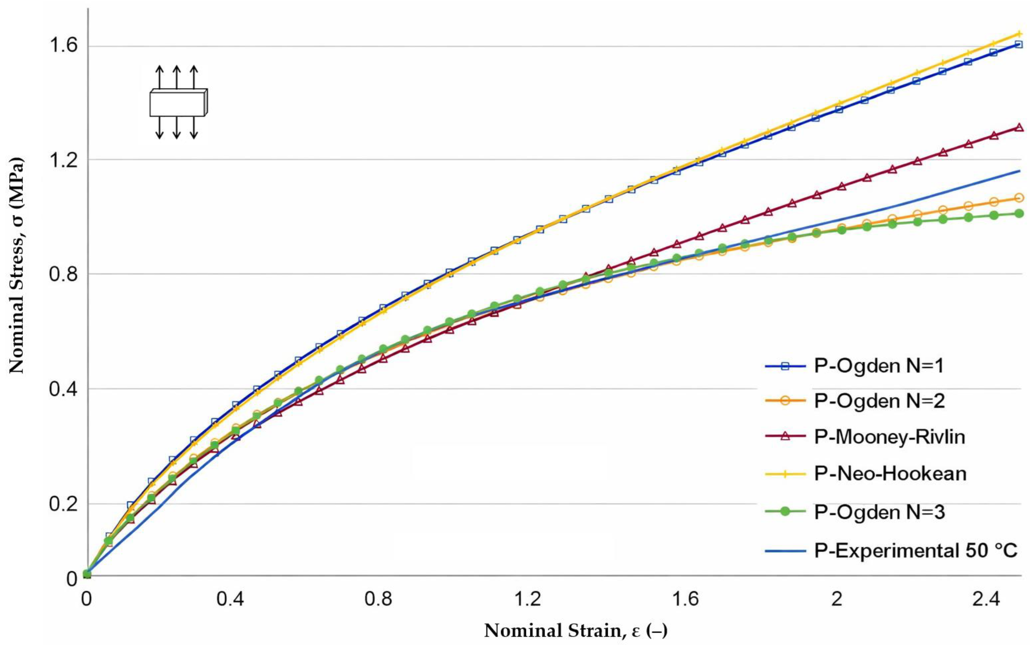

Disclaimer/Publisher’s Note: The statements, opinions and data contained in all publications are solely those of the individual author(s) and contributor(s) and not of MDPI and/or the editor(s). MDPI and/or the editor(s) disclaim responsibility for any injury to people or property resulting from any ideas, methods, instructions or products referred to in the content. |
© 2026 by the authors. Licensee MDPI, Basel, Switzerland. This article is an open access article distributed under the terms and conditions of the Creative Commons Attribution (CC BY) license.