


Abstract
We propose a topological data analysis framework for the study of damage evolution in anisotropic composite materials based on scalar filtrations defined on cubical complexes. Two complementary anisotropic filtrations are constructed from the structure tensor: a fibre-oriented filtration f1, capturing directional coherence, and a crack-oriented filtration f2, sensitive to isotropic and weakly oriented structures. Zero-dimensional persistent homology is analysed through merge trees built from the superlevel-set filtration via the transformation , providing a hierarchical representation of connected components. Higher-order connectivity is described using skeleton-based Reeb-like graphs. From these constructions, we derive spatial and global descriptors, including a topological danger map and a Topological Damage Complexity Index (TDCI) based on one-dimensional persistent homology. The behaviour of the TDCI is examined with respect to variations in its parameters and to image perturbations, showing consistent trends across the considered configurations. The results highlight complementary structural behaviours captured by the two filtrations and show a coherent correspondence with observed patterns. Overall, the proposed framework provides a mathematically grounded description of structural organisation. It is intended as an exploratory approach, and further work is needed to clarify its relationship with the underlying physical damage mechanisms.
Keywords:
TDA; anisotropic filtration; persistent homology; merge tree; Reeb graph; crack; composite 1. Introduction
For several decades, fibre-reinforced polymer matrix composites have proven their importance in many industrial fields such as aeronautics: their excellent properties allowing a considerable reduction in the structure mass. The structure may have aged in the environment in which it operates. This ageing can manifest itself in various ways, particularly through the combined action of temperature and humidity: this is known as hygrothermal ageing. The substrates and their surfaces are therefore no longer in their initial state.
The literature on the hygrothermal ageing of the polymer matrix of composite materials, particularly epoxy, shows that these materials exhibit complex behaviour. Moisture can cause physical changes (plasticisation, relaxation, hygroscopic swelling, migration of additives) or chemical changes (hydrolysis, oxidation) in the polymer. When these changes are pronounced, they cause leaching, cracking and swelling. Temperature accelerates the ageing process by increasing water diffusion and reducing saturation time [1,2,3,4,5,6]. With regard to composite materials, carbon fibres are not subject to hygrothermal ageing. However, their presence modifies the behaviour of the composite material compared to that of pure resin. The effects of the fibres are anisotropic diffusion along the fibres and at the fibre/matrix interface [7,8,9,10,11], increase in water concentration gradients [12,13,14], damage (blistering, cracking) related to osmotic differences between the two types of materials [12,15]. The consequences of this hygrothermal ageing are a decline in the mechanical properties of structures.
In addition to ageing, materials can be subject to mechanical damage such as scratches. Their surfaces are subjected to pressure and friction from hard particles or objects. A scratch test is defined as the sliding of an indenter, considered rigid, on a deformable surface, in this case the fibre-reinforced polymer matrix composite. The force applied can be constant or progressive at a given loading speed. The deformation applied depends on the indenter shape, the sliding speed, the loading force and the material nature. Tangential contact then changes the rheological behaviour of the scratch [16]. A purely elastic scratch is characterised by a circular contact shape and the absence of a groove. A viscoelastic scratch has asymmetrical grooves that recover over time [17,18]. Viscoelastic recovery is observed. In polymers, total or partial recovery of the grooves is observed. With a plastic scratch, a front ridge and two side ridges form. Plastic scratches may also be accompanied by other damage such as front or rear cracks and material removal such as chipping [19,20]. This damage inhibits the relaxation of the polymer after the indenter passes. On coated materials, blistering of the coating may also be observed. The coating behaviour is influenced by the substrate nature and their surface properties, even if the indenter does not penetrate beyond the adhesive film. For fibre-reinforced composite materials, the fibre presence in the bulk material does not necessarily improve scratch resistance. They increase brittle fractures and delamination. The scratch direction in relation to the fibre orientation has a significant impact on the penetration depth of the indenter. The more perpendicular the direction of the scratch to the orientation of the laminate first fibre, the more pronounced the damage. Fibre tearing and breakage under bending can be observed [21,22].
The experimental observations reported above highlight the progressive emergence of complex damage patterns during composite scratching, involving fibre bending, rupture, matrix displacement, and the formation of transverse cracks whose spatial extent increases with ageing time. While these mechanisms are well described locally through microscopy and scalar measurements such as groove depth or burr height, the resulting damage configurations exhibit an increasingly intricate spatial organisation. In particular, the coexistence and interaction of oriented fibres, cracks, and material accumulations give rise to heterogeneous structures whose evolution cannot be fully captured by purely metric descriptors. This motivates a complementary mathematical analysis focused on the global organisation of damage patterns and its evolution across ageing stages. In this work, we adopt a Topological Data Analysis framework to characterise these structures through merge trees, persistent homology, Reeb graphs, and skeleton-based representations, and to derive quantitative descriptors such as danger maps and a topological complexity index.
Topological Data Analysis (TDA) has emerged as a powerful mathematical framework [23,24,25,26,27] for characterising complex structures in materials science, particularly when classical geometric or statistical descriptors fail to capture global organisation and multi-scale phenomena. By encoding data through filtrations and studying the evolution of topological invariants such as connected components, loops, and higher-dimensional features, TDA enables a scale-independent analysis of material microstructures.
Persistent homology, in particular, has been successfully applied to the study of porous media [28], polycrystalline structures [29], fracture networks [30,31], and crack patterns in materials [32]. These approaches demonstrate that topological descriptors can effectively capture connectivity, defect distribution, and multi-scale organisation in complex microstructures. In addition, TDA has been combined with machine learning and image analysis techniques to improve defect detection and segmentation in composite materials [33].
Beyond persistence diagrams, tree- and graph-based constructions such as merge trees, Reeb graphs, and skeleton representations provide complementary insights into the hierarchical organisation of scalar fields [34,35,36]. These tools encode connectivity, branching, and structural evolution, and are particularly well suited for analysing damage patterns where interactions between features play a central role.
Recent developments have further highlighted the relevance of TDA in materials science. Persistent homology has been used to relate microstructural topology to physical properties, such as thermal conductivity in amorphous materials [37], and to extract interpretable descriptors from microscopy data [38,39]. More generally, recent studies and surveys emphasise the growing role of TDA in materials characterisation and industrial applications [40,41]. In the context of composite materials, Uy et al. [42] proposed a persistent homology-based framework combined with Wasserstein distances to distinguish crack initiation and propagation modes from high-resolution tomography data, illustrating the ability of topological descriptors to capture three-dimensional crack evolution. Similarly, Canot et al. [43] demonstrated that TDA can characterise roughness and defect organisation in bonded assemblies, highlighting its sensitivity to structural degradation. Together, these works support the use of topological descriptors as robust tools for analysing complex material structures.
However, most existing approaches rely on isotropic filtrations derived from grayscale intensity or distance-based functions. While effective for capturing global topological features such as connectivity and loop formation, these constructions do not explicitly encode the strong anisotropy inherent to fibre-reinforced composites, nor the directional nature of damage mechanisms such as fibre alignment, matrix displacement, and crack propagation.
In the context of scratched and aged composite materials, damage patterns often exhibit a marked directional organisation and a progressive restructuring driven by the interaction between fibres and cracks. These features may not be fully captured by standard isotropic descriptors, which can overlook certain orientation-dependent phenomena.
To address these aspects, we explore the use of anisotropic filtrations designed to reflect physically meaningful directions in the material. A fibre-oriented filtration is intended to capture the evolution of structural anisotropy associated with fibre organisation, while a crack-oriented filtration aims to highlight the emergence and connectivity of fracture networks. This dual-filtration framework provides a complementary topological perspective on damage evolution across ageing stages. This work is exploratory and methodological.
Our work investigates a topological framework for the analysis of ageing-induced damage in 3D woven composite materials. The approach builds on persistent homology-based methods while introducing several complementary extensions. First, we consider a dual anisotropic filtration aimed at distinguishing between fibre-aligned structures and transverse crack-related patterns, thereby providing a representation more consistent with the intrinsic anisotropy of composite materials. Second, in addition to persistence diagrams, we incorporate tree- and graph-based constructions, such as merge trees and Reeb-like graphs, in order to capture hierarchical organisation, connectivity, and branching structures within the observed patterns. These representations provide complementary spatial and structural information beyond standard topological summaries. Third, from these constructions, we derive a set of quantitative descriptors, including a topological danger map and a topological complexity index, which enable a comparative analysis across ageing stages and experimental conditions. Overall, the proposed framework aims to provide a coherent and structured description of the evolution of damage-related patterns while remaining primarily descriptive in its current form.
2. Topological Framework and Descriptors
This section introduces the topological framework used in the paper. We recall only the standard notions from topological data analysis (TDA) that are necessary for the presentation of the method, while emphasising the constructions specific to the present application. Detailed proofs and complementary formal developments are gathered in Appendix A.
2.1. Image-Based Topological Setting
Let denote the image domain associated with a microscopy or SEM acquisition of a scratched composite surface. After preprocessing, the image is represented by a scalar field
For , the sublevel sets
define a filtration of the image domain. In practice, all computations are performed after discretisation on a finite cubical complex K, and we denote by
the associated filtered cubical subcomplexes.
In this work, we focus on two homological dimensions:
- , describing connected components,
- , describing loop-like structures.
Persistent homology summarises the birth and death of these features along the filtration. To complement persistence diagrams, we also use merge-tree and skeleton-based representations in order to retain hierarchical and spatial information. These constructions are standard in TDA and are recalled here only in the form needed for the proposed pipeline.
2.2. Structure Tensor and Anisotropic Filtrations
To capture local directional information in damage patterns, we rely on the structure tensor. Let denote a grayscale image normalised to . Its spatial gradients are denoted by
The structure tensor at scale is defined by
where is a Gaussian kernel. Its eigenvalues are denoted by .
The ratio
provides a normalised measure of local isotropy. Based on this quantity, we define two complementary scalar fields:
By construction, is large in strongly anisotropic regions, whereas is large in weakly oriented or isotropic regions. In the present work, is intended to emphasise fibre-aligned patterns, while captures more isotropic or weakly oriented structures that may be compatible with crack-like configurations. This interpretation remains indirect and is based on consistency with the observed SEM patterns rather than on a direct physical segmentation.
For each , we consider the filtration
We also define the local energy
and restrict the analysis to reliable pixels by thresholding E at a quantile . The resulting scalar fields may then be smoothed to reduce spurious fluctuations.
Superlevel-Set Convention
For any filtration function f, we define
Merge tree constructions and -derived quantities are computed from g, so that high values of f correspond to early components in the associated superlevel organisation. In particular, since , one has
2.3. Persistent Homology, Merge Trees, and Skeleton-Based Graphs
For each filtration, persistent homology in dimension one is computed on the corresponding cubical complex. From the persistence diagram , we extract three global descriptors:
- the total persistence,
- the persistence entropy,
- the number of robust features above a threshold .
In dimension zero, we use merge trees associated with in order to describe the hierarchical organisation of connected components. Beyond their tree structure, merge trees induce a natural partition of the domain into regions associated with their branches; in what follows, this partition is referred to as the merge tree segmentation.
From thresholded supports of the filtrations, we also compute one-dimensional skeletons using homotopy-preserving thinning procedures. Endpoints, junctions, and total skeleton length are then extracted. These skeletons are used as discrete Reeb-like graphs, providing a compact representation of branching and connectivity.
2.4. Topological Danger Map
To obtain a spatially interpretable indicator, we introduce a topological danger map associated with a filtration f. This map combines three complementary contributions:
- the local filtration value ,
- a persistence-based contribution derived from the merge tree of ,
- a proximity term to the skeleton.
More precisely, the danger map is defined by
where is a persistence-weighted field induced by the merge-tree segmentation, and is a skeleton proximity term.
In the implementation used in this work, the coefficients are fixed to
This choice assigns the dominant contribution to the filtration value itself while incorporating a substantial but secondary topological correction through the persistence-based term. The skeleton proximity term is given a smaller weight so that it acts as a mild geometric regularisation without dominating the resulting map.
The additive structure of is motivated by the fact that the three terms represent normalised and complementary aspects of the underlying data: local intensity (through f), hierarchical topological persistence (through ), and geometric organisation (through ). Their convex combination provides a minimal and interpretable aggregation of these quantities. In practice, the resulting map is further normalised, quantile-clipped, and smoothed, which reinforces its stability and removes spurious local fluctuations.
The purpose of this map is not to provide a predictive damage law. It should rather be interpreted as an exploratory and descriptive indicator highlighting regions where high filtration values, strong topological persistence, and coherent geometric organisation coincide. An assessment of its predictive ability would require time-resolved data and is beyond the scope of the present work.
2.5. Topological Damage Complexity Index
To summarise the global complexity of the damage patterns, we introduce the Topological Damage Complexity Index (TDCI), computed from the one-dimensional persistence diagram of a filtration.
The TDCI combines three quantities derived from : the total persistence, the persistence entropy, and the number of robust cycles above a threshold . After normalisation across ageing states, these quantities are aggregated into a scalar descriptor taking values in .
The TDCI is used in this work as an exploratory global summary of the topological complexity highlighted by a given filtration. It is computed independently for and in order to compare their evolution across ageing stages.
2.6. Standard Background and Stability
Most of the notions used above (cubical complexes, persistence diagrams, merge trees, and their basic stability properties) belong to the standard background of TDA. In the present work, the main contributions lie in:
- the definition of two anisotropic filtrations adapted to composite damage patterns,
- the joint use of persistence, merge-tree, and skeleton-based descriptors,
- the introduction of the topological danger map and the TDCI as interpretable summaries.
For convenience, we record the following standard stability statements.
Proposition 1 (Stability of persistence diagrams).
Let be two tame functions on a finite cubical complex K. Then, for any homological dimension ,
where denotes the bottleneck distance.
Proposition 2 (Stability under the superlevel-set convention).
Let and define and . Then
Thus, any stability estimate stated for g immediately transfers to f.
Proposition 3 (Stability of the TDCI components).
Under small perturbations of the persistence diagram , the total persistence and persistence entropy vary continuously, while the threshold count is locally constant away from the threshold boundary. Consequently, the TDCI is stable under small perturbations whenever the relevant persistence values do not cross the threshold τ.
Detailed proofs and complementary formal developments are given in Appendix A.
3. Materials and Data Description
3.1. Composite Material and Ageing States
The polymer matrix composite material studied is a 3D woven fabric. An aeronautical epoxy/amine including inorganic particles is used as matrix. Carbon fibres are used as reinforcement. The epoxy resin formulation and the 3D woven fabric architecture are confidential. The samples have the following dimensions: . Hygrothermal ageing is carried out on the samples in immersion in distilled water at 70 °C in a Climats VRT Extreme 320 climatic chamber (CLIMATS, Martilac, France) during 200, 300 or 650 days. Before hygrothermal ageing, the samples are stocked in an air-conditioned room ( °C, RH). The hygrothermal ageing of this composite material has already been the subject of previous studies [44,45]. Water absorption caused morphological and chemical changes. Cracks, matrix leaching and particle migration within the material were observed using scanning electron microscopy (SEM). These are caused by various damage phenomena such as hydrolysis and oxidation, characterised by macromolecular chain scission, which are observed by Fourier transform infrared spectroscopy (FTIR), energy dispersive X-ray spectroscopy (EDS) and X-ray photoelectron spectroscopy (XPS). This composite material degradation increases with ageing time. Thus, a gradual increase in mass due to water absorption is measured on the samples. This is counterbalanced by a gradual loss of mass, measured by desorption, linked to the matrix degradation. On the surface, hygrothermal ageing causes a slight decrease in average roughness Ra. An increase in peak height and a decrease in valley depth are measured. This may be due to the migration and deposition of particles on the peaks and valleys.
3.2. Micro-Scratch Test
In order to evaluate the fibre/matrix adhesion of the composite material, a progressive load micro-scratch test was performed using Anton Paar’s SCID-3000 scratch test bench, (Anton Paar, son siège est situé à Graz, Austria). During the test, several parameters are recorded in real time, including the coefficient of friction, acoustic emission, penetration depth, and applied force. Figure 1 shows a schematic representation of the test.
Figure 1.
Scheme of the micro-scratch test.
Six scratches are performed on each sample. The scratches are systematically carried out along fibre strands covered with resin, in the longitudinal direction, in order to minimise variability induced by fibre undulation and differences between fibre-rich and resin-rich areas.
- Normal force (or load): from 0.03 to 30 N;
- Speed: 50 mm/min;
- Scratch length: 10 mm;
- Indenter: C 215 Rockwell conical tip, diameter 200 μm and angle .
Microscopic observations (optical and SEM) are performed along the scratch tracks, from the initiation zone to the head of the scratch, allowing the identification of deformation and damage mechanisms such as fibre displacement, matrix cracking, and material removal. The images used in the present study correspond to selected regions of interest extracted from these observations. The selection is based on representativeness of the observed structural patterns, sufficient image quality, and absence of acquisition artefacts. The number of analysed images per ageing condition remains limited, and no formal statistical sampling strategy was applied. The results should therefore be interpreted as a structural analysis of representative configurations rather than as averaged measurements over large datasets.
3.3. Image Acquisition and Preprocessing
Images are acquired using scanning electron microscopy (SEM). The ZEISS EVO HD1 environmental SEM (ZEISS, Oberkochen, Germany) is used. In order to perform chemical analyses in parallel, it is coupled with the AZtec energy dispersive X-ray spectrometer (EDS) from Oxford Instruments (Oxford Instruments, Abingdon-on-Thames, UK). The samples must withstand intense electron bombardment, which makes this technique unsuitable for polymers. To perform the analyses, the SEM is operated in a degraded vacuum, with a pressure of 20 Pa. The bombardment voltage is between 10 and 15 kV. The preprocessing pipeline is applied consistently to all selected regions of interest.
4. Methods
4.1. Software Environment and Libraries
The present study focuses on the topological analysis of representative microstructural configurations extracted from controlled micro-scratch experiments. Persistent homology, merge trees, and cubical complex filtrations are computed using the GUDHI version: 3.11.0 library, which provides native support for cubical complexes and image-based filtrations.
The choice of GUDHI is motivated by its ability to handle grayscale images directly as cubical complexes, to compute persistence diagrams in dimensions 0 and 1, and to extract merge-tree-like structures associated with sublevel-set filtrations. These features are essential for the analysis of damage patterns represented as scalar fields on image grids.
Standard scientific Python version: 3.11.11 libraries (NumPy, SciPy) are used for numerical operations, while image preprocessing and structure tensor computations rely on scikit-image. Graph-based constructions and skeleton representations are implemented using networkx and morphological operators.
4.2. Preprocessing and Scalar Field Construction
All images are first converted to grayscale and normalised to the range . A contrast enhancement step is applied using adaptive histogram equalisation to improve the visibility of damage patterns.
The anisotropy field is computed from the structure tensor at multiple spatial scales. Specifically, Gaussian smoothing is applied with scales , and the structure tensor is further regularised using a secondary smoothing parameter .
At each scale, the eigenvalues of the structure tensor are computed, and the anisotropy measure is defined as
with . The final scalar field is obtained by taking the maximum response across scales.
A reliability mask is then defined using the local energy , thresholded at the quantile , in order to suppress low-information regions. The resulting scalar field is smoothed using a Gaussian filter with standard deviation .
All preprocessing parameters are kept fixed across all experiments.
Skeleton Extraction
The skeleton used in the present work is obtained from a binarised support of the filtration f, designed to capture highly anisotropic structures.
First, a fracture-like mask is defined by thresholding the filtration at a high quantile level (typically ), followed by a reliability masking based on the local energy. Small connected components are removed using a minimum size criterion, and a morphological closing with a disk structuring element is applied to ensure spatial coherence.
The skeleton is then computed using a homotopy-preserving thinning procedure, implemented via the standard skeletonize operator from scikit-image. This method produces a one-pixel-wide representation of the binary support while preserving its topological structure (in particular its connectivity and cycles).
From this skeleton, a graph representation is extracted by identifying:
- endpoints (pixels with degree 1),
- junctions (pixels with degree ),
based on the local connectivity in a neighbourhood. A spatial thinning procedure is applied to these nodes to avoid clustering effects, using a minimum distance criterion.
The resulting structure is interpreted as a discrete Reeb-like graph, providing a compact representation of branching and connectivity patterns in the underlying structures.
4.3. Method Overview
The proposed methodology follows a unified topological pipeline applied independently to the two anisotropic filtrations and . The successive steps are as follows:
- Anisotropic feature extraction. The structure tensor is computed on the image domain to extract local directional information. From its eigenvalues, two complementary anisotropic filtration functions are defined: , intended to emphasise fibre-aligned and strongly anisotropic structures, and , designed to highlight more isotropic or weakly oriented patterns, which may be associated with crack-like features and matrix alterations.
- Cubical filtration construction. Each filtration is represented on a finite cubical complex induced by the image grid. Sublevel-set filtrations are constructed and form the basis for all subsequent topological computations.
- Persistent homology. Persistent homology is computed independently for and . Zero-dimensional persistence captures the evolution and merging of connected components, while one-dimensional persistence quantifies loop-like structures induced by damage patterns.
- Merge tree computation. For each filtration , a merge tree is constructed using the same algorithmic procedure, namely a component tree implemented via a union-find data structure with elder rule. This yields a hierarchical representation of the connectivity structure associated with each filtration.
- Topological segmentation and skeletonisation. The merge trees induce a segmentation of the domain into persistence-weighted regions. From dominant regions, skeletons are extracted to capture the main damage propagation pathways, and Reeb-like graphs are derived from these skeletons.
- Topological indicators. Spatial danger maps are constructed by combining local filtration values, persistence-based weights, and skeleton proximity. In parallel, a Topological Damage Complexity Index (TDCI) is computed from one-dimensional persistence diagrams to provide a global summary of damage complexity.
This pipeline is applied identically to and , allowing a direct comparison between fibre-related and crack-related damage mechanisms across ageing stages.
5. Results
5.1. Visual and Topological Results
Scratches that start from the right to the left on the micrograph on composite substrates are observed by optical microscope in Figure 2 and the traces of the scratches intensify with increasing load. On pristine samples, the pile-up formation is visible on the last four millimetres of the scratch. Scratch magnifications issued from scanning electronic microscopy enable to identify the fibre presence in the pile-ups; Figure 3. During its passage, the indenter has forced the fibres to bend and move. The broken fibres are carried away with the matrix pile-ups. These material displacements on either side of the indenter apply tension to the material, which cracks perpendicular to the scratch direction over the last two millimetres, as can be seen in the SEM images for all ageing times [21]. After 200 days of hygrothermal ageing (Figure 3b), the fibre displacement is greater and the cracks appear more rapidly, over the last four millimetres. Material pull-outs in the groove are noticeable.
Figure 2.
Optical microscopies of scratches on composite substrate surfaces according to ageing time.
Figure 3.
SEM images of the scratch heads on composite substrates: (a) pristine, (b) 200-day aged, (c) 300-day aged, (d) 650-day aged.
The phenomena intensify over ageing time. After 300 days of ageing (Figure 3c), the frontal cracks become more pronounced and coalesce at the center of the groove. They appear after five millimetres of scratching. The fibre rupture and displacement in the pile-ups is significant. After 650 days (Figure 3d), the amount of displaced fibres is even greater. The groove can no longer be distinguished because of the broken and displaced fibres.
These visual observations provide the experimental context for the topological analysis developed below, where the two filtrations and are used to characterise complementary aspects of the evolving damage patterns.
5.2. Fibre-Oriented Anisotropic Filtration
The anisotropic filtration is designed to emphasise fibre-aligned structures exhibiting a dominant orientation. The results combine a hierarchical analysis based on the merge tree constructed from , a geometric description using skeletons and Reeb-like nodes, and a topological danger map integrating local anisotropy, persistence, and geometric coherence.
Interpretation of p and A in the Merge-Tree Analysis
In the merge-tree representation of , each branch is associated with two complementary quantities. The persistence measures the stability of a connected component across filtration thresholds, while A quantifies the spatial extent of the corresponding region. In this study, p and A are used as descriptive indicators of topological robustness and geometric size, respectively. Their interpretation in terms of material structure remains indirect and should be understood as a proxy rather than a direct measurement.
Across the investigated ageing stages (pristine, 200 days, 300 days, 650 days), the merge-tree analysis reveals the presence of persistent branches already in the pristine material. This indicates that the filtration detects structured components with a certain degree of stability in the initial configuration.
With ageing, a tendency toward simplification of the merge-tree structure can be observed, with a reduced number of dominant branches in some cases. This evolution suggests a redistribution of the detected structures across filtration levels. However, no direct conclusion can be drawn regarding the underlying physical mechanisms without additional independent measurements.
At later stages (300 and 650 days), the observed patterns remain comparable, although descriptors such as persistence and spatial extent continue to evolve. These changes reflect modifications in the organisation of the structures captured by while preserving a certain level of global coherence in the topological descriptors.
The associated skeletons and Reeb-like graphs highlight elongated structures with moderate connectivity. These geometric features are consistent with the type of patterns emphasised by ; The topological danger map identifies regions with higher combined values of anisotropy, persistence, and geometric coherence. These regions can be interpreted as areas of increased topological activity.
For completeness, the full set of topological and geometric representations for all ageing stages (pristine, 200 days, and 650 days) is provided in Appendix B. These figures confirm the progressive evolution described above and support the robustness of the observed fibre-oriented structures across time.
5.3. Crack-Oriented Anisotropic Filtration
The anisotropic filtration captures isotropic or weakly oriented structures and may therefore be sensitive to patterns associated with structural heterogeneity, including features that can be related to crack-like configurations.
The analysis combines several complementary representations: a hierarchical description based on the merge tree constructed from , a geometric characterisation using skeletons and Reeb-like nodes, one-dimensional persistent homology, and the associated topological danger maps . These elements provide different perspectives on the organisation of the structures identified by the filtration.
In the pristine state, the merge tree exhibits several persistent branches associated with spatially extended components. These structures may reflect initial heterogeneities or features introduced during the experimental preparation. However, their precise physical origin cannot be established solely from topological data.
At 200 days, the distribution of persistence values and the geometry of the associated regions evolve, suggesting a reorganisation of the detected structures. This stage may correspond to a transitional regime.
At 300 days, the merge tree displays a broader distribution of persistence values and a larger number of branches. This increase in topological complexity is accompanied by a more structured skeleton and a higher number of branching nodes in the Reeb-like graph. These observations indicate a diversification of the structures detected by , without implying a direct characterisation of physical crack networks.
At 650 days, the merge tree remains composed of multiple persistent components, often associated with larger spatial regions. The skeleton exhibits increased branching, and the danger map highlights more extended connected areas. These features are consistent with a redistribution of the topological descriptors toward larger-scale structures, although no direct physical validation is available at this stage.
Overall, captures an evolution of the spatial organisation of the detected structures, with an increase in topological complexity followed by a redistribution at larger scales. In contrast to , which emphasises directional anisotropy, is more sensitive to spatially distributed and weakly oriented features. This distinction is consistent at the level of the descriptors, but its physical interpretation should remain cautious.
The topological danger map exhibits regions of higher topological activity based on combined criteria. These regions may correspond to structurally significant areas; however, this interpretation remains tentative and requires confirmation through complementary experimental observations.
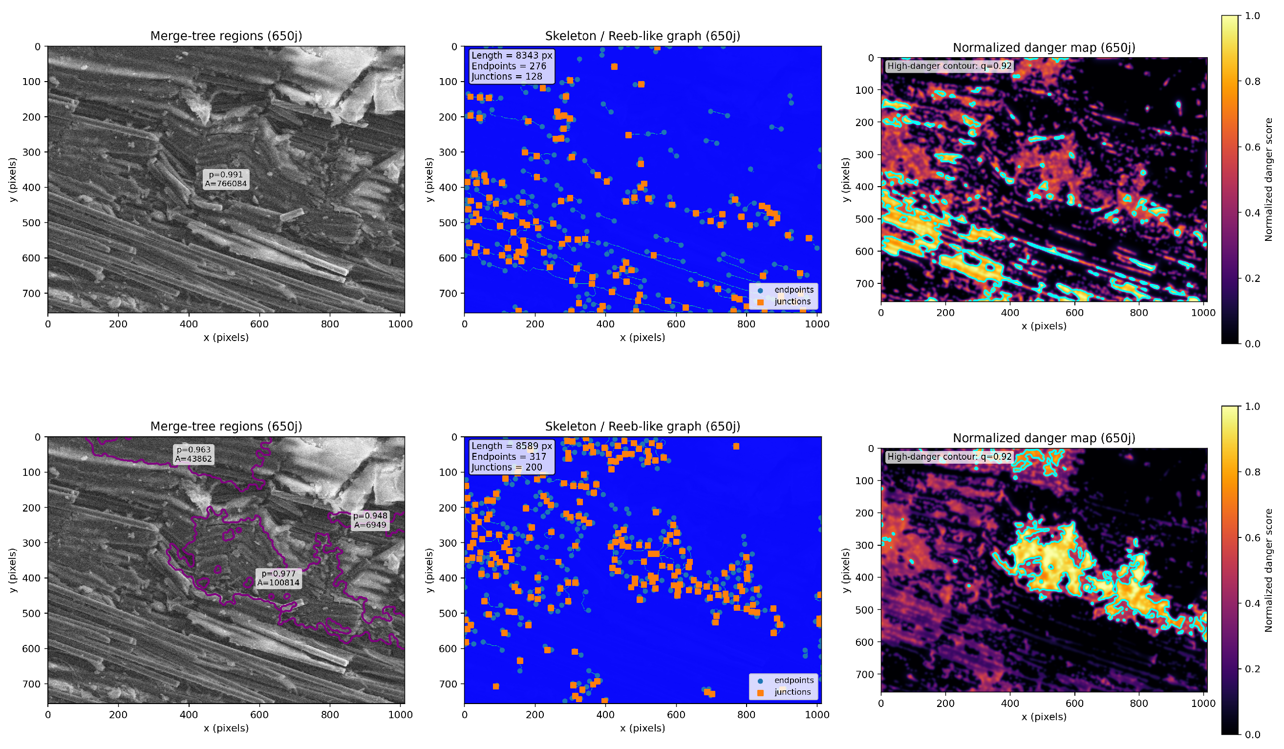
The complete set of results for all ageing stages (pristine, 200 days, and 650 days) is provided in Appendix B. These images provide a consistent visual support for the trends observed at 300 days (Figure 4).
Figure 4.
Topological structural representations at 300 days for the two filtrations. Top: fibre-oriented filtration . Bottom: crack-oriented filtration . Each row shows (from left to right): dominant merge-tree regions (filtered by persistence and area), the associated skeleton (Reeb-like graph) with quantitative descriptors (total length, number of endpoints, and junctions), and the normalised danger map with high-risk contour (quantile ). The filtration is designed to emphasise elongated fibre-aligned structures with moderate connectivity, while reveals a denser and more interconnected crack network, reflected by an increased number of junctions and localized high-risk regions.
The present results should be interpreted as exploratory, rather than as a definitive characterisation of the underlying physical processes.
5.4. Comparison of Descriptors
To provide a synthetic view of the structural organisation captured by the two filtrations, we report in Table 1 a set of topological and geometric descriptors computed across ageing stages. These include quantities derived from one-dimensional persistent homology, as well as geometric characteristics of the associated skeletons and merge-tree regions. This comparison aims to highlight the differences in the evolution of the structures detected by and , and to support the observations discussed in the previous sections.
Table 1.
Summary of topological and geometric descriptors for the two filtrations (fibre-oriented) and (crack-oriented) across ageing stages. The table reports -based descriptors, including the number of robust one-dimensional topological features ( count) and the sum of their persistence values ( persistence), together with geometric characteristics of the associated skeletons (total length and number of junctions) and the number of persistent regions extracted from the merge tree. These descriptors provide complementary information on the evolution of structural complexity, connectivity, and spatial organisation under the two filtrations.
A first observation concerns the -based descriptors. For both filtrations, the number of one-dimensional topological features ( count) tends to decrease from the pristine state to later ageing stages, although this evolution is not strictly monotonic. This trend suggests a reduction in the number of detected cycles, which may reflect a simplification or a redistribution of the underlying structures captured by the filtrations.
The total persistence exhibits a similar overall decrease, with values at later stages generally lower than in the pristine configuration. This indicates that the detected topological features tend to be less persistent across filtration levels. From a descriptive perspective, this may correspond to a reduced stability of the associated structures, although no direct physical interpretation can be inferred without complementary measurements.
The geometric descriptors derived from the skeletons show a consistent reduction in total length for both filtrations between the pristine state and intermediate ageing stages. At later stages, slight increases are observed in some cases, indicating that the evolution is not strictly monotonic. These variations suggest a reorganisation of the geometric support of the structures, rather than a simple degradation or growth process.
The number of junctions exhibits a marked difference between the two filtrations. While shows a gradual decrease in the number of junctions, maintains higher values throughout all ageing stages. This indicates that the structures detected by remain more connected or branched at the level of the skeleton representation. This difference is consistent with the distinct sensitivity of the two filtrations, although it should not be interpreted as a direct measure of physical connectivity.
The number of persistent regions extracted from the merge tree remains stable for (equal to three across all stages), whereas it decreases for after the pristine state. This suggests that the large-scale organisation detected by is preserved in terms of the number of dominant components, while tends to concentrate the structure into fewer regions. Again, this observation is purely descriptive and does not imply a direct interpretation in terms of material processes.
Overall, the descriptors indicate distinct evolutionary behaviours for and . The filtration is associated with a progressive reduction in connectivity and structural diversity at the level of the descriptors, whereas maintains higher levels of branching and a more stable number of dominant regions.
The descriptors reported in Table 1 are derived from filtration-dependent constructions and from two-dimensional data. As a consequence, they provide indirect information on the underlying structures. The observed trends should therefore be interpreted as indicative of changes in the topological and geometric organisation, rather than as direct measurements of physical properties.
5.5. Comparison with Conventional Crack Detection Methods
To further assess the relevance of the proposed topological descriptors, we compare the -based representation with a classical edge detection method, namely the Canny operator. This comparison aims to highlight the differences between gradient-based approaches and topological descriptors in capturing the structural organisation of the material.
Figure 5 presents a comparison between the SEM image, the Canny edge map, and the -based topological danger map for the pristine sample. The SEM image reveals a well-defined fibrous structure with transverse cracks located in the central region, oriented approximately perpendicular to the main fibre direction. Canny edge detection predominantly captures high-gradient structures aligned with the fibres, producing elongated contours that follow the dominant anisotropic texture. Although some transverse features are detected, they remain fragmented and lack spatial coherence, making the crack network difficult to identify. In contrast, the -based danger map exhibits connected regions located in the same areas as the transverse crack patterns observed in the SEM image. These regions exhibit higher intensity and form coherent structures, reflecting a loss of directional organisation and an increase in local structural complexity. These observations suggest that the proposed topological descriptors capture structural information that is not fully represented by classical gradient-based image processing methods.
Figure 5.
Comparison between the annotated SEM image, Canny edge detection, and the topological danger map for the pristine sample. The SEM image suggests the presence of fibre breakage and transverse crack-like features in the central region. Canny edge detection primarily captures high-gradient structures aligned with the fibres and only partially detects transverse patterns, which tend to appear fragmented and spatially discontinuous. In comparison, the -based danger map highlights regions exhibiting a higher level of spatial coherence, some of which overlap with the annotated areas. These regions may be associated with zones of reduced directional organisation and increased structural complexity. This comparison suggests that, while classical methods rely on local intensity gradients, the proposed topological framework captures additional structural information related to connectivity and multi-scale organisation. However, this correspondence should be interpreted with caution and does not constitute a direct identification of crack structures.
The filtration does not explicitly detect cracks, but rather exhibits regions of reduced anisotropy and structural disruption, which are consistent with crack-like patterns observed in SEM images.
Preliminary Validation Against Manually Annotated Crack Structures
A preliminary validation against manually annotated crack structures was performed. Manual annotation of crack-like features was carried out on the pristine sample, for which cracks are clearly visible in the SEM images. The annotation was produced as a binary mask , where pixels belonging to cracks are assigned value 1 and the background 0.
To enable comparison with the proposed method, the -based danger map was converted into a binary mask by thresholding:
where is chosen as a high quantile (e.g., 90th percentile) of the distribution in order to isolate the most critical regions.
The spatial agreement between and was quantified using standard overlap metrics. The Intersection over Union (IoU) and Dice coefficient are defined as
These quantities were computed using pixel-wise logical operations implemented with standard image processing tools (NumPy 1.26.4/scikit-image 0.25.2).
The comparison reveals a non-trivial spatial correspondence (IoU , Dice ), indicating that the proposed topological descriptor captures structures compatible with visually identified cracks.
However, for more advanced ageing stages (e.g., 300 days), the binary overlap between manual annotations and the danger map becomes significantly less meaningful. This is likely due to the increased structural complexity, the more diffuse nature of damage, and the inherent subjectivity of manual annotation. We note that these metrics provide only a coarse validation, as they depend on the threshold and on the inherent variability of manual annotations.
These observations indicate that the filtration should not be interpreted as a direct crack segmentation method, but rather as a descriptor capturing a broader topological organisation correlated with crack-related phenomena.
5.6. TDCI-Based Comparison of Filtrations and
To complement the spatial and structural analyses presented above, we consider a global descriptor derived from one-dimensional persistent homology, namely the Topological Damage Complexity Index (TDCI). This index provides a synthetic measure of the distribution and persistence of loop-like features across ageing stages.
The comparison of the TDCI computed from the filtrations and aims to illustrate potential differences in the evolution of the structures captured by the two representations while remaining within a descriptive framework. For the fibre-oriented filtration , the TDCI exhibits an overall decreasing trend from the pristine state to 650 days. This evolution suggests a progressive modification of the fibre-aligned anisotropic patterns captured by the filtration. From a descriptive perspective, this trend is consistent with a reduction in the diversity and persistence of the corresponding topological features.
In contrast, the crack-oriented filtration shows a non-monotonic evolution of the TDCI. The relatively high value observed in the pristine state may be associated with structures introduced during the scratching process, such as transverse features already present before ageing. At 200 days, the TDCI indicates a modification of these initial structures, suggesting a possible transitional regime in the organisation of the detected patterns.
At 300 days, the increase in TDCI is consistent with a higher level of topological complexity, which may correspond to a diversification of the structures captured by the filtration, including the emergence of interacting features. At 650 days, the subsequent decrease in TDCI suggests a redistribution toward larger-scale structures, leading to a reduced diversity of topological features at the global level.
Overall, these observations indicate that and capture different aspects of the structural organisation under ageing. The filtration is more sensitive to directional anisotropic patterns, while exhibits more spatially distributed and weakly oriented structures. This distinction is observed consistently at the level of the descriptors, although its interpretation in terms of physical mechanisms remains indirect. The evolution of the Topological Damage Complexity Index for the two filtrations is shown in Figure 6.
Figure 6.
Evolution of the Topological Damage Complexity Index (TDCI) across ageing stages for the filtrations and . The two curves exhibit distinct behaviours, reflecting the complementary roles of anisotropic fibre organisation and crack-related isotropic structures during ageing.
5.7. Sensitivity Analysis of the TDCI with Respect to Weighting and Robustness Threshold
To further assess the reliability of the proposed descriptor, we first analyse its sensitivity with respect to its internal parameters, namely the weighting coefficients and the robustness threshold.
5.7.1. Sensitivity to Weighting Coefficients
The TDCI combines three normalised quantities derived from one-dimensional persistent homology: the total persistence , which reflects the overall lifetime of topological features; the persistence entropy H, which measures the diversity of persistence values; and the number of robust features , corresponding to the number of persistence pairs whose lifetime exceeds a given threshold .
The TDCI is defined as a weighted combination of these three components. To evaluate the influence of the weighting scheme, several configurations were considered. In addition to a uniform weighting , three configurations were introduced to emphasise each component individually:
- Persistence-dominated (sigma): , emphasising the total persistence ;
- Entropy-dominated: , emphasising the diversity of persistence values;
- Robust-features-dominated (nrobust): , emphasising the number of features with lifetime above the threshold .
The resulting evolutions are shown in Figure 7. For the fibre-oriented filtration , all weighting configurations lead to a consistent monotonic decrease in the TDCI from the pristine state to 650 days. Although the amplitude of the index varies depending on the relative importance assigned to , H, or , the global trend remains unchanged.
Figure 7.
Sensitivity of the TDCI to the weighting coefficients for the filtrations (top) and (bottom). The main qualitative trends are preserved across all tested weighting configurations.
For the filtration , the TDCI exhibits a non-monotonic evolution, characterised by a high value in the pristine state, a decrease at 200 days, a partial increase at 300 days, and a subsequent decrease at 650 days. This behaviour is observed across all weighting configurations, with moderate variations in magnitude. In particular, configurations emphasising entropy tend to slightly enhance the contribution at intermediate ageing stages, which may reflect a broader distribution of persistence values.
Overall, these observations suggest that the qualitative behaviour of the TDCI is not strongly dependent on a specific choice of weighting coefficients, although the relative contribution of each component influences the scale of the index.
5.7.2. Sensitivity to the Robustness Threshold
The robustness threshold controls the contribution of significant topological features in the definition of . To assess its influence, the TDCI was evaluated for a range of threshold values.
The results are presented in Figure 8. For the filtration , increasing leads to a progressive decrease in the TDCI values, reflecting the reduced contribution of less persistent features. However, the monotonic decrease across ageing stages is preserved for all tested values of .
Figure 8.
Sensitivity of the TDCI to the robustness threshold for the filtrations (top) and (bottom). The main qualitative trends remain stable across all tested threshold values.
For the filtration , the overall non-monotonic behaviour remains stable, with a clear minimum at 200 days and a local increase at 300 days. Variations in primarily affect the amplitude of the index while leaving the global structure of the curve unchanged.
These observations indicate that, although the absolute value of the TDCI depends on the choice of , its qualitative evolution is stable and reflects intrinsic differences in the underlying topological organisation.
The combined sensitivity analyses with respect to both the weighting coefficients and the robustness threshold show that the TDCI is stable at the qualitative level. The main trends observed for and are preserved under all tested parameter configurations.
This robustness supports the interpretation of the TDCI as an exploratory descriptor of structural complexity whose variations reflect intrinsic changes in the topological organisation of the material rather than artifacts induced by parameter selection. We next investigate the robustness of the TDCI with respect to image perturbations.
5.8. Sensitivity and Robustness of TDCI Under Image Perturbations
To complement the theoretical stability results, we performed a numerical robustness analysis by adding Gaussian noise of increasing amplitude to representative pristine and aged (300 days) images.
For each noise level, the experiment was repeated multiple times and the TDCI values were averaged. The results are summarised in Figure 9.
Figure 9.
Sensitivity and robustness of the Topological Damage Complexity Index (TDCI) under Gaussian perturbations for pristine and aged (300 days) samples. Each point represents the mean TDCI value computed over multiple noise realisations for a given noise level, while error bars indicate the corresponding standard deviation. The TDCI remains relatively stable under low to moderate noise levels, with increased sensitivity at higher noise amplitudes due to the emergence of noise-induced topological features.
We observe that the TDCI remains relatively stable under low to moderate noise levels (), with limited variability across realisations, as indicated by small standard deviations.
For higher noise levels, the TDCI tends to increase, particularly for the pristine sample. This behaviour can be explained by the emergence of spurious small-scale topological features induced by noise, which artificially increases the number and persistence of structures.
In contrast, the aged sample (300 days), which already exhibits a complex topological structure, shows a more moderate sensitivity to noise.
These results indicate that the proposed descriptor is relatively stable under moderate perturbations while remaining sensitive to significant structural alterations, whether physical or noise-induced.
6. Discussion
The damage danger maps are broadly consistent with the observations made from SEM images, in the sense that regions identified as highly active often correspond to areas where fibre breakage and displacement in the scratch groove have been visually reported. However, this correspondence should be interpreted as qualitative rather than as a direct identification of physical damage. The TDCI associated with the filtration suggests the presence of two distinct trends during the hygrothermal ageing of the composite material. The first trend, captured by the fibre-oriented filtration , corresponds to an overall decrease in the number and persistence of cycles. From a descriptive perspective, this evolution suggests a progressive modification of the fibre-aligned structure and a reduction in the topological diversity associated with this fibrous organisation. This behaviour is consistent with the chemical and morphological alterations observed on the surfaces prior to scratching [44,45]. Previous studies have shown that hygrothermal ageing induces hydrolysis of the polymer matrix, leading to both physical and chemical modifications of the material. In particular, the dissolution of polymer side groups and degradation at the fibre/matrix interface may result in a loss of material properties [4,46,47,48]. Differential swelling within the matrix can also generate stress concentrations, which may contribute to irreversible damage such as delamination or microcrack formation. Due to the difference in elastic properties between fibres and matrix, combined with water absorption, stresses may develop along the fibre/matrix interface. While these stresses can remain balanced in the bulk material, surface effects may lead to higher stress concentrations, potentially resulting in cracks and blistering. After cyclic exposure to humid environments, microcracks and blisters at the fibre/matrix interface may tend to cluster and expand [5,6,12,47,49]. The topological descriptors derived from are consistent with these progressive structural modifications, although no direct quantitative link can be established within the present framework. The second trend, highlighted by the crack-oriented filtration , exhibits a non-monotonic evolution of the descriptors. This behaviour suggests successive phases in the organisation of damage-related structures. An increase in crack density with hygrothermal ageing has been reported in composite materials prior to micro-scratch testing. During scratching, a groove forms along the fibre strand, and the motion of the indenter may induce fibre breakage and the formation of scratch-related cracks, even in pristine samples. In aged samples, scratching is performed on surfaces that may already be affected by plasticisation, hydrolysis, and pre-existing damage visible in SEM observations. With increasing ageing time, cracks formed within the groove may become more numerous, interact, and organise into larger-scale patterns. From a topological perspective, this corresponds to an increase in the complexity of the detected structures at intermediate stages. At longer ageing times, the organisation of these structures may evolve toward larger and more spatially dominant configurations, leading to a reduction in topological diversity. This evolution may be associated with processes such as fibre breakage, material removal, and debris formation. Indeed, previous studies have shown that ageing reduces the critical scratching force required for flaking and increases the volume of material removal [50,51,52]. Once damaged fibres and matrix material are removed, the resulting surface may exhibit a less diverse structural organisation. Within the present framework, this is reflected by a redistribution of topological descriptors toward fewer, larger-scale features. As in the case of , these interpretations remain descriptive and should not be understood as a direct identification of physical damage mechanisms.
From a topological perspective, these two behaviours can be interpreted as distinct regimes in the evolution of the scalar fields induced by the filtrations and . For , the decrease in topological descriptors is consistent with a progressive homogenisation of the scalar field, with fewer dominant anisotropic components. For , the observed evolution reflects a reorganisation of structures, with an intermediate diversification followed by a concentration at larger scales. The complementary roles of the danger maps and the global descriptors are central to this analysis. The danger maps provide a spatial indication of regions where the filtration, persistence, and geometric coherence jointly take high values, while the global descriptors summarise the overall topological organisation. To further assess the consistency and reliability of the proposed descriptors, additional analyses were performed. The sensitivity analyses of the TDCI with respect to the weighting coefficients and the robustness threshold show that the main trends associated with both filtrations and are preserved across the tested configurations. While the amplitude of the index varies depending on the parameter choices, the overall evolution remains unchanged, suggesting that the observed behaviours are not solely driven by a specific parameter setting.
Similarly, the numerical experiments under image perturbations indicate that the descriptor exhibits a stable behaviour under moderate noise levels while remaining sensitive to stronger perturbations. This behaviour is consistent with the interpretation of the TDCI as a descriptor of structural organisation at a mesoscopic scale. In addition, the comparison with classical edge detection methods suggests that the proposed approach captures spatially coherent structures that are not fully represented by local gradient-based techniques. A preliminary comparison with manually annotated crack patterns indicates a partial spatial agreement with the regions highlighted by the -based danger maps. However, this correspondence remains limited and should be interpreted with caution.
Taken together, these additional observations support the internal consistency of the proposed framework. Nevertheless, they do not establish a direct relationship between the topological descriptors and the underlying physical damage mechanisms, which remains an open question.
7. Conclusions
In this work, we proposed a topological framework for the analysis of damage evolution in fibre-reinforced composites based on anisotropic filtrations, persistent homology, and associated geometric descriptors.
The two filtrations and provide complementary representations of the structural organisation. The filtration emphasises directional anisotropic patterns, while highlights more weakly oriented and spatially distributed structures. Across ageing stages, the corresponding descriptors exhibit distinct and consistent trends, suggesting differences in the evolution of the underlying scalar fields.
The Topological Damage Complexity Index (TDCI) offers a synthetic description of these evolutions. The sensitivity analyses indicate that its qualitative behaviour is preserved under variations of weighting coefficients and robustness threshold, and that it remains relatively stable under moderate image perturbations. These observations support its use as a descriptive indicator of structural complexity.
However, the present approach remains exploratory. The descriptors are derived from two-dimensional image data and depend on the choice of filtration, which limits the direct interpretation of the results in terms of physical damage mechanisms. The observed correspondences with SEM observations should therefore be understood as qualitative rather than predictive.
Overall, the proposed framework provides a consistent way to analyse structural organisation in composite materials. Further work is required to establish a link with physical processes, to extend the approach to three-dimensional data, and to assess its robustness across different acquisition conditions and composite materials.
Author Contributions
Conceptualisation, H.C., C.G. and V.N.; methodology, H.C., P.D. and V.N.; software, H.C.; validation, E.F. and V.N.; formal analysis, P.D.; writing—original draft preparation, H.C.; writing—review and editing, H.C., C.G. and V.N.; visualisation, H.C. and C.G. All authors have read and agreed to the published version of the manuscript.
Funding
This research received no external funding.
Data Availability Statement
The original contributions presented in this study are included in the article. Further inquiries can be directed to the corresponding author.
Conflicts of Interest
The authors declare no conflict of interest.
Appendix A. Complementary Mathematical Developments
This appendix collects complementary formal definitions and proofs related to the standard TDA background used in the main text. Its purpose is to provide a self-contained mathematical reference for the constructions employed in the paper while avoiding overloading the main body of the article.
Appendix A.1. Cubical Complexes and Filtrations
All topological constructions in this work are performed on cubical complexes induced by image data.
Let denote the integer lattice. An elementary interval is a closed interval of the form or , with . An elementary cube in is a Cartesian product
where each is an elementary interval. Its dimension is the number of non-degenerate intervals in the product.
A cubical complex K is a finite collection of elementary cubes such that if and P is a face of Q, then . For each , we denote by the set of k-dimensional cubes.
In the case of a two-dimensional grayscale image, the image domain is modeled as a cubical complex induced by a rectangular grid. Each pixel corresponds to a 2-cube, edges to 1-cubes, and vertices to 0-cubes. A scalar image is represented by a function
which is extended to lower-dimensional cubes by
where P is a face of the 2-cube Q.
The sublevel sets
define a filtration of cubical subcomplexes
This cubical setting is particularly well suited to image-based data, as it preserves the discrete grid structure and allows filtrations to be constructed directly without triangulation.
Appendix A.2. Persistence Diagrams
Let K be a finite cubical complex and let be a tame scalar function. The filtration induces, for each homological dimension , a persistence module
A homology class is said to be born when it first appears in the filtration and die when it disappears or merges with an older class. The persistence diagram is the multiset of birth–death pairs
together with the diagonal counted with infinite multiplicity.
In the present work, we focus on:
- , encoding connected components,
- , encoding loop-like structures.
The persistence quantifies the lifetime of a topological feature and is used as a proxy for its topological significance.
Persistence diagrams are stable under perturbations of the filtration function, but they do not encode spatial localisation or hierarchical relations between features. This motivates the complementary use of merge trees and graph-based representations.
Appendix A.3. Merge Trees and Reeb Graphs
Let be a tame scalar function and let
Throughout this work, merge trees are constructed from the sublevel-set filtration of g, which is equivalent to the superlevel-set filtration of f.
Appendix A.3.1. Merge Trees
The merge tree encodes the evolution of the connected components of the sublevel sets of g. Equivalently, it describes the hierarchical organisation of highly valued regions of f.
There is a direct correspondence between and zero-dimensional persistent homology: each branch corresponds to a connected component and each merging event corresponds to the death of an class under the elder rule.
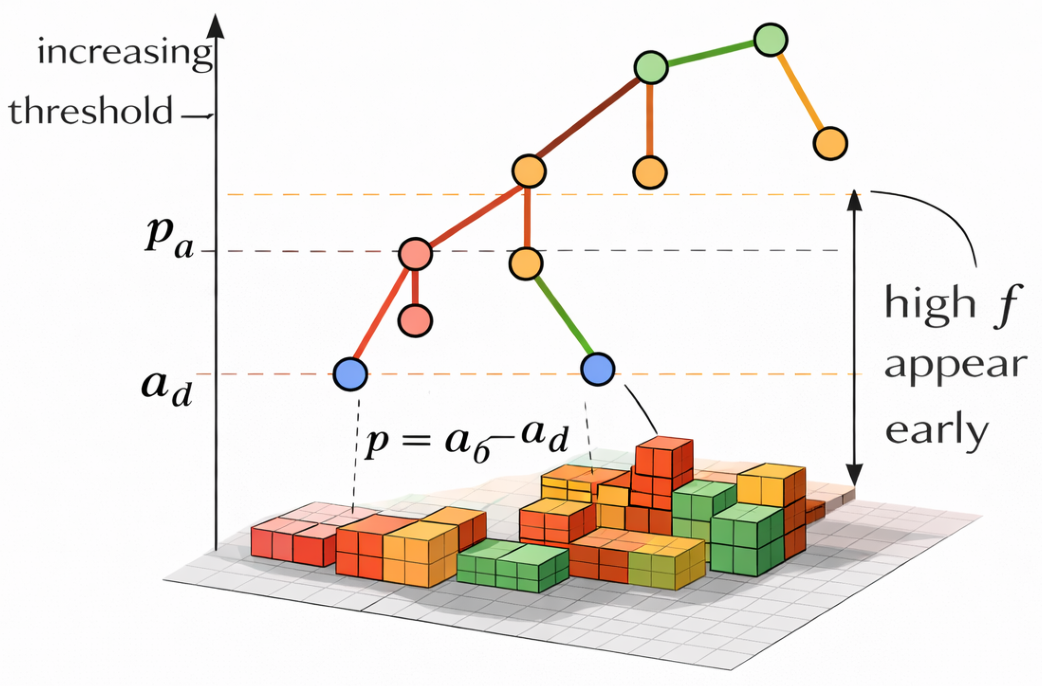
Figure A1 illustrates the merge-tree representation associated with a superlevel-set filtration, where the colours are used to distinguish different connected components and their successive merging levels.
Figure A1.
Merge tree associated with the superlevel-set filtration of a scalar field f. The tree , constructed from the sublevel sets of , encodes the hierarchy of connected components of the superlevel sets of f. Each branch corresponds to a connected component appearing at a local maximum of f at level and merging with a more dominant component at a critical level . The persistence is defined as and measures the lifetime of the component. The coloured nodes and branches are used to visually distinguish components and their successive merging events; they do not encode additional numerical values. The coloured blocks in the scalar field indicate regions belonging to the corresponding components at different filtration levels. The segment indicates the projection of the birth level, represents the birth-to-merge interval, and p corresponds to the persistence of the branch.
Appendix A.3.2. Reeb Graphs
Given , define an equivalence relation on K by
Reeb graph is the quotient space
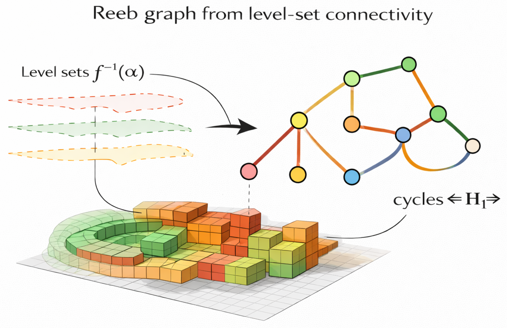
Unlike merge trees, Reeb graphs may contain cycles, reflecting splitting and reconnection events in level-set connectivity. Figure A2 illustrates the construction of a Reeb graph from the connectivity of the level sets of a scalar field, with colours used to distinguish the different connected components and their evolution across levels.
Figure A2.
Reeb graph associated with a scalar field f. The graph is constructed from the connectivity of the level sets , where each node represents a connected component of a level set and edges track its evolution as the level varies. Critical points of f correspond to branching or merging events in the graph. The coloured level curves and graph branches are used to visually distinguish the different connected components and their connections across successive levels; they do not encode additional numerical values. The Reeb graph provides a compact topological representation of the scalar field by encoding how connected components appear, merge, split, or disappear. In particular, loops in correspond to non-trivial one-dimensional homology classes (), capturing the presence of topological cycles in the underlying structure.
Appendix A.4. Merge Tree Segmentation
The merge tree induces a natural segmentation of the domain. Let denote the canonical projection mapping each cell to its connectivity lineage in the merge tree.
For each edge e of , we define the associated topological region
Family defines a partition of K, referred to in the main text as the merge tree segmentation.
Each region is associated with an interval in . Hence, the merge-tree segmentation provides a spatial localisation of zero-dimensional persistent homology classes.
Appendix A.5. Skeletons and Reeb-like Graphs
Let be a cubical subcomplex obtained by thresholding a scalar field. A topological skeleton of B is a one-dimensional cubical subcomplex obtained by homotopy-preserving reductions, such that S is a deformation retract of B.
Let and denote the vertices and edges of the skeleton. For a vertex , its degree is the number of incident edges. Vertices with are endpoints, while vertices with are junctions.
We define a graph
where consists of all endpoints and junctions, and consists of maximal paths connecting vertices in without intermediate branching. This graph provides a compact representation of the branching and connectivity structure of the skeleton.
In the present paper, the term Reeb-like graph refers to this skeleton-based discrete approximation rather than to the continuous Reeb graph in the strict topological sense.
Appendix A.6. Formal Definition of the Danger Map
Let be a filtration function and define . Let be the associated merge tree, and let denote the persistence-weighted field induced by the merge-tree segmentation.
Let S be a skeleton extracted from a dominant support. We define the skeleton proximity field by
where denotes the Euclidean or graph distance to the skeleton.
Given nonnegative coefficients such that , the topological danger map is defined by
This definition formalises the spatial indicator used in the main text. Its role remains descriptive and exploratory.
Appendix A.7. Formal Definition of the TDCI
Let
be the one-dimensional persistence diagram associated with the filtration f, and let
denote the corresponding persistence values.
We define three scalar descriptors:
and, for a threshold ,
Let be a finite set of ageing states. For each descriptor , we define the normalised quantity
where is a stabilising constant.
Given nonnegative weights with , the Topological Damage Complexity Index is defined by
Remark A1.
The TDCI is constructed solely from and is therefore independent of the merge-tree-based descriptors and of the danger map.
Appendix A.8. Stability Results
We now collect the stability statements used in the main text.
Proposition A1 (Stability of anisotropic filtrations).
Let K be a finite cubical complex and let be two scalar images. Let denote the anisotropic filtration functions constructed from I and via the structure tensor.
Assume that the eigenvalues of the structure tensor depend Lipschitz-continuously on the input image, i.e., that there exists such that
There exists such that
Proof.
The filtration functions and are rational expressions in the eigenvalues , regularised by . Under the stated Lipschitz assumption on the eigenvalues, the same property follows for by direct composition estimates. □
Theorem A1 (Stability of persistence diagrams).
Let be two tame functions on a finite cubical complex K. For any homological dimension ,
where denotes the bottleneck distance. The same inequality holds for all p-Wasserstein distances.
Proof.
Since K is finite and the filtrations are tame, the corresponding persistence modules are of finite type. The claim follows from the standard stability theorem for persistence diagrams; see [53,54]. □
Theorem A2 (Stability of merge trees).
Let be two tame scalar functions on a finite cubical complex K, and let and denote their merge trees. Then, with respect to the functional distortion distance , there exists a constant such that
Proof.
If , then the corresponding sublevel sets satisfy
The correspondence between the two sublevel-set filtrations therefore induces an -interleaving between the associated merge trees. The result then follows from the standard equivalence between interleaving distance and functional distortion distance for merge trees; see [55]. □
Lemma A1 (Stability under the superlevel-set convention).
Let and define and . Then
Proof.
Immediate from
□
Proposition A2 (Stability of the danger map).
Let be two tame filtration functions and define , . Assume that there exist constants such that
and
There exists a constant such that
Proof.
By definition,
The stated bound follows from the supremum norm estimate, the triangle inequality, and Lemma A1. □
Theorem A3 (Robustness of the TDCI components).
Let be two tame filtration functions and assume that
Under this assumption, the following stability properties hold:
- 1.
- the total persistence satisfies
- 2.
- the persistence entropy varies continuously, and is Lipschitz on sets where Σ is bounded away from 0;
- 3.
- for a fixed threshold , the count is locally constant as long as no persistence value crosses the threshold boundary.
These estimates show that the components entering the TDCI are stable under small perturbations of the persistence diagram.
Proof.
The bound for follows from the fact that, for each matched pair ,
Summation over all pairs in the matching gives the first statement.
The continuity of the entropy term follows from the continuity of after normalisation by , provided stays bounded away from 0.
Finally, if no persistence value lies exactly at the threshold , then sufficiently small perturbations cannot move a point across the set , so the count remains unchanged. □
Appendix B. Additional Results for F1 and F2 Across Ageing Stages
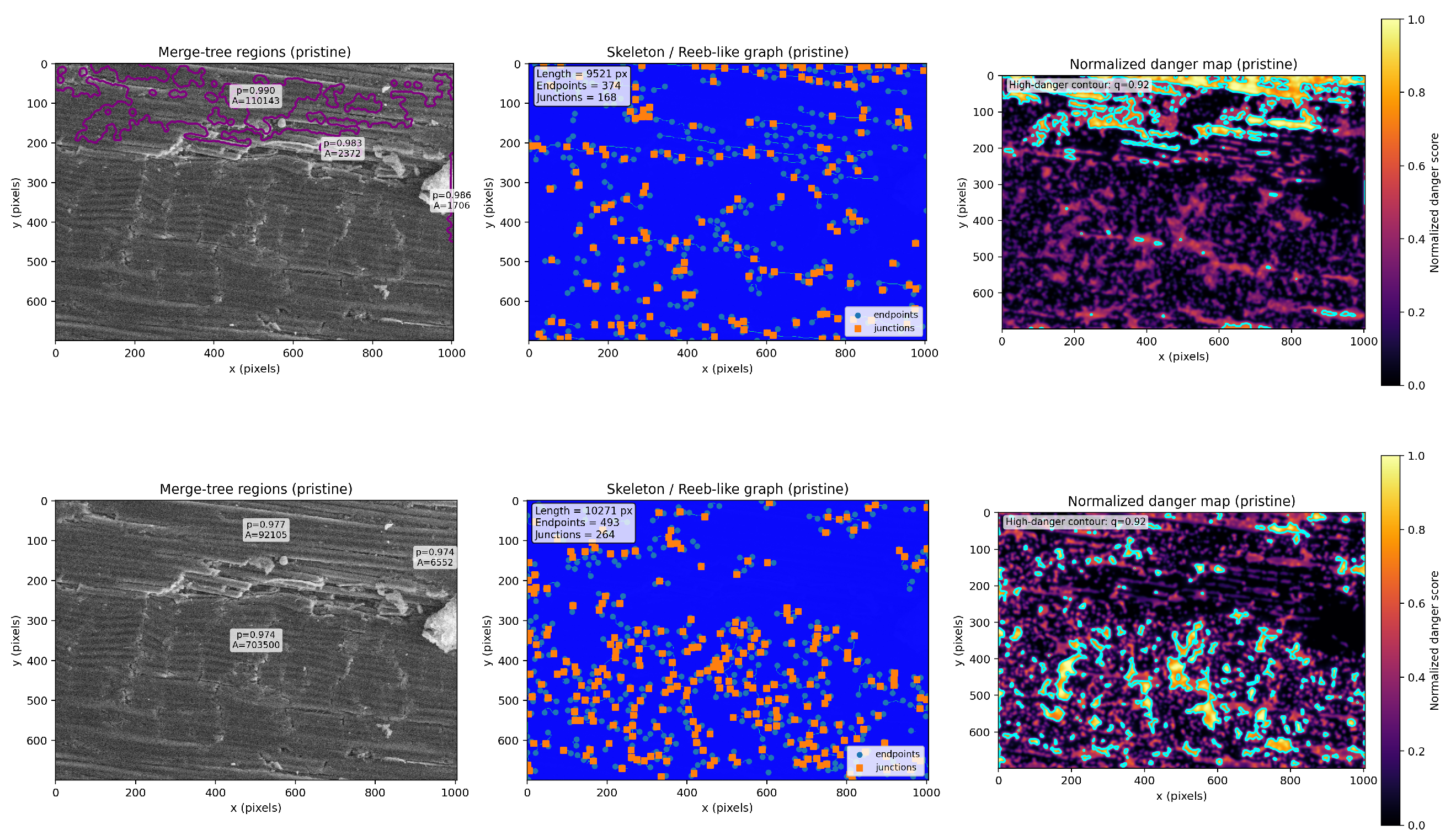
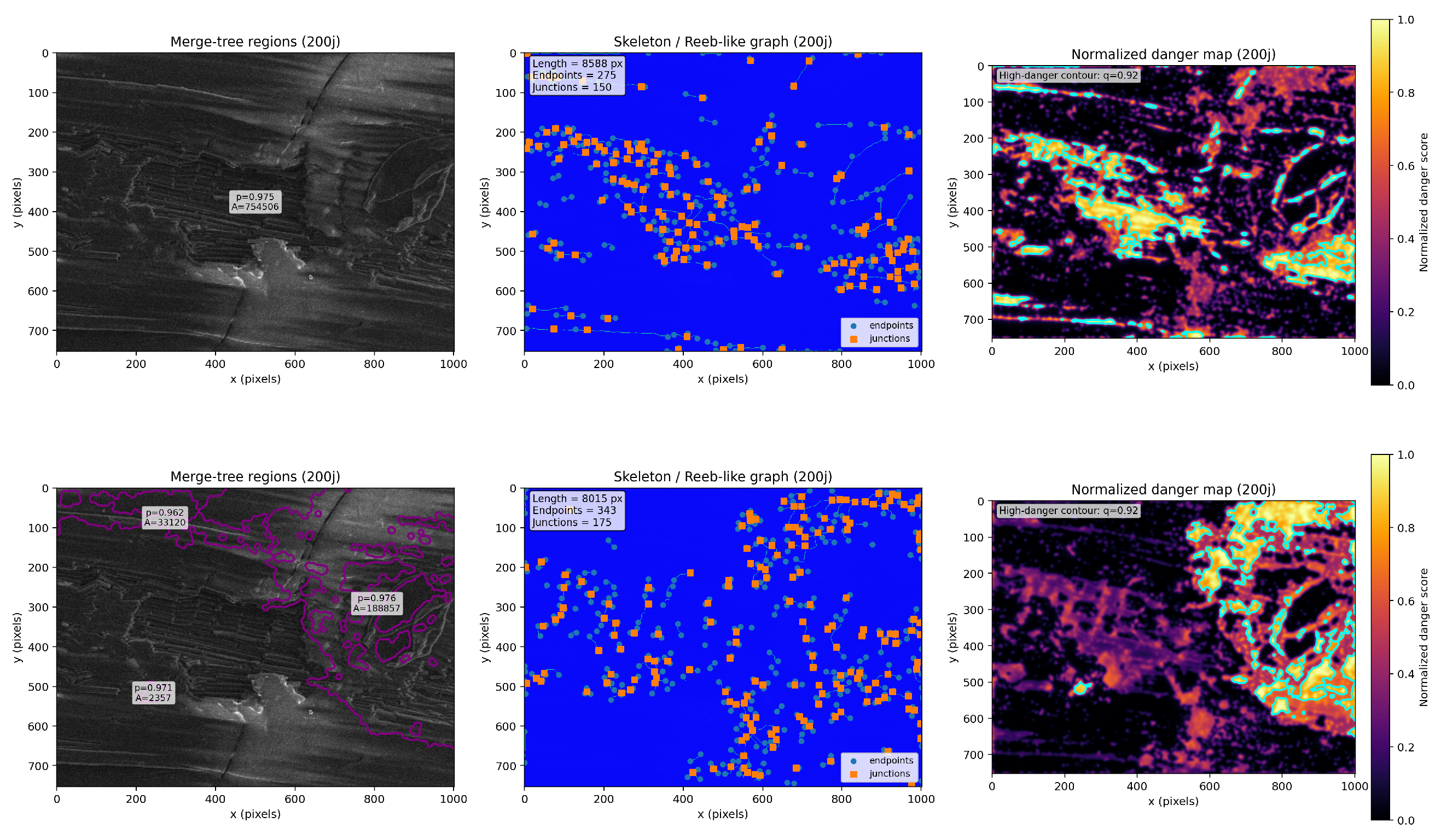
For completeness, we provide the full set of topological representations for all ageing stages (pristine, 200 days, and 650 days) and for both filtrations (fibre-oriented) and (crack-oriented).
Each configuration includes the merge-tree representation (), the associated skeleton (Reeb-like graph), and the normalised danger map. These supplementary figures support the quantitative trends reported in the main text.
Appendix B.1. Pristine State
Figure A3.
Topological representations for the pristine state. Top: filtration . Bottom: filtration . Each row shows merge-tree regions, skeleton (Reeb-like graph), and normalised danger map.
Appendix B.2. 200 Days
Figure A4.
Topological representations at 200 days. Top: filtration . Bottom: filtration .
Appendix B.3. 650 Days
Figure A5.
Topological representations at 650 days. Top: filtration . Bottom: filtration .
References
- Colin, X.; Verdu, J. Humid Ageing of Organic Matrix Composites; Springer: Dordrecht, The Netherlands, 2014; pp. 47–114. [Google Scholar]
- Bérot, O.S.; Hassoune-Rhabbour, B.; Acheritobehere, H.; Laforet, C.; Canot, H.; Durand, P.; Nassiet, V. Study of the hygrothermal aging of a phenolic matrix and glass fiber composite. J. Compos. Mater. 2025, 59, 2425–2437. [Google Scholar] [CrossRef] [Scilit]
- Abdessalem, A.; Tamboura, S.; Fitoussi, J.; Ben Daly, H.; Tcharkhtchi, A. Bi-phasic water diffusion in sheet molding compound composite. J. Appl. Polym. Sci. 2020, 137, 48381. [Google Scholar] [CrossRef] [Scilit]
- Xiao, G.Z.; Shanahan, M.E.R. Swelling of DGEBA/DDA epoxy resin during hygrothermal ageing. Polymer 1998, 39, 3253–3260. [Google Scholar] [CrossRef] [Scilit]
- Le Guen-Geffroy, A.; Le Gac, P.Y.; Habert, B.; Davies, P. Physical ageing of epoxy in a wet environment: Coupling between plasticisation and physical ageing. Polym. Degrad. Stab. 2019, 168, 108947. [Google Scholar] [CrossRef] [Scilit]
- Angrizani, C.C.; de Oliveira, B.F.; Lorandi, N.P.; Ornaghi, H.L., Jr.; Amico, S.C. Combined hygrothermal aging and mechanical loading effect on unidirectional glass/epoxy composites. Polym. Polym. Compos. 2022, 30, 09673911221095261. [Google Scholar] [CrossRef] [Scilit]
- Perreux, D.; Suri, C. A study of the coupling between the phenomena of water absorption and damage in glass/epoxy composite pipes. Compos. Sci. Technol. 1997, 57, 1403–1413. [Google Scholar] [CrossRef] [Scilit]
- Pierron, F.; Poirette, Y.; Vautrin, A. A novel procedure for identification of 3D moisture diffusion parameters on thick composites: Theory, validation and experimental results. J. Compos. Mater. 2002, 36, 2219–2243. [Google Scholar] [CrossRef] [Scilit]
- Pasupuleti, R.; Wang, Y.; Shabalin, I.; Li, L.Y.; Liu, Z.; Grove, S. Modelling of moisture diffusion in multilayer woven fabric composites. Comput. Mater. Sci. 2011, 50, 1675–1680. [Google Scholar] [CrossRef] [Scilit]
- Zhang, Y.M.; Liu, Y.P.; Hou, S.Z.; Geng, J.H.; Wang, P. Study on moisture absorption characteristics of glass fibre-reinforced epoxy resin material for composite insulators based on the 3d-fick model. High Volt. 2024, 9, 888–901. [Google Scholar] [CrossRef] [Scilit]
- Zhang, W.R.; Kazemi, E.; Arab, B.; Zhang, W.Z. Ageing of carbon fibre-reinforced polymers (cfrps) under hygro-thermal-salt conditions. J. Compos. Mater. 2025, 59, 3367–3379. [Google Scholar] [CrossRef] [Scilit]
- Lee, M.C.; Peppas, N.A. Water transport in graphite/epoxy composites. J. Appl. Polym. Sci. 1993, 47, 1349–1359. [Google Scholar] [CrossRef] [Scilit]
- Svetlik-Haley, S.; Karbhari, V.M. Humidity and immersion based hygrothermal aging of pultruded gfrp composites: Moisture uptake and diffusion. J. Compos. Mater. 2025, 59, 991–1011. [Google Scholar] [CrossRef] [Scilit]
- Gillet, C.; Splawski, W.; Aguirre, F.; Hassoune-Rhabbour, B.; Tchalla, T.; Nassiet, V. Use of karl fischer titration for the localized measurement of water content in frp composite aircraft parts removed from service. J. Compos. Mater. 2023, 57, 1495–1510. [Google Scholar] [CrossRef] [Scilit]
- Tsotsis, T.K. Considerations of Failure Mechanisms in Polymer Matrix Composites in the Design of Aerospace Structures; Elsevier: Amsterdam, The Netherlands, 2012; pp. 227–278. [Google Scholar]
- Demirci, I. Mécanique de L’endommagement par Rayure de Polymeres. Ph.D. Thesis, Universite Louis Pasteur Strasbourg, Strasbourg, France, 2004. [Google Scholar]
- Gauthier, C.; Lafaye, S.; Schirrer, R. Elastic recovery of a scratch in a polymeric surface: Experiments and analysis. Tribol. Int. 2001, 34, 469–479. [Google Scholar] [CrossRef] [Scilit]
- Chatel, T. Fluage et Recouvrance D’empreintes et de Sillons sur Surface de Polymere. Ph.D. Thesis, Universite de Strasbourg, Strasbourg, France, 2010. [Google Scholar]
- Bourrel, T. Influence des Longueurs Internes sur la Tenue Mecanique d’un Film Anti-Rayure. Ph.D. Thesis, Universite de Strasbourg, Strasbourg, France, 2017. [Google Scholar]
- Ni, B.Y.; Le Faou, A. Scratching behaviour of polymer films using blunt spherical styli. J. Mater. Sci. 1996, 31, 3955–3963. [Google Scholar] [CrossRef] [Scilit]
- Bora, M.O.; Coban, O.; Sinmazcelik, T.; Gunay, V. Effect of fiber orientation on scratch resistance in unidirectional carbonfiber-reinforced polymer matrix composites. J. Reinf. Plast. Compos. 2010, 29, 1476–1490. [Google Scholar] [CrossRef] [Scilit]
- Cheng, Q.; Jiang, H.; Li, Y.H. Effect of fiber content and orientation on the scratch behaviour of short glass fiber reinforced pbt composites. Tribol. Int. 2020, 146, 106221. [Google Scholar] [CrossRef] [Scilit]
- Edelsbrunner, H.; Letscher, D.; Zomorodian, A. Topological persistence and simplification. Discret. Comput. Geom. 2002, 28, 511–533. [Google Scholar] [CrossRef] [Scilit]
- Zomorodian, A.; Carlsson, G. Computing persistent homology. Discret. Comput. Geom. 2005, 33, 249–274. [Google Scholar] [CrossRef] [Scilit]
- Carlsson, G. Topology and data. Bull. Am. Math. Soc. 2009, 46, 255–308. [Google Scholar] [CrossRef] [Scilit]
- Edelsbrunner, H.; Harer, J. Computational Topology: An Introduction; American Mathematical Society: Providence, RI, USA, 2010. [Google Scholar]
- Ghrist, R. Barcodes: The persistent topology of data. Bull. Am. Math. Soc. 2008, 45, 61–75. [Google Scholar] [CrossRef] [Scilit]
- Lee, Y.; Barthel, S.D.; Dlotko, P.; Moosavi, S.M.; Hess, K.; Smit, B. Quantifying similarity of pore-geometry in nanoporous materials. Nat. Commun. 2017, 8, 15396. [Google Scholar] [CrossRef] [Scilit]
- Becker, S.; Devijver, E.; Molinier, R.; Jakse, N. Unsupervised topological learning for identification of atomic structures. Phys. Rev. E 2022, 105, 045304. [Google Scholar] [CrossRef] [Scilit]
- Suzuki, A.; Miyazawa, M.; Okamoto, A.; Shimizu, H.; Obayashi, I.; Hiraoka, Y.; Tsuji, T.; Kang, P.K.; Ito, T. Inferring fracture forming processes by characterising fracture network patterns with persistent homology. Comput. Geosci. 2020, 143, 104550. [Google Scholar] [CrossRef] [Scilit]
- Suzuki, A.; Miyazawa, M.; Minto, J.M.; Tsuji, T.; Obayashi, I.; Hiraoka, Y.; Ito, T. Flow estimation solely from image data through persistent homology analysis. Sci. Rep. 2021, 11, 17948. [Google Scholar] [CrossRef] [Scilit] [PubMed]
- dos Santos, K.R.M.; Rezaie, A.; Beyer, K. Topological data analysis-based damage indices for plastered stone masonry walls under cyclic loading. Eng. Struct. 2025, 322, 119088. [Google Scholar] [CrossRef] [Scilit]
- Nakagawa, A.; Delmotte, H.; Hallstrom, S.; Wan, Y.; Takahashi, J. Topology-constrained U-Net for delamination mapping in ballistic-damaged thin GFRP. Compos. Part B 2026, 311, 113240. [Google Scholar] [CrossRef] [Scilit]
- Carr, H.; Snoeyink, J.; Axen, U. Computing contour trees in all dimensions. Comput. Geom. 2003, 24, 75–94. [Google Scholar] [CrossRef] [Scilit]
- Biasotti, S.; Giorgi, D.; Spagnuolo, M.; Falcidieno, B. Reeb graphs for shape analysis and applications. Theor. Comput. Sci. 2008, 392, 5–22. [Google Scholar] [CrossRef] [Scilit]
- Morozov, D.; Weber, G. Distributed merge trees. In Proceedings of the 22nd International Symposium on High-Performance Parallel and Distributed Computing (HPDC), New York, NY, USA, 17–21 June 2013; pp. 93–102. [Google Scholar]
- Minamitani, E.; Shiga, T.; Kashiwagi, M.; Obayashi, I. Topological descriptor of thermal conductivity in amorphous materials. Phys. Rev. Mater. 2021, 156, 244502. [Google Scholar]
- Akagi, K.; Goto, M.; Xu, Y.; Wu, Y. Topological data analysis of TEM-based structural features affecting the thermal conductivity of amorphous Ge. Int. J. Heat Mass Transf. 2024, 221, 125012. [Google Scholar]
- Eguchi, R.; Wen, Y.; Abe, H.; Hashimoto, A. Interpretable Structural Evaluation of Metal-Oxide Nanostructures in Scanning Transmission Electron Microscopy (STEM) Images via Persistent Homology. Nanomaterials 2024, 14, 1568. [Google Scholar] [CrossRef] [Scilit] [PubMed]
- Obayashi, I.; Nakamura, T.; Hiraoka, Y. Persistent Homology Analysis for Materials Research and Persistent Homology Software: HomCloud. J. Phys. Mater. 2021, 4, 024003. [Google Scholar] [CrossRef] [Scilit]
- Uray, M.; Giunti, B.; Kerber, M.; Huber, S. Topological Data Analysis in smart manufacturing: State of the art and future directions. J. Manuf. Syst. 2024, 72, 456–472. [Google Scholar] [CrossRef] [Scilit]
- Uy, M.; Kido, D.; Kimura, M. A topological approach to understanding crack initiation and propagation in CFRP composites under an opening load. Sci. Rep. 2025, 15, 9217. [Google Scholar] [CrossRef] [Scilit]
- Canot, H.; Durand, P.; Frénod, E.; Hassoune, B.; Nassiet, V.; Tramis, O. Topological data analysis for roughness surfaces of bonding assembly. Discret. Contin. Dyn. Syst.-Ser. S 2025, 18, 1743–1766. [Google Scholar] [CrossRef] [Scilit]
- Gillet, C.; Hassoune-Rhabbour, B.; Poncin-Epaillard, F.; Tchalla, T.; Nassiet, V. Contributions of atmospheric plasma treatment on a hygrothermal aged carbon/epoxy 3d woven composite material. Polym. Degrad. Stab. 2022, 202, 110023. [Google Scholar] [CrossRef] [Scilit]
- Gillet, C. Etude du Vieillissement de Pieces en Materiaux Composites a Matrice Organique de Moteurs D’aeronefs et de ses Consequences sur leur Reparation Collee. Ph.D. Thesis, Institut National Polytechnique de Toulouse, Tarbes, France, 2022. [Google Scholar]
- Alston, S.; Korkees, F.; Arnold, C. Finite element modelling of moisture uptake in carbone fibre/epoxy composites: A multi-scale approach. In Proceedings of the 15th European Conference on Composite Materials (ECCM15), Venice, Italy, 24–28 June 2012. [Google Scholar]
- Zhou, J.M.; Lucas, J. The effects of a water environment on anomalous absorption behaviour in graphite/epoxy composites. Compos. Sci. Technol. 1995, 53, 57–64. [Google Scholar] [CrossRef] [Scilit]
- Grammatikos, S.A.; Zafari, B.; Evernden, M.C.; Mottram, J.T.; Mitchels, J.M. Moisture uptake characteristics of a pultruded fibre reinforced polymer flat sheet subjected to hot/wet aging. Polym. Degrad. Stab. 2015, 121, 407–419. [Google Scholar] [CrossRef] [Scilit]
- Weitsman, Y.J. Anomalous fluid sorption in polymeric composites and its relation to fluid-induced damage. Compos. Part A Appl. Sci. Manuf. 2006, 37, 617–623. [Google Scholar] [CrossRef] [Scilit]
- Ugochukwu, S.; Ridzuan, M.J.M.; Abdul Majid, M.S.; Cheng, E.M.; Razlan, Z.M.; Marsi, N. Effect of thermal ageing on the scratch resistance of natural-fibre-reinforced epoxy composites. Compos. Struct. 2021, 261, 113586. [Google Scholar] [CrossRef] [Scilit]
- Guermazi, N.; Elleuch, K.; Ayedi, H.F.; Zahouani, H.; Kapsa, P. Susceptibility to scratch damage of high density polyethylene coating. Mater. Sci. Eng. A 2008, 492, 400–406. [Google Scholar] [CrossRef] [Scilit]
- Tian, J.W.; Qi, X.; Xian, G.J. Effect of hygrothermal aging on the friction behaviour and wear mechanism of the multi-filler reinforced epoxy composites for coated steel. J. Mater. Res. Technol. 2024, 32, 140–151. [Google Scholar] [CrossRef] [Scilit]
- Chazal, F.; De Silva, V.; Glisse, M.; Oudot, S. The Structure and Stability of Persistence Modules; Springer: Berlin/Heidelberg, Germany, 2016. [Google Scholar]
- Cohen-Steiner, D.; Edelsbrunner, H.; Harer, J. Stability of persistence diagrams. Discret. Comput. Geom. 2007, 37, 263–271. [Google Scholar] [CrossRef] [Scilit]
- Bauer, U.; Munch, E.; Wang, Y. Strong equivalence of the interleaving and functional distortion metrics for merge trees. In Computational Geometry: Theory and Applications; Dagstuhl Publishing: Wadern, Germany, 2020. [Google Scholar]
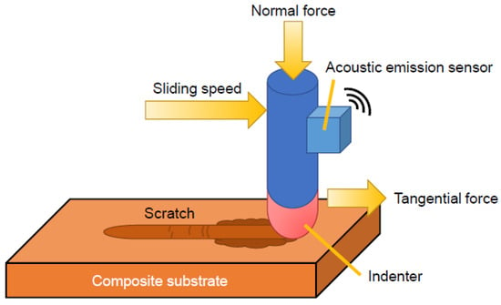
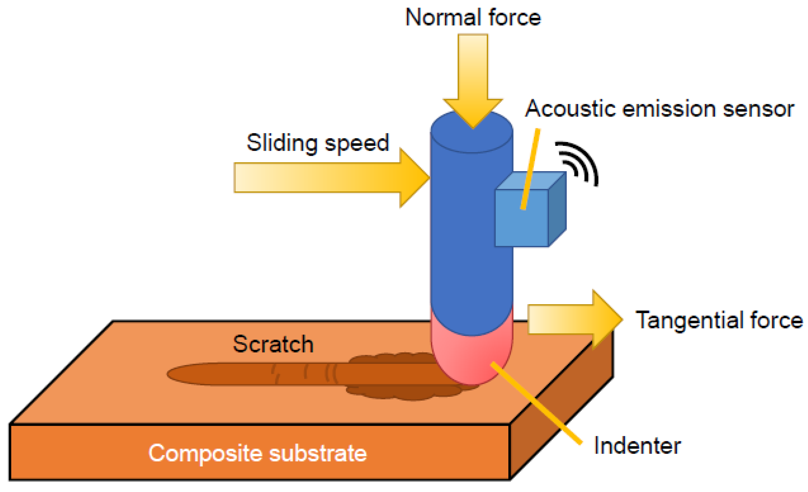
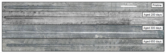
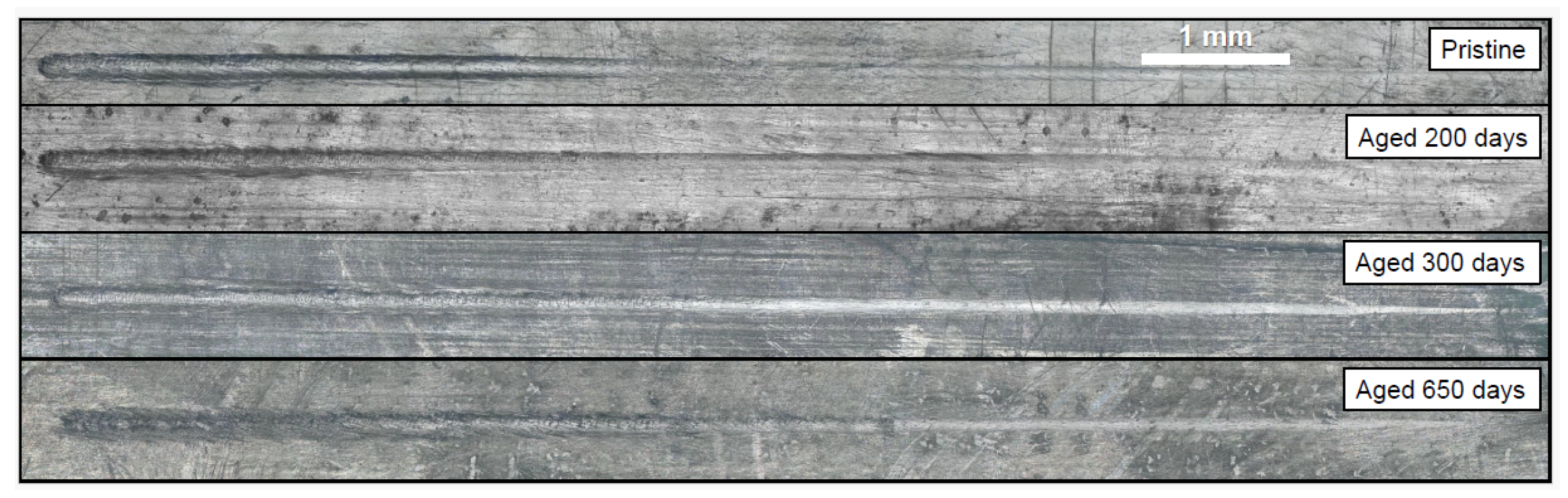
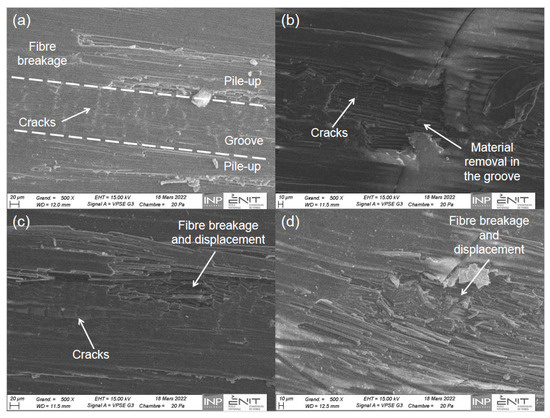
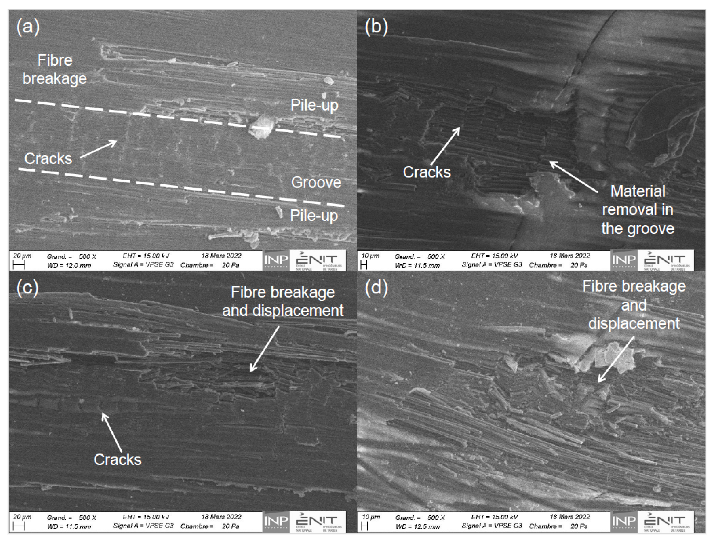
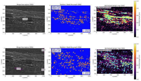
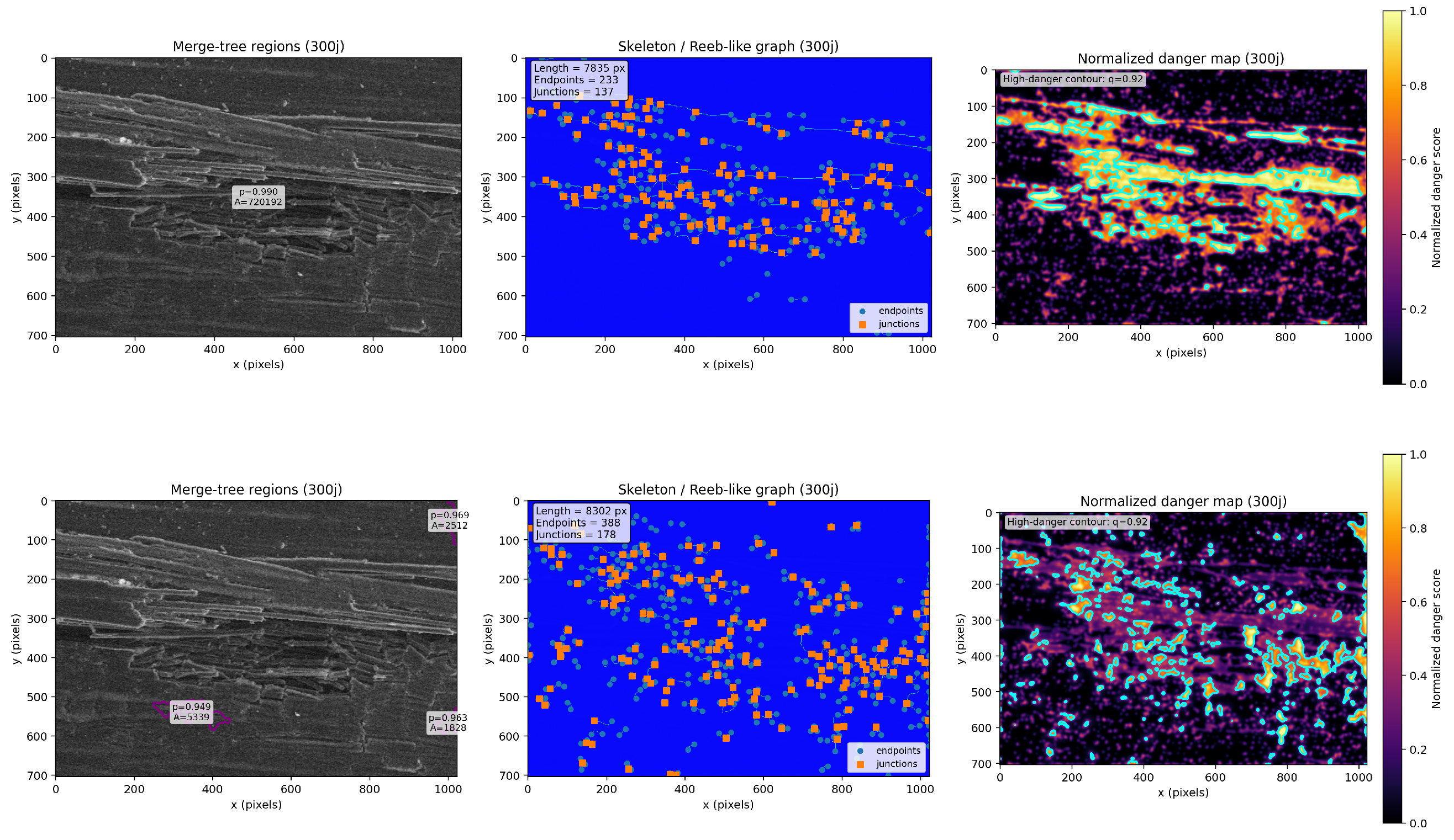
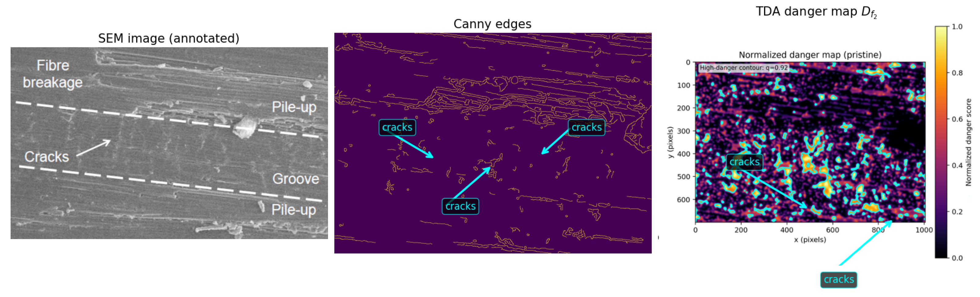
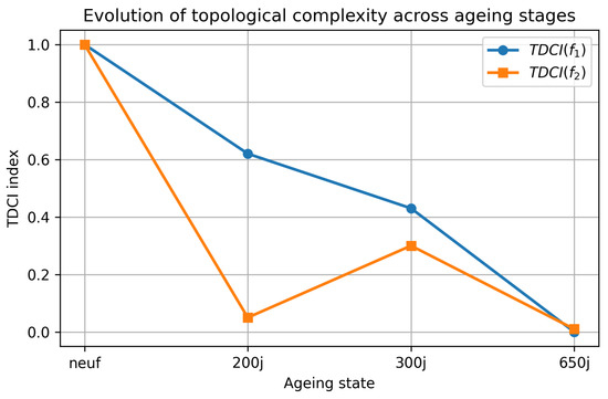
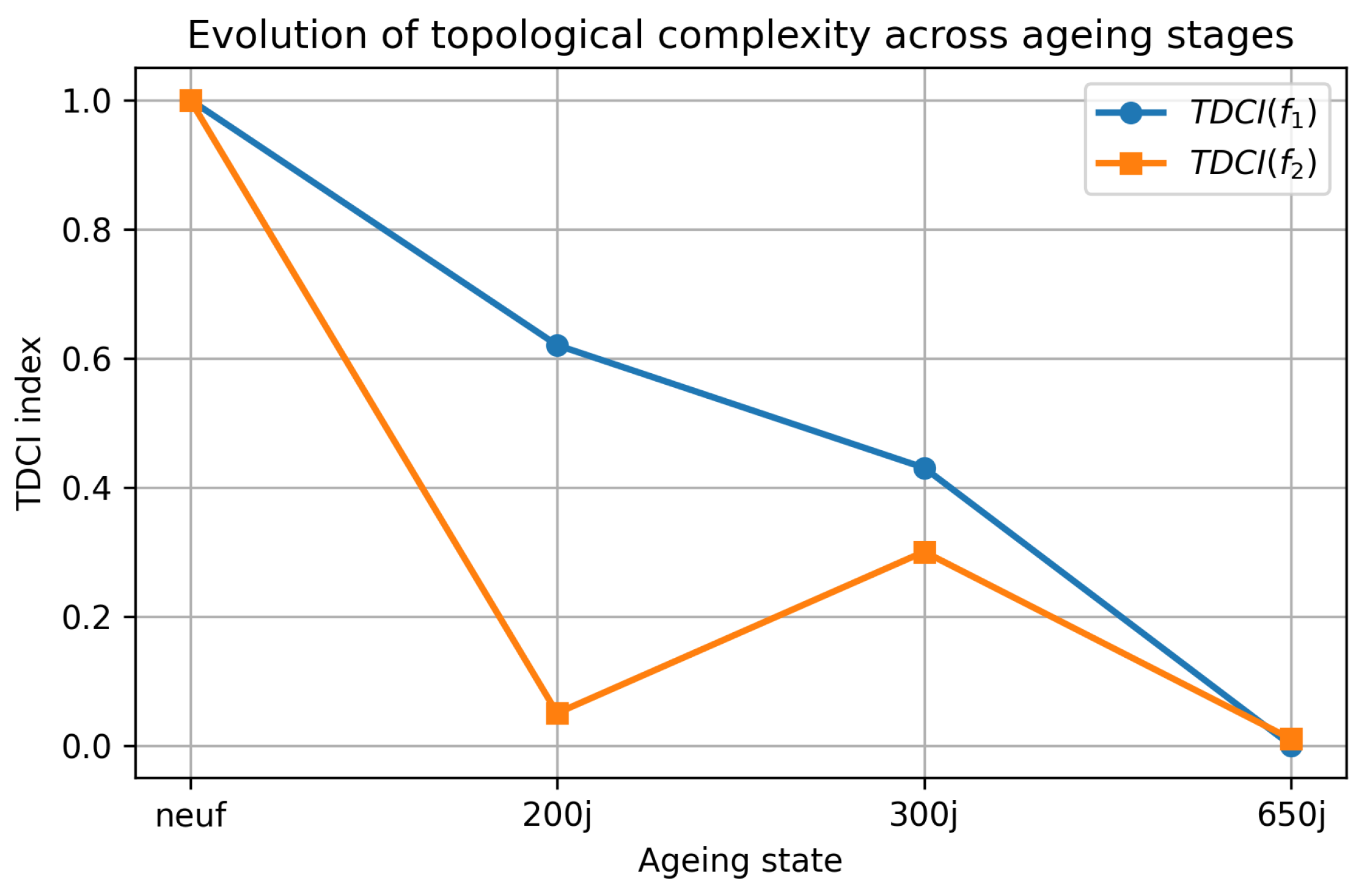
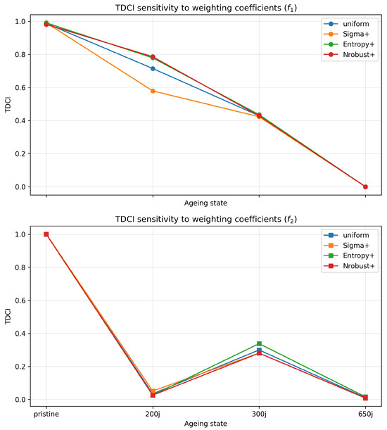
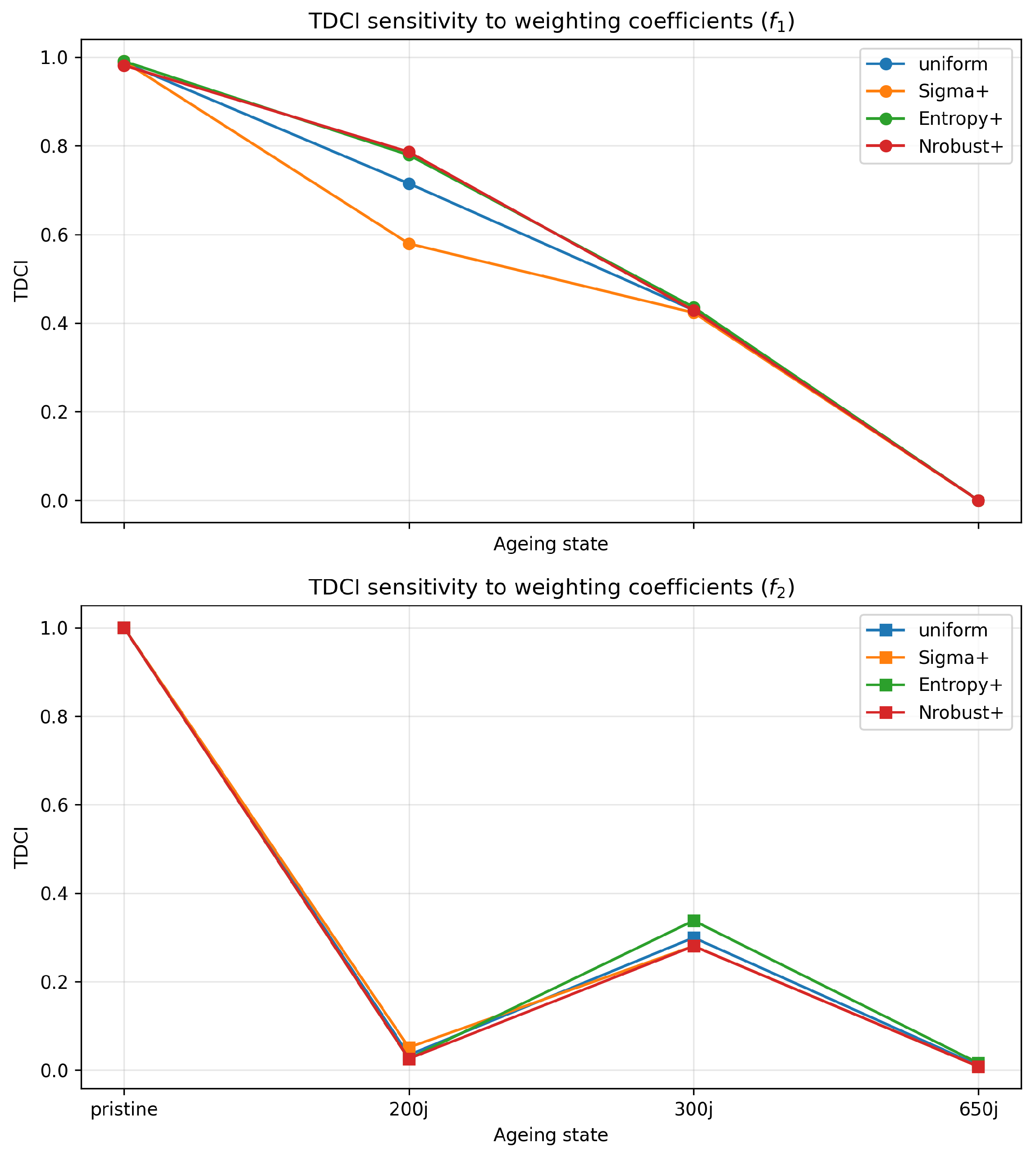
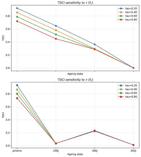
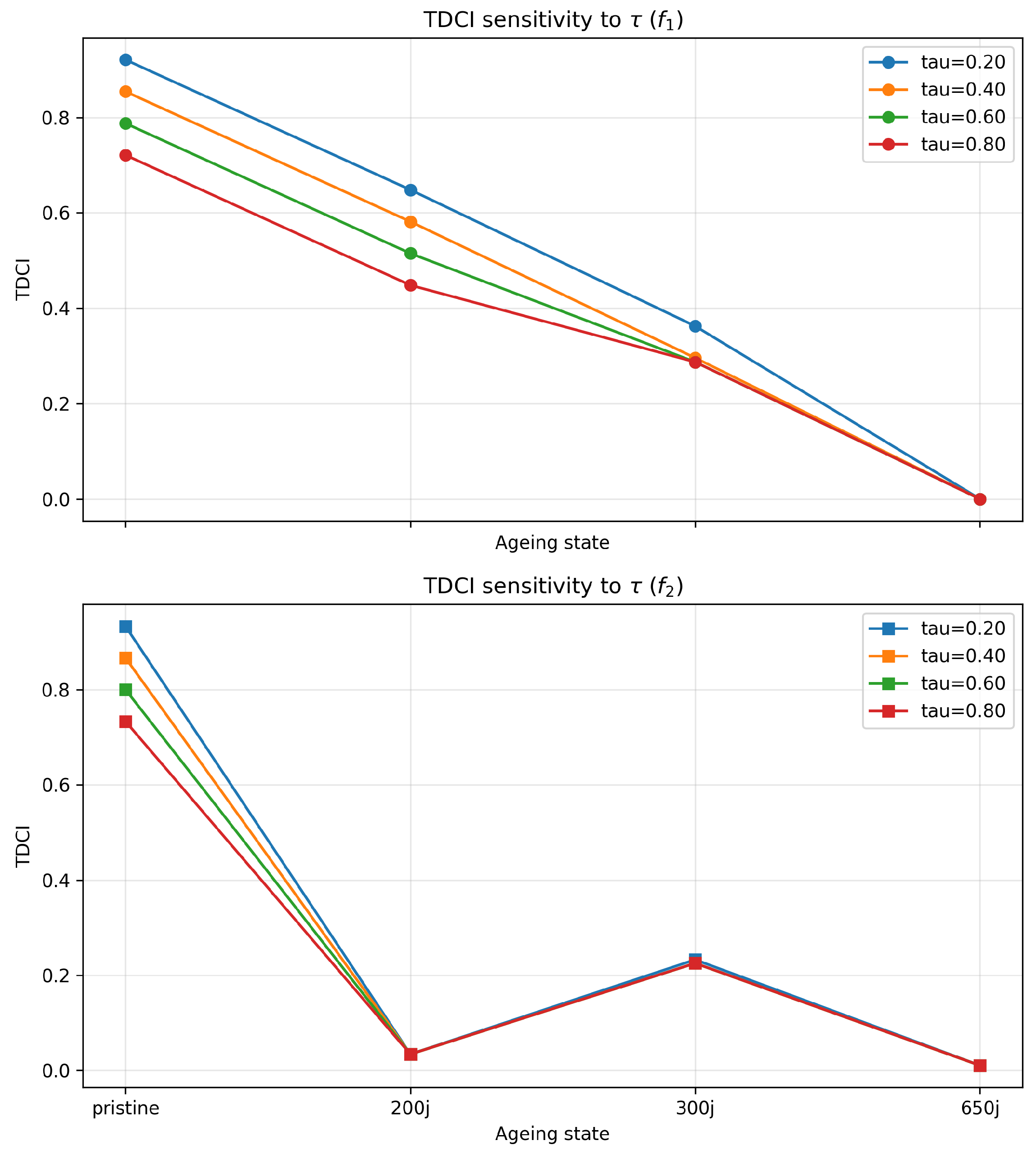
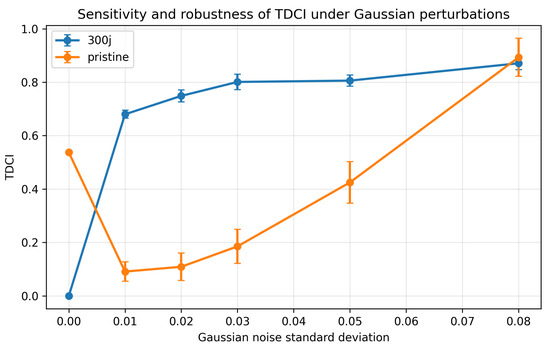
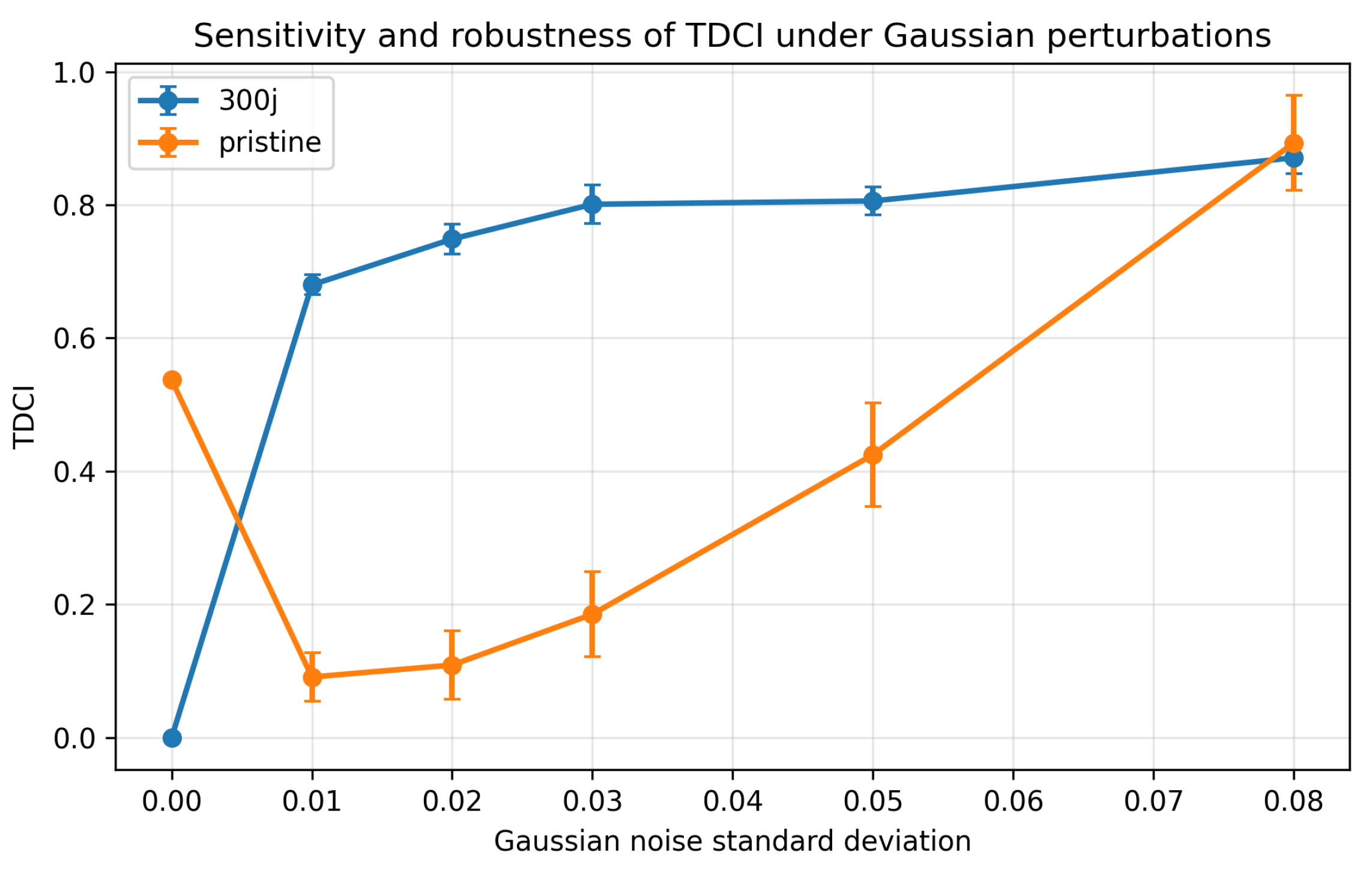

Disclaimer/Publisher’s Note: The statements, opinions and data contained in all publications are solely those of the individual author(s) and contributor(s) and not of MDPI and/or the editor(s). MDPI and/or the editor(s) disclaim responsibility for any injury to people or property resulting from any ideas, methods, instructions or products referred to in the content. |
© 2026 by the authors. Licensee MDPI, Basel, Switzerland. This article is an open access article distributed under the terms and conditions of the Creative Commons Attribution (CC BY) license.