


Abstract
Link congestion resulting from routine traffic patterns or malicious link flooding attacks (LFAs) poses a significant challenge in datacenter environments. The growing adoption of software-defined networking (SDN) offers a flexible framework for dynamic network reconfiguration, making it a promising approach for mitigating LFAs. Traffic redirection in SDN can follow either the shortest alternative path or a path that minimizes the number of rule modifications. The shortest alternative path sometimes yields a high number of changes in rules. As SDN switches are constrained by limited rule storage, a high number of rules may result in slow processing of the packet forwarding. Excessive rule updates can also degrade performance and introduce interruptions while the rules are being updated. This study focuses on minimizing rule changes when rerouting traffic away from congested links. We formulate two optimization problems aimed at reducing rule modifications during redirection. The first addresses a congested link and a specific flow, for which we propose solutions based on Dijkstra’s algorithm. The second extends to scenarios involving multiple congested links, introducing flow grouping and enhanced rule-merging strategies. To validate our approach, we conduct comprehensive simulations and real-world experiments within a datacenter setting.
1. Introduction
Link congestion within data centers has emerged as a critical issue in contemporary network environments. Link congestion may arise from routine network traffic or as a consequence of a link flooding attack (LFA). The LFA attack is one kind of distributed denial-of-service (DDoS) attack. The strategic approach and objectives of an LFA differ from those of a DDoS attack. In a DDoS attack, the malicious program or bots generate a huge amount of traffic destined for the victim. On the other hand, in LFA, an adversary aims to overwhelm an important link by generating useless traffic. The unnecessary traffic is directed toward decoy servers. The path that the packets traverse contains at least one critical link to reach the intended victim. These decoy servers, controlled by the attacker, serve solely as endpoints for receiving the unnecessary packets [1]. In severe cases, LFA disconnects a server or a network from the Internet. In modern datacenters, traditional routers are being replaced by software-defined networking (SDN) switches. Within the SDN framework, a centralized software known as the controller orchestrates the behavior of all connected switches in a network. This controller keeps a comprehensive overview of the network topology, link conditions, traffic flow metrics, and various other traffic attributes. A global view of the topologies helps the controller to optimize the network that was never possible with the traditional network architecture [2]. This centralized SDN architecture opened opportunities to mitigate link congestion and defend against LFA easily and effectively.
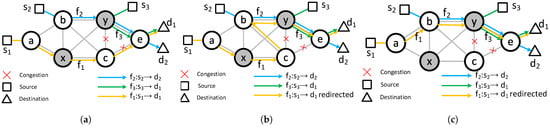
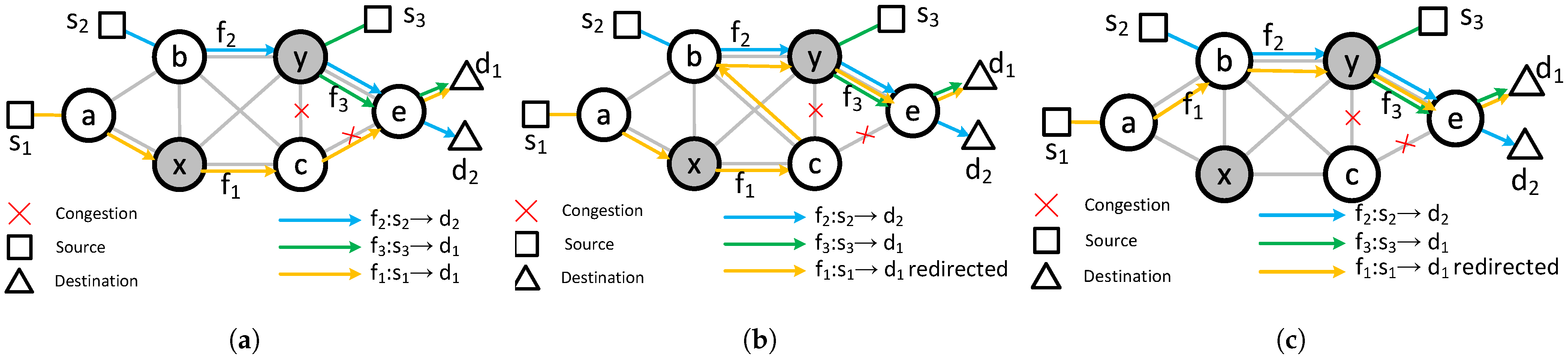
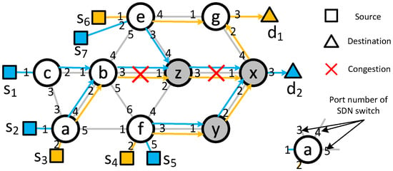
Consider the network illustrated in Figure 1a, which is comprised of four SDN switches (a, b, c, and e), two traditional switches/routers (x and y), three source nodes (, , and ), and two destination nodes ( and ). The network carries three flows: , , and . Links and experience congestion due to additional traffic or LFA, which are not depicted in the figure. To alleviate congestion, flow must be rerouted. Several redirection strategies with different redirection points are possible. A redirection point is defined as an SDN switch along the original path where the flow is diverted to an alternate route. For , potential redirection points include nodes a and c.
Figure 1.
Flow redirection due to LFA. (a) Initial network with two congested links. (b) redirected with two increased hops. (c) redirected with two increased rules.
When node a is selected as the redirection point, flow can be rerouted along the path . This requires installing new forwarding rules at nodes a and b, directing the flow toward b and y, respectively. Since the forwarding rule from y to e for is already there, only two additional rules are needed, and the hop count remains unchanged. Alternatively, if node c is chosen as the redirection point, flow can be routed via . In this case, a new rule is required at node c to forward to b. This approach adds one rule but increases the path length by two hops.
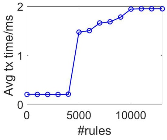
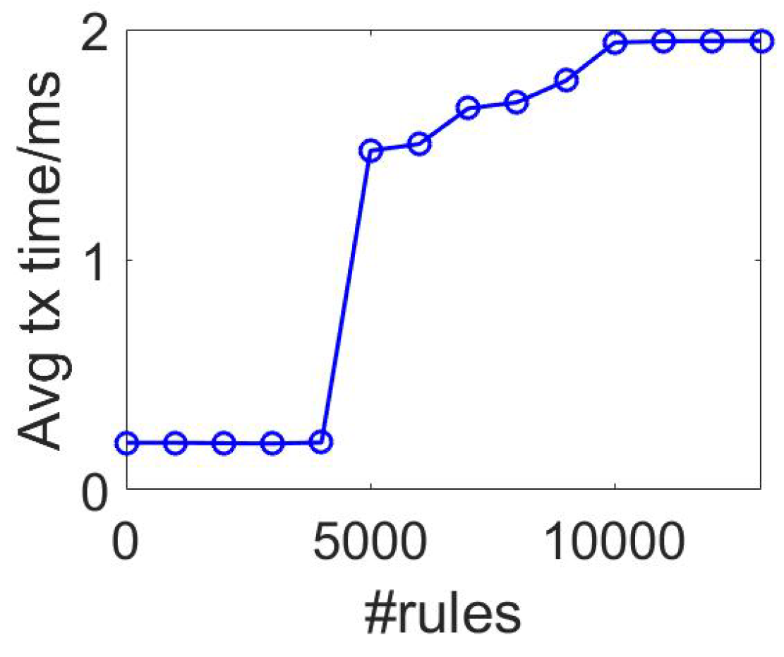
To highlight the impact of the quantity of rules, we carried out a preliminary experiment using a Pica8 P-3297 SDN switch in our datacenter. The results revealed that when the number of rules exceeds 4000 (refer to Figure 2), the transmission delay between two machines separated by two hops increases by approximately 1 ms. This latency spike occurs due to the depletion of the SDN switch’s fast-access memory. These findings underscore the significance of minimizing rule counts and have driven our deeper exploration into this area. Additional experiments investigating flow disruption caused by varying rule volumes are discussed later.
Figure 2.
Transmission time vs. the number of rules.
This paper addresses the challenge of mitigating link congestion through selective flow redirection. As the number of rules increases, the controller requires more time to implement changes, leading to potential flow interruptions. Moreover, when rule counts exceed the switch’s fast-access memory capacity, transmission delays intensify. To limit rule changes, flows may be routed along longer paths, which could marginally increase latency. However, this approach effectively reduces overall delay by avoiding overloaded switches and minimizing disruptions. To illustrate our solution approach, we first present a basic problem scenario involving a single congested link and one flow to be redirected. This introduces the concept of the core tree (CT) and employs a Dijkstra-based algorithm for resolution. We then extend the basic formulation to a more complex problem involving multiple flow redirections across multiple congested links. This is an NP-hard problem, and we propose a flow grouping-based solution. We use some classic clustering algorithms, including hierarchical and k-means clustering algorithms, to group the flows. Comprehensive simulations and experimental evaluations are conducted, and the results are compared against existing methods. The main contributions of our paper are:
- 1.
- We study flow redirection methods during link congestion or flooding attack via the minimum rule path to reduce interruption in the flow.
- 2.
- We introduce the concept of CT and use it to solve a basic flow redirection problem, considering a single flow and multiple congested links.
- 3.
- We propose a flow grouping-based redirection approach for multiple flows in the context of multiple links congestion.
- 4.
- Our extensive simulation, driven from the data obtained from datacenter experiments, supports the goal of our proposed approach.
The remainder of this paper is structured as follows. Section 2 reviews some previous relevant work. Section 3 describes the system architecture along with the attacker model. The flow redirection problems and their corresponding solutions are detailed in Section 4 and Section 5. Section 6 and Section 7 present the simulation setup and the experimental findings. Finally, Section 8 summarizes the work and outlines the concluding remarks. This research was supported in part by NSF grants CNS 2107014, CNS 2128378, CNS 1824440, CNS 1757533, CNS 1828363, CNS 1629746, and CNS 1651947. This research is an extension of our research published in [3].
2. Related Works
Networks with well-structured topologies can handle LFAs or link failures more easily. Their built-in redundancy and organized layout help with rerouting [4]. Irregular networks face different problems as they lack the same structural advantages. Research on defending against LFA and link congestion reduction in SDN falls into two main areas. The first area uses statistical detection methods, including correlation, entropy, covariance, divergence, cross-correlation, and information-gain-based techniques [5]. These methods aim to identify malicious traffic. The second area focuses on congestion control using multi-path routing and traffic redirection [1,6,7,8]. However, many of these solutions ignore the SDN switch constraints by overlooking limits on the number of flow rules.
In [9], the authors present a scalable hybrid SDN datacenter design. It combines both wireless and wired connections. They define a routing minimization problem to reduce the total number of rules installed in switches. They develop a heuristic algorithm to solve the problem. This algorithm selects paths that use both wired and wireless links. It also applies rule aggregation to further reduce the rule count. In [10], the authors address link failures by ensuring that traffic remains reachable if a single link goes down. They reroute affected traffic through SDN switches using pre-configured IP tunnels. Multiple backup paths are set in advance. This allows congestion to be relieved quickly after a failure.
Some other works, such as [11], consider the problem of minimizing the number of rules in SDN switches and propose a heuristic algorithm that creates a reduced representation of rules in the SDN switches in the network. They do not consider link congestion or an attack scenario. In [12], the authors propose a DoS attack on the controller and link by dynamically re-routing potential malicious traffic, adjusting flow timeouts, and aggregating flow rules. In [13], the authors proposed an efficient flow forwarding scheme and an intelligent encoding algorithm to minimize the number of rules. In [14], the authors present a two-phase routing strategy for SDN networks. The first phase minimizes active links via an ILP formulation, solved efficiently using a greedy heuristic. The second phase introduces a rule replacement technique leveraging idle timeouts to avoid flow table overflow in SDN switches. In [15], the authors propose a rule caching strategy for forwarding rules in SDN networks based on predicted link states. It aims to reduce the latency of traffic by making the rules quickly accessible. It monitors changes in network topology caused by node mobility and preemptively stores updated routing rules. This predictive caching improves responsiveness and reduces delays during network transitions.
Some studies, such as [11], focus on reducing the number of rules in SDN switches. They introduce a heuristic algorithm that produces a compact representation of these rules across the network. These works do not address link congestion or attack scenarios. In [12], the authors target DoS attacks to both the controller and network links. Their method reroutes suspected malicious traffic dynamically. It also adjusts flow timeouts and aggregates flow rules to limit the attack’s impact. In [13], the authors present an efficient flow-forwarding method. They also design an intelligent encoding algorithm aimed at further reducing the number of rules in the network.
In [16], the authors propose a traffic rerouting strategy designed to provide immediate, temporary relief to overloaded target links during an LFA. This approach ensures that rerouting decisions are made to minimize disruption to overall network performance. To achieve a more permanent solution, they further introduce a traffic filtering mechanism based on behavioral analysis, aimed at identifying and eliminating malicious traffic patterns at their source. In [17], the Service-Priority-based Mitigation (SPM) method is used to detect and counter LFA in SDN. It monitors host behavior during congestion using flow table data. Machine learning models analyze these behaviors to identify malicious hosts. SPM then applies a dual-phase defense: rapid mitigation to limit damage and slower detection to minimize disruption to legitimate users.
In [18], the authors study scenarios with multiple link failures in an SDN network. They also address the challenge of rerouting multiple flows. Their work introduces a model to capture the communication overhead between the controller and switches during rerouting. The goal is to reduce the number of flow rules. They formulate the problem as a 0-1 nonlinear programming model. The solution uses a decomposition method based on Lagrange relaxation. In [19], the authors focus on multicast routing for multiple multicast requests. Their objective is to minimize the number of rules. They formulate the problem as an integer linear programming (ILP) and solve it with standard ILP solvers. In [20], the authors also use an ILP approach. They aim to minimize the total cost. All of these methods rely on integer linear programming to obtain solutions.
We reviewed three main types of existing LFA or link congestion defense systems. The first type of system detects attack packets or flows at a router. It then drops packets, applies rate control, or redirects traffic. This method increases the router’s processing load. False positives can also harm legitimate users. Bots can mimic normal traffic, making them hard to detect with statistical methods. The second type uses statistical or heuristic techniques to reroute traffic and avoid congested links in some specific scenarios, but fails in most regular attack scenarios. The third type of system selects and redirects flows using linear programming methods. This approach becomes slow when the network topology is large or complex. Therefore, a better solution is needed to reduce the number of new rules with low time complexity.
3. System Model
This section outlines the network architecture and the attacker model considered in this study.
Network Model
Our network consists of SDN switches, traditional routers, source nodes, and destination nodes. We consider that the controller knows both the attacked or congested links and the routing policies governing traditional routers and SDN switches. Additionally, the controller maintains a comprehensive view of the network topology and the forwarding rules in each of the SDN switches. In SDN switches, each rule represents a packet forwarding policy. Incoming packets are evaluated against rule matching criteria, such as the source address, destination address, and incoming port. Actions are executed based on the matched rule. An action decides which port will be used to forward the incoming packet. For simplicity, we focus on the destination address as the primary matching criterion. Unlike traditional routers, SDN switches allow the controller to dynamically add, modify, or remove forwarding rules. In cases where one or more links become congested due to normal or malicious traffic, affected flows must be rerouted through alternative non-congested paths. Redirection must ensure that no links remain congested afterward.
Flow redirection requires the controller to update or insert forwarding rules within selected SDN switches. Instead of modifying a rule, it is safe to add a new rule with a higher priority in an SDN switch. SDN rules are added with a validity period. If a rule is unused during the validity period, then it is evicted by the switch. SDN switches have limited memory for storing rules. A high number of rules can lead to significant delays in packet forwarding. Adding a new rule also introduces latency. If many rules are added or changed concurrently, it may disrupt ongoing flows. The sequence in which the controller sends rules does not impact this disruption. Rules are only installed when a relevant packet arrives at the switch. To avoid delays and interruptions, we focus on reducing the number of rules required to reroute flows from the congested links.
Let us assume that, flow from source s travels through path to destination d. Here, is the ith node on path and P is an ordered set. Each of the nodes in P has a rule for forwarding the packets in flow f. Let be the set of rules needed to forward the packets of f. where R is the set of rules for all flows in the topology. We will use the superscript f when it is necessary; otherwise, we will omit the superscript. Rule resides in SDN switch and forwards the packets of f to node through the link . Some of the nodes in P are SDN switches, and some of them are traditional routers. After redirection, the flow f travels through a new path . The new set of rules is is the set of rules needed to forward the packets in f through . Therefore, the new rules are represented by . These newly added rules must be installed in SDN switches. Traditional routers do not support rule insertion by the controller. Our goal is to keep the total number of added rules () as low as possible.
Our proposed system operates through four distinct phases. In the first phase, the controller identifies congested network links. In the second phase, it selects appropriate flows and alternative paths for redirection. In the third phase, the controller updates the forwarding rules on the SDN switches accordingly. In the final phase, it removes any redundant or unnecessary flows from the switches to optimize performance. The second phase is more challenging and complex compared to the other three phases. Our focus on minimizing interruption is in the second phase of the system.
4. Redirecting a Flow
In this subsection, we formulate a problem to redirect a flow with the minimum number of added rules. This problem is the basis of the complex problem of selecting and redirecting multiple flows. For simplicity, we assume that the controller knows the flow to redirect and the links that the new path should avoid.
Problem I: Find a route to redirect a flow so that the number of new rules needed is the minimum.
Let be the path of the flow . R is the set of rules needed to forward f through P. Let the links on the path P be congested. After redirection, the new path is . denotes the set of rules needed to forward packets of the flow f through . In this case, the problem can be expressed as the following optimization problem:
Here, the first constraint limits the length of the new path. The new path can be at most longer than the old path. The second constraint blocks the congested link from appearing in the new route and ensures that redirected flows do not pass through any congested links after rerouting. Here, is the maximum bandwidth allowed on the congested link. The term refers to the bandwidth usage on link .
4.1. A Dijkstra-Based Solution
The Problem I forms the foundation of Problem II, introduced in Section 5. It is relatively simple to solve. Such a scenario may occur when a high-volume flow overloads a single link. We present the solution here as a starting point for addressing Problem II.
To address the problem, the controller builds a CT for the flow’s destination node. A CT is a minimum spanning tree that covers all the destinations with all the sources. The cost of forwarding at each node in the tree is the minimum number of new rules required to reach the destination. Each node in the CT stores the next-hop information, including the number of rules needed to forward the flow through that node to the destination. The flow can be rerouted from any upstream SDN switch remaining on the flow path. Redirecting the flow to any node on the CT ensures delivery of the packet to the destination. To build a CT, the controller gathers all forwarding rules related to the flow being redirected.
Algorithm 1 shows the complete algorithm for creating a CT. The complexity of Algorithm 1 is (same as the Dijkstra algorithm) where and are the number of edges and vertices, respectively. Procedure FIND-CT is designed to construct a CT in a topology graph (where V, E, and represent the nodes, links, and routing rules, respectively) for a destination d while avoiding congested links . Algorithm 1 constructs a CT rooted at the destination node of the flow. It begins by initializing cost, distance, and rule sets for all nodes. Initially, the destination’s cost is set to zero. The algorithm iteratively explores neighboring nodes, excluding congested links from consideration. It updates their cost based on whether existing forwarding rules can be reused or new rules must be added, favoring paths that minimize the need for new rules. Using a priority queue, the algorithm selects the node with the minimum cost for updating. The resulting CT guarantees that any upstream SDN switch can redirect the flow to the destination while avoiding congestion and minimizing the number of new rules.
| Algorithm 1 Generate CT |
| Input: , congested links , destination d. Output: A CT of G for destination d.
|
4.2. An Example of a Dijkstra-Based Solution
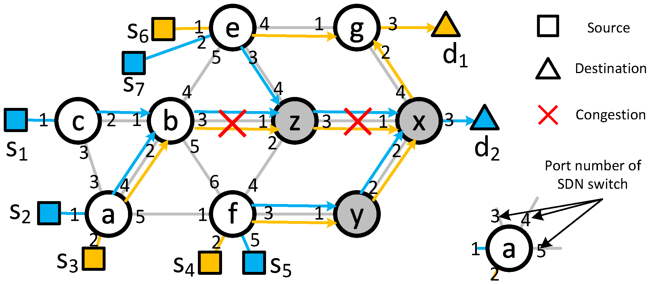
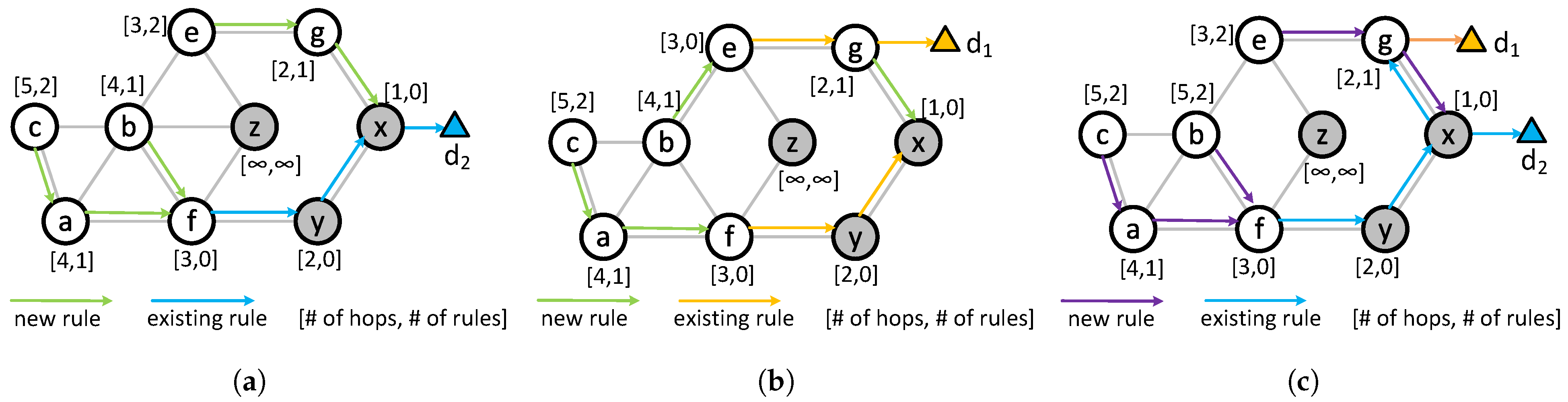
Consider the example illustrated in Figure 3. Assume that the links and are congested, and the flow needs to be redirected. This flow can be rerouted from node b or c. This is because nodes b and c remain on the path of before encountering any congestion. To determine the optimal redirection point, we first construct the CT for the destination node . Figure 4a presents the CT for . We begin by removing the congested links from the topology. Next, we compute both the number of hops and the number of forwarding rules required to deliver any flows to . We apply the Dijkstra algorithm to determine the minimal rule path from each node, excluding any links that would become congested when carrying the flow . Unlike Dijkstra, the number of rules takes precedence over the number of hops in the formation of CT. In Figure 4a, the blue arrows represent the existing rules and the green arrows represent the newly added rules. The hop count and number of rules needed are shown beside each of the nodes. For example, beside node b represents that the minimum number of rules needed to forward the packets to is 1, and the destination is 4 hops away. The CT also incorporates flow data rate constraints. For instance, when redirecting a flow of 10 Mbps, only links capable of handling an additional 10 Mbps without congestion are considered viable. From the constructed CT, we observe that redirecting from node c would require 2 new rules, while redirecting from node b would require only 1. Therefore, the flow will be redirected from b by installing a new rule at b that will forward the packets to node f if the destination is .
Figure 3.
Network topology. The numbers beside each link on an SDN switch represent the port number the link is connected to.
Figure 4.
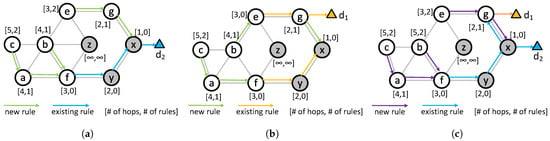
An example of the formulation of the CT. [# of hops, # of rules] by each SDN switch represents the number of minimum rules needed to forward the flow to the destination and the number of hops the flow will travel from that node to reach the destination. (a) CT for . (b) CT for . (c) CT for both and .
5. Redirecting Multiple Flows
In this section, we formulate a problem to redirect multiple flows with the minimum number of new rules.
Problem II: Find a set of flows to redirect from all flows passing through a congested link by adding the minimum number of rules.
In this problem, we assume that the controller is aware of the congested links. Let F be the set of flows passing through the congested links . We divide F into and . Flows in will continue using the congested link. Flows in will be redirected. Let be the new path of the flow f ().
Let F be the set of flows that pass through the congested link . This set is divided into two subsets: and . Flows in will continue on the congested link while flows in will be rerouted. For , let be the new path of the flow f.
In this scenario, we represent the task as an optimization problem. The objective is to find the minimum additional rule path under some constraints. The following is the formulation of the stated problem.
The set includes all rules required to reroute the flows in . If a rule is used to forward multiple flows, it appears in more than one rule set. To avoid duplication, we take the union of all individual rule sets. The term refers to the usage of bandwidth on the link . The parameter defines the maximum bandwidth allowed on the congested link. In other words, any traffic higher than the total bandwidth would make the link congested. The first constraint limits the new path length to at most more than the original. The second constraint prevents the congested link from being part of the new path. It also ensures that the redirected flows do not pass through any other congested links after rerouting or do not become congested for carrying newly redirected traffic.
5.1. A Flow Grouping Solution
The problem is NP-hard as it can be mapped to the knapsack problem. We propose a heuristic approach to address it efficiently. Our strategy focuses on grouping flows and applying optimized forwarding rules to each group, thus enhancing scalability and reducing run-time complexity. Flows are clustered based on upstream path similarity. Specifically, we consider the flow paths up to k hops toward the source from the congested link. Flows that share identical paths within this segment are assigned to the same group. This ensures that all flows in a group follow a common upstream path of length k. Each node along that path serves as a potential redirection point. Since a group has a common upstream path, it may be aggregated and forwarded by a rule in a node. Once the groups of flows are formed, we construct a CT for the set of destinations in each group. Creating a CT for a flow group is basically merging the CTs for the destinations in that group. During the merging process, we compute the required number of forwarding rules and evaluate the hop counts to each destination. A node can forward packets belonging to a destination group via two distinct mechanisms:
- 1.
- Separate forwarding: The node sends each flow’s packets to different next hops that require the minimum number of rules. When using separate forwarding, the total number of rules at the node is the combined count of distinct rules from all the CT being merged.
- 2.
- Aggregated forwarding: The node sends all packets intended for any destination in a group to one next hop. In aggregated forwarding, a single rule can handle all these packets. So, the total number of rules needed is one plus the smaller value between separate or aggregated forwarding across all CTs at the next hop nodes.
We choose the option that uses the minimum number of rules. If multiple options need the same number of rules, we pick the one with the shortest path.
For each group, we find the minimum number of rules needed to redirect the flows from a chosen redirect point by building a CT for that group of destinations. So, the number of CTs matches the number of groups. Next, we select the group with the lowest rule count and perform redirection. After that, we update the CTs of the remaining groups, since redirection can change link capacities. These changes may affect how the other CTs are formed. We repeat this process until the congested link is no longer congested. The full method for merging multiple CTs is shown in Algorithm 2.
| Algorithm 2 Merge CTs |
| Input: Topology graph , congested links , destinations set D. Output: A CT of G for destination set D.
|
This procedure MULT-DEST-CT is designed to construct a CT in a topology graph (where V, E, and represent the nodes, links, and routing rules, respectively), effectively merging individual CTs for multiple destinations while avoiding congested links . It starts by generating separate CTs for each destination using a procedure called (Algorithm 1). Then, it initializes all nodes with infinite cost and depth, and an empty rule set. The algorithm removes congested links from the edge set and processes nodes iteratively, selecting the one with the minimum cost from a queue. For each selected node, it updates costs, the rule set, and the maximum hop count for the destinations. It compares the number of rules needed in separate forwarding and aggregated forwarding methods and picks the method with the minimum number of rules. In the end, it returns a new CT graph , combining all the CTs for each destination.
The value of k is important for forming groups. When k is small, it creates fewer groups, but each group size is larger. This helps the algorithm run the computation faster, though bigger groups might require more rules to handle redirection.
5.2. An Example of Common k-Links Grouping
Consider the example in Figure 3. We assume that each link has a maximum capacity of 100 Mbps. Flows and their bandwidths are shown in Table 1. We can observe that flows , , , and pass through the link . Their total bandwidth is Mbps. We assume that any link utilization above (70 Mbps) is considered congested. Therefore, the link is congested in our example. Similarly, the link is also congested. We need to redirect some of the links among , , , and to make link usage less than or equal to 70 Mbps, avoiding any other congested links such as .
Table 1.
Flows and bandwidth.
Next, we group the flows according to the Common k-Links policy. Let us consider first. The upstream path of the flows of length 1 is as follows:
We can observe that , , and have the same upstream path . Therefore, flows , , and goes to group 1 and goes to group 2.
Next, we construct the CT for the groups . The CT for group 1 contains routes for destinations and . The total bandwidth of the group is . Therefore, any link having existing flows cannot redirect all of the traffic. If a link carries traffic, then adding 70 Mbps of traffic from group 1 would make that link congested. As a result, group 1 cannot be redirected together. However, separate forwarding may work in this case. As the CT for group 1 contains routes for destinations and , it is the same as in Figure 4c. The redirect point of group 1 is b. The number of rules needed to redirect from b is 2, but it uses the aggregated forwarding at b. Therefore, group 1 cannot be redirected from b. On the other hand, the CT for group 2 contains only routes to the destination . Therefore, the CT is the same as that in Figure 4a. The redirect point of group 2 is e. The number of rules needed to redirect from e is 2. Therefore, the minimum number of rules to redirect the flows in group 2 is 2. At this point, we redirect the flows in group 2, and the number of rules needed is 2. After redirection, the usage of the congested link becomes Mbps and is no longer considered congested.
If we consider , the upstream paths of the flows of length 2 are the following:
Now we have a different grouping for than for . Therefore, the flow goes to group 1, , and goes to group 2, and goes to group 3. The CT for group 1 contains routes for destination only. Therefore, the CT is the same as that in Figure 4a. The redirect points of group 1 are c and b. The number of rules needed to redirect from b and c is 1 and 2, respectively. The minimum number of rules to redirect the flows in group 1 is 1 and will be redirected from b.
The CT for group 2 contains routes for destinations and . Therefore, CT is the same as in Figure 4c. The possible redirect points of group 2 are a and b. The number of rules needed to redirect from a and b is 1 and 2, respectively. So, the minimum number of rules to redirect the flows in group 2 is 1 and will be redirected from b.
The CT for group 3 contains routes for destination only. Therefore, CT is the same as in Figure 4a. The redirect point of group 3 is e only. This is because z is a traditional router and cannot be redirected from there. The number of rules needed to redirect from e is 2. Therefore, the minimum number of rules to redirect the flows in group 3 is 2.
Therefore, redirecting group 2 adds the least number of rules. We redirect the flows and from node a. After redirection, the link capacity of the congested link decreases to Mbps, which is below of link utilization, and the algorithm stops.
Theorem 1.
The complexity of Algorithm 2 is .
Proof.
To calculate the complexity of Algorithm 2, we need to calculate the complexity of Algorithm 1. Algorithm 1 is the Dijkstra algorithm. Therefore, the complexity is where and . Step 2 in Algorithm 2 takes . Step 12 takes times because at any node, the number of added rules can be at most the number of destination nodes. Therefore, the while loop in Step 5 takes time. So, the total run time of the Algorithm 2 is which is . □
5.3. Greedy Rule Merging Solution
The most commonly used SDN switches have 48 ports, and each switch typically contains thousands of rules. Therefore, there are a lot of rules that output to the same port. As a result, there are high chances that some of those will merge. In this subsection, we examine the conditions under which two forwarding rules can be merged without causing conflicts with the existing rules. A conflict is defined as the violation of all the following conditions:
- 1.
- Identical Output Ports: The rules being merged must forward traffic to the same output port.
- 2.
- Exclusive Match Range: The merged rule’s matching criteria must not overlap with any other existing rule except those being merged.
- 3.
- Complete Match: The merged rule must meet the matching criteria of all individual rules involved in the merge.
Let us consider the example in Figure 5 to explain the merging of rules. Switch 1 has two rules that have the same output ports, so they may be merged (condition 1 satisfied). We combine the matching criteria to 10.3.0.0/30 that covers both rules (condition 2 satisfied). As there are no other rules, condition 3 is satisfied. Therefore, we can merge the rules to if destination IP is 10.3.0.0/30 then output to port 2. In switch 2, we have three rules. Rules 1 and 2 have the same output ports. We combine their matching criteria to 10.3.0.0/30, which covers the matching criteria of rule 3 (violation of condition 3). Therefore, the rules cannot be merged.
Figure 5.
An example of rules merging.
If we add new rules and they can be merged with any of the existing rules, then the total number of rules does not increase. Using this principle, we design a greedy algorithm to solve problem II. The greedy algorithm is simple; we calculate the minimum number of rules for each flow (or group of flows) through alternative possible paths by applying the rule merging technique. Then, we pick the flow (or flow group) with the minimum number of new rules and redirect it through the path. After that, we recalculate the minimum number of rules for each of the remaining flows (or groups of flows) and pick the flow (or group of flows) with the minimum number of rules to redirect. We continue this process until the congested link becomes non-congested.
5.4. An Example
Let us consider the example in Figure 3 again. We first consider through path . There are already rules to forward packets to at node f, y, and x. We need to add two new rules at a and c. None of the existing rules outputs to port 3 at c and port 5 at a. Therefore, we need 2 rules to redirect through the path. If we consider path , then we need new rules at nodes b, e, and g to output the packets to ports 4, 4, and 2, respectively. There are no rules at b and g to output to ports 4 and 2. The existing rule at e that outputs to port 4 can be merged with the new rules. Therefore, we also need 2 new rules to forward through this path. Similarly, considering other paths, we find that the cost of redirecting is 1 (). Similarly, we calculate the cost of redirecting , , and is 1. Therefore, we can pick any of the flows to redirect. Let us pick to redirect. After redirection, we calculate the cost of the remaining flows and continue the process until link becomes non-congested.
Theorem 2.
The complexity of Greedy Rule Merging Solution is .
Proof.
Finding the cost of redirection needs to traverse the topology graph once. To find whether a new rule can be merged or not takes , where is the set of existing rules at node n. Therefore, each iteration of the greedy algorithm takes . The iteration can run at most times. Therefore, the complexity of the algorithm is . □
Theorem 3.
The complexity of the Greedy Rule Merging Solution has an approximation ratio of .
Proof.
To find the upper bound of the greedy approximation, we assume that all rules that output to the same port can be merged. We denote a rule by where n is the node and p is the output port. We denote the minimum set of rules needed to redirect a flow f by . Now, problem II can be expressed as finding k elements from the set so that the number of unique elements is the minimum. Now we convert the problem to a maximum coverage problem by replacing S with and with . Here and . U is the universal set (). Therefore, a maximum coverage solution represents a solution to Problem II. The maximum coverage greedy solution has an approximation ratio of . Let be the merging ratio of the rules. If there are rules before merging and number of rules that output to a specific port at node n, then . Therefore, the number of rules for the greedy rule merging solution must be less than times of the minimum number of rules. □
6. Simulations
In this section, we present the details of our simulation framework, the parameters, and the outcomes of our simulation results.
6.1. Simulation Settings
We perform the experiments using a custom Java-based simulator. Our focus is on counting the number of rules required to redirect the flows. We do not consider transmission delays, link failures, or packet loss issues in our simulation. The simulated network topologies include 70 to 120 SDN switches, along with sources and destinations. Tools like NS3 would take much longer to generate results for this setup. To speed up the process, we developed and used our own simulator.
We create random network topologies for the simulation. Each link is assigned a capacity of 100 Mbps. In real networks, link capacities are heterogeneous (100 Mbps, 1 Gbps, or 10 Gbps). However, in the simulation, we only focus on the number of rules and the hop count. Because of uniform random flow distribution, uniform link capacity distributes the congested links uniformly. With a heterogeneous link capacity distribution, the links with a low capacity get high chances to be congested, and the distribution of congested links becomes sporadic, resulting in missing some cases where a congested link might produce a different result in different locations of the topology. Additionally, uniform capacities simplify the setup and make comparisons easier. Figure 6 and Table 2 present the structure and detailed properties of the generated topologies. Next, we create a set of flows by randomly choosing source and destination pairs. Each flow is assigned a rate selected from a predefined range. The minimum rate is fixed at 1 Mbps. The maximum rate varies across different simulation runs. Initially, flows are routed using the shortest path algorithm. Forwarding rules are then installed at the relevant nodes to support these paths.
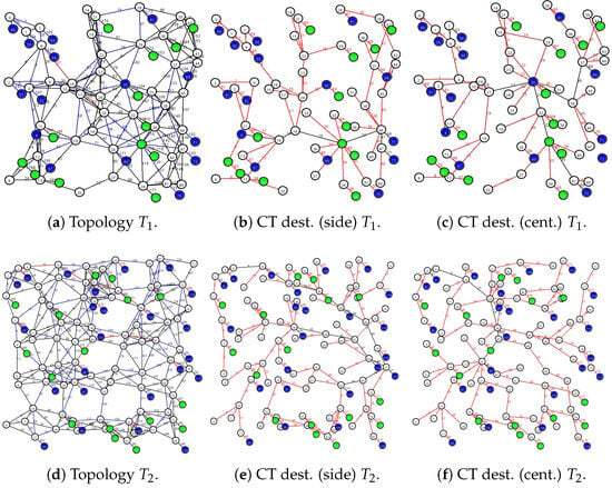
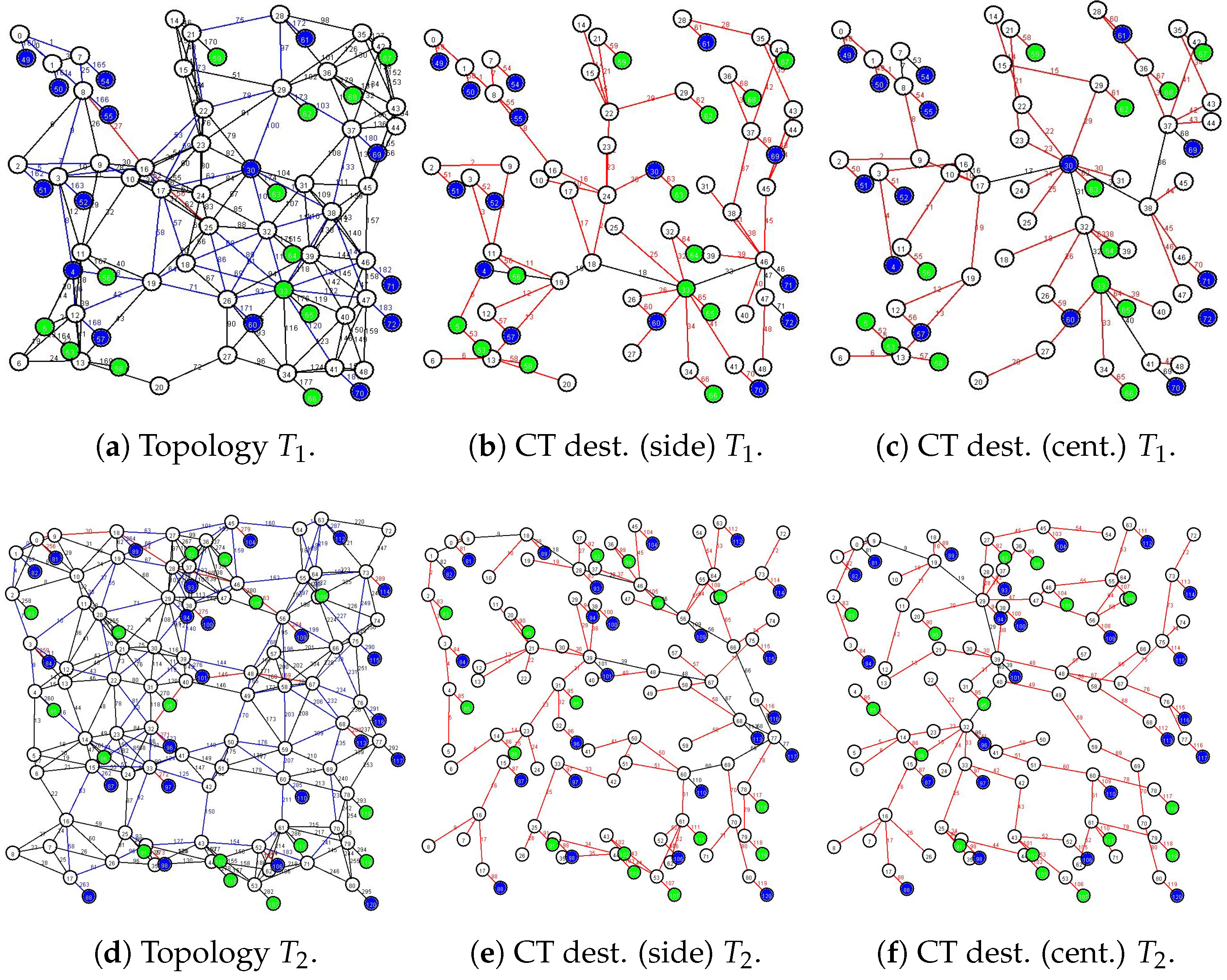
Figure 6.
CTs generated over a random network topology for multiple destinations. Green nodes represent sources, while blue nodes indicate destinations. Red links show newly added rules for flow redirection. Black links correspond to existing forwarding rules already present in the network.
Table 2.
Topology Parameters.
We evaluate two metrics: the increase in rules per flow and the rise in hop count after redirection. These are measured across varying flow counts, maximum data rates, and congestion thresholds. The congestion threshold is defined as . We compare our methods against the shortest alternative path redirection strategy. Each data point in the plot represents the average result from 200 simulation runs using three different k values. The simulation is done on a computer equipped with an AMD Ryzen 5 2600 Six-Core Processor and 16 GB of RAM. The algorithm took 1.5 s on average to converge.
6.2. Simulation Result
Firstly, we observe the number of increased rules per flow by changing different parameters. As the main objective of this research is to explore the minimum rule path to avoid interruption and excessive delay due to exhaustion of fast accessible memory in SDN switches. We use the insights obtained from the experiments that we present in Section 7 and use them in our simulation to observe the benefits of using the minimum rule path. With this simulation, we observe the tradeoff between the shortest-path and the minimum rule path redirection in terms of delay and interruptions.
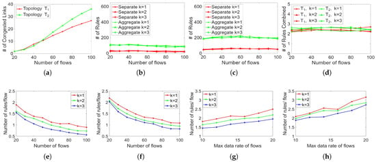
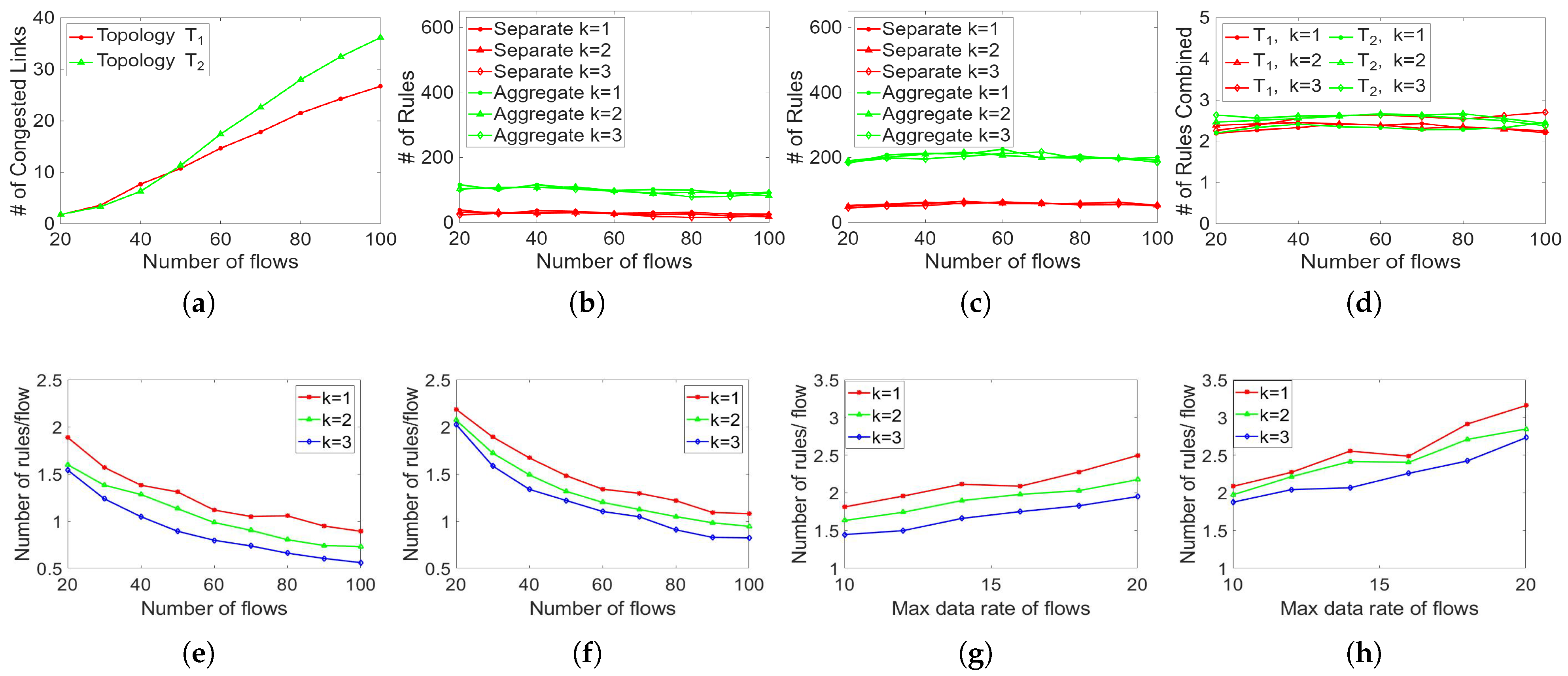
Figure 7a presents the number of congested links for different numbers of flows in and . We vary the number of flows from 20 to 100 and keep the maximum data rate as 10 Mbps. The number of congested links increases almost linearly with the number of flows. The overall number of congested links is higher in than in as is smaller than . When the number of flows is 20, the average number of congested links is nearly for both topologies. When the number of flows is 100, the average number of congested links is 36 and 26 for and , respectively. for both topologies. Since is smaller, the same amount of network traffic would make more links congested than in . The number of congested links increased linearly within this range. To observe the ratio of separate forwarding and aggregated forwarding, we record the number of both types of rules by varying the number of flows from 20 to 100 and keeping the maximum data rate as 10 Mbps. We observe that the overall number of rules remained similar after redirection, as the proposed method increases the number of rules by a little. We also observe that aggregated forwarding is used more than separate forwarding in all comparable scenarios. Figure 7b,c shows the number of both types of rules in and , respectively. We also observe the number of rules combined in each aggregated forwarding in Figure 7d. The number of rules combined remained between 2 and 3 in both topologies for k between 1 and 3. In this simulation, we vary the number of flows from 20 to 100 and keep the maximum data rate as 10 Mbps.
Figure 7.
Number of rules per redirected flow and comparison with shortest alternative path routing. (a) Congested links in and . (b) Congested links in . (c) Congested links in . (d) Congested links in . (e) Different # of flows in . (f) Different # of flows in . (g) Different flow rate in . (h) Different flow rate in .
Figure 7e,f show the number of increased rules per flow for different numbers of flows in . We vary the number of flows from 20 to 100 and keep the maximum data rate as 10 Mbps. For all values of k, the number of rules per flow decreases with the increase of the number of flows. A higher value of k produces a lower number of rules per flow. When the number of flows is higher, the network needs a higher number of rules to forward them. As a result, the existing rules help to forward the packet through an alternative way, and we need fewer new rules. If k is higher, then the number of groups increases and the selection of flows to redirect is better. When the number of flows is 20 and (or ), the average number of needed rules to redirect a flow is (or ). The number of needed rules increased by about . We observe similar behavior in . When the number of flows is 100 and , the average number of needed rules to redirect a flow is . When , the average number of needed rules to redirect a flow is . The number of needed rules decreased by about . The number of rules decreases by about and for an increase of 80 flows when and , respectively.
Figure 7g shows the number of increased rules per flow for different maximum data rates of flows in . We vary the maximum data rate of flows from 10 to 20 Mbps and keep the number of flows as 20. For all values of k, the number of rules per flow increases with the increase in maximum data rate. Similar to the previous simulation, a higher value of k produces a lower number of rules per flow. This is because when the max data rate is higher, the network observes more congested links. Because of a higher number of congested or soon-to-be-congested links, there are fewer options for redirecting a flow. As a result, a higher number of new rules is needed to forward the flow. When the maximum data rate is 10 and (or ), the average number of needed rules to redirect a flow is (or ). The number of needed rules decreased by about . When the maximum data rate is 20 and , the average number of needed rules to redirect a flow is . When , the average number of needed rules to redirect a flow is . The number of needed rules decreased by about . The number of rules increased by about and for an increase of 10 Mbps maximum data rate when and , respectively. Figure 7h plots the number of increased rules per flow for different maximum data rate of flows in . We keep the same parameters as the previous simulation and observe a similar behavior. The overall number of rules /flow is higher in than in . When the maximum data rate is 10 and , the average number of needed rules to redirect a flow is . When , the average number of needed rules to redirect a flow is . The number of needed rules decreased by about . When the maximum data rate is 20 and , the average number of needed rules to redirect a flow is . When , the average number of needed rules to redirect a flow is . The number of needed rules decreased by about . The number of rules increased by about and for an increase of 10 Mbps maximum data rate when and , respectively.
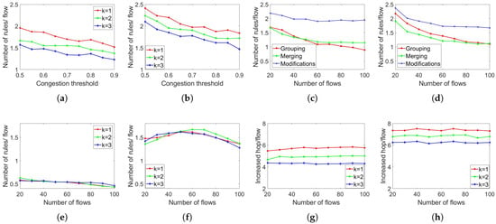
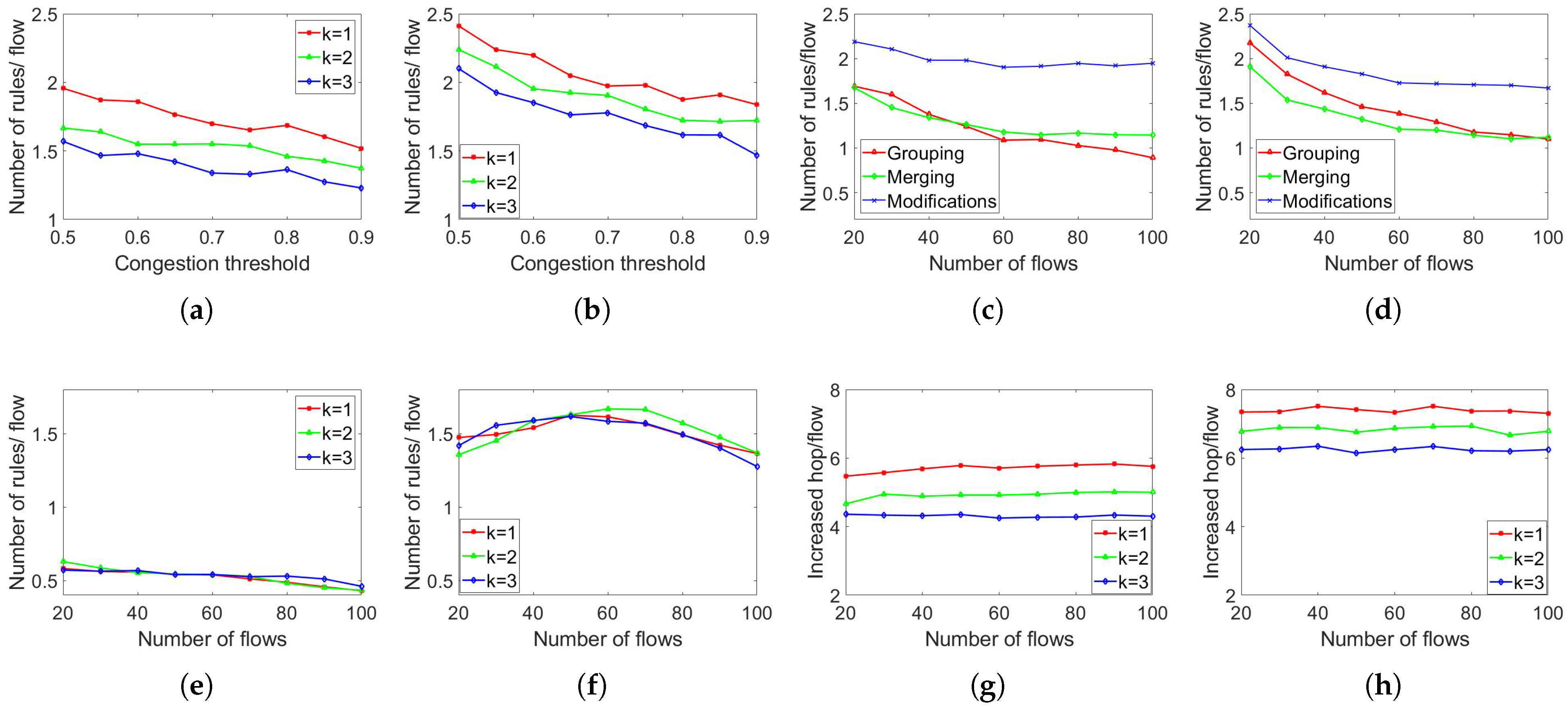
In Figure 8a,b, we show the number of increased rules per flow for different congestion thresholds of links in and . We vary the congestion threshold of links from to and keep the number of flows at 20. For all values of k, the number of rules per flow decreases with the increase in the congestion threshold of links. This is because when the congestion threshold is higher, the network observes fewer congested links. A highly utilized link is not considered congested because of the high congested threshold. Because of the lower number of congested or soon-to-be-congested links, there are more options for redirecting a flow. As a result, the number of rules needed to forward the flow is smaller. Similar to all previous simulations, a higher value of k produces a lower number of rules per flow. When the congestion threshold is and , the average number of needed rules to redirect a flow is . When , the average number of needed rules to redirect a flow is . The number of needed rules decreased by about . We observe similar behavior in .
Figure 8.
Number of rules per redirected flow and comparison with shortest alternative path routing. (a) Threshold in . (b) Different threshold in . (c) Grouping vs. Merging in . (d) Grouping vs. Merging in . (e) Difference in #rules/flow in . (f) Difference in #rules/flow in . (g) Difference in hops in . (h) Difference in hops in
Figure 8c,d show the comparison between the grouping and merging-based approaches in and . We vary the number of flows from 20 to 100, keep the maximum data rate as 10 Mbps, and set . We observe that the merging-based approach needs a smaller number of rules but a higher number of modifications than the grouping-based approach. When the number of flows is 20 in , the average number of needed rules to redirect a flow by grouping and merging based approaches is and . The number of modifications needed in the merging-based approach is per flow. The merging-based approach needs fewer (or more) rules when the number of flows is less (higher) than 50. The number of modifications for merging is always higher than the grouping-based approach. We observe similar behavior for . Therefore, when we need to save storage on an SDN switch, we need to use the merging-based approach. When we prioritize interruption over SDN storage, we need to use the grouping-based approach.
Figure 8 compares the alternate shortest path routing with redirection with k groups in terms of the number of increased hops/flow and number of increased rules per flow. For these simulations, we vary the number of flows from 20 to 100 and keep the maximum data rate as 10 Mbps. Figure 8e–h are executed with these settings. Figure 8e shows the number of increased rules per flow for different numbers of flows in . When the number of flows is 20 and , the average number of needed rules to redirect a flow in our approach is less than the shortest alternate path approach. When and , the average number of needed rules to redirect a flow in the shortest alternate path approach is and higher than our approach, respectively. The difference is similar for all k values. The difference slightly decreases with the increase in the number of flows. In Figure 8f, we present the number of increased rules per flow for different numbers of flows in . When the number of flows is 20 and , the average number of needed rules to redirect a flow in our approach is less than the shortest alternate path approach. When and , the average number of needed rules to redirect a flow in our approach is and higher than the shortest alternate path approach. The difference is also similar for all k values. The difference slightly increases and then decreases with the increase in the number of flows.
Figure 8g shows the number of increased hops/flow for different numbers of flows in . When the number of flows is 20 and , the average number of increased hops after redirecting a flow in our approach is higher than the shortest alternate path approach. When and , the average number of needed rules to redirect a flow in our approach is and higher than the shortest alternate path approach, respectively. The difference remains unchanged for all numbers of flows. Figure 8h lists the number of increased hops/flow for different numbers of flows in . We observe similar behavior as in . When the number of flows is 20 and , the average number of increased hops after redirecting a flow in our approach is higher than the shortest alternate path approach. When and , the average number of needed rules to redirect a flow in our approach is and higher than the shortest alternate path approach. The difference remains almost constant for all numbers of flows.
Therefore, based on the simulation result, we can conclude that our redirection approach with k links grouping can redirect by adding a lower number of rules than the shortest alternate path approach. The selection of the best k is not a simple one-size-fits-all way. Rather, it depends on the size and pattern of the traffic. However, in general, high k would produce more groups, more computation would be needed, but the number of rules would also be reduced. We have also observed that the number of increased hops/flow does not increase much with the increase in flows. However, the number of rules/flows decreases with the increased number of flows. Additionally, large topologies encounter a higher increment in hops and rules. Therefore, a traffic-heavy network can get the most out of the proposed approach.
7. Experiments in Datacenter
In this section, we present the details of our experimental framework, the experimental parameters, and the outcomes of our experiments.
7.1. Experimental Settings
To assess the impact of routing changes, we conduct experiments in a small-scale SDN datacenter. The setup includes fifteen SDN switches, all of which are Pica8 (P-3297) devices labeled as nodes 2 through 16 in Figure 9d. We deliberately exclude traditional routers from the topology, as they contribute to increased hop counts without influencing rule dynamics, which is our primary focus. Figure 9d illustrates a partial view of the datacenter topology. Each link is annotated with the port numbers where it is plugged. Four servers, numbered 101 to 104, are attached to leaf-level switches and serve as endpoints for traffic flows. We generate three flows: and continuously monitor to measure round-trip delays. Initially, all flows followed the shortest path. At a specific point, we introduce new rules to alter the routing paths. We then compare the delays before the change, during the transition, and after the new routes are established.
Figure 9.
Effects on ping delay (in ms). (a) Three rules added. (b) Five rules added. (c) Seven rules added. (d) Partial datacenter topology.
We use ONOS version 2.2.2 as the SDN controller in our setup. Rule management, both addition and deletion, is handled through the controller’s REST API interface. Then the controller communicates to the switch using the OpenFlow protocol [21]. To automate this process, we developed another Java application (rule modifier). It can run on a different machine than the controller, as communication is entirely API-based.
We also built a custom flow generator to send continuous ping requests to the destination. It records the round-trip delay for each packet. The default Linux ping tool introduces a pause between requests. This delay limits recording precision changes in latency. To capture delay variations with finer granularity, we needed a tool that avoids this pause and provides more frequent measurements.
The rule modifier starts by deleting all previously added rules through the REST API. Then it installs rules that direct the flow (generated by our flow generator) along the shortest path. These rules are assigned a priority of 4000. Table 3 lists both the shortest path and alternate path rules for the flow from server 101 to server 103. After 15 s, the program adds the alternate path rules with a higher priority of 5000. As a result, the flow starts to pass through the alternate path. We monitor the changes in round-trip delay during the transition. Figure 9 shows the recorded ping delays across all three experimental runs.
Table 3.
Shortest and alternative path rules.
7.2. Experimental Results
Figure 9a shows the ping delay of 40 times for flow servers 101 to 102. The flow during time 1 to 16 follows the shortest path , and the average ping delay is 0.84 ms. After changing the rules by the rule modifier program, the flow travels the alternative path . The flow during times 17 to 40 follows the alternative path, and the average ping delay is 0.93 ms. The ping delay increases by 0.09 ms for an increase of 1 hop. No other changes are observed for the addition of three new rules.
Figure 9b depicts the ping delay of 40 times of flow from 101 to 103. The flow during times 1 to 14 follows the shortest path and the average ping delay is 0.94 ms. After changing the rules, the flow travels the alternative path . The flow during times 15 to 40 follows the alternative path. During time 15 to 23 we observe a lift in delay. This lift in delay occurs because of the addition of 5 new rules. The average ping delay becomes stable during times 24 to 40 and the average delay is 1.11 ms. The delay increases by 0.17 ms for an increment of 3 hops.
Figure 9c presents the ping delay of 40 times for flow servers 101 to 104. The flow during times 1 to 19 follows the shortest path and the average ping delay is 0.87 ms. After changing the rules by the rule modifier program, the flow travels the alternative path . The flow during times 20 to 40 follows the alternative path. At time 20, the destination remained unreachable for 1 s. During times 21 to 22, we observe a high lift in delay. This lift in delay occurs because of the addition of 7 new rules. The average ping delay becomes stable during times 22 to 40, and the average delay is 1.38 ms. The ping delay increases by 0.51 ms for an increase of 5 hops.
In this small-scale experiment, we observe the behavior of the switches during rule changes. The number of rule changes between 3 and 7 shows almost no interruption to a packet drop scenario. A higher number of rule changes only causes interruption for a long period. Therefore, we can conclude that the more the change in the number of rules, the more interruptions in the flow. Changes in up to 5 rules might not cause noticeable interruption to delay-sensitive applications. Changes in 7 or more rules might cause an interruption to delay sensitive applications. The acceptable number of rule changes depends on the application. However, for any application, changes of a maximum of 3 rules are unnoticeable.
8. Conclusions
Link flooding attacks (LFAs) and link congestion are common problems in datacenter networks. Many existing solutions focus on rerouting traffic to ease congestion. However, they often overlook the rule-related limitations of SDN switches. As these switches have limited fast-accessible memory for storing forwarding rules, an excessive number of rules and updates to rules can degrade performance. Also, a high number of rules can significantly affect transmission delay. When an SDN switch stores more rules than its fast-access memory can handle, delays rise sharply. Using a modern switch, a one-hop increase in path introduces 5 to 50 s. Therefore, an exhaused fast-accessible SDN switch delay (1 ms) would be equivalent to 20 to 200 increments of hops. Updating rules across many switches also takes time, which can interrupt active flows. We address this issue in the context of LFA and congestion. Our strategy involves redirecting selected flows while keeping the number of new rules low. To achieve this, we propose and test a set of approaches based on flow grouping and merging techniques. Simulation results show that our methods reduce the number of added rules. This is sometimes done by allowing slightly longer paths, which helps balance rule overhead and routing efficiency. Using the proposed approach, the average number of increased hops is 5, which would induce a maximum delay of 250 s. On the other hand, the increased number of rules/flow is a maximum of 2. Our experiments show that any changes to up to 3 rules would not cause an interruption in the flow.
Author Contributions
Conceptualization, R.B. and J.W.; methodology, R.B., Y.C. and M.R.; software, R.B. and Y.C.; validation, R.B. and J.W.; formal analysis, R.B. and Y.C.; investigation, R.B. and Y.C.; resources, R.B. and Y.C.; data curation, R.B. and Y.C.; writing—original draft preparation, Y.C. and R.B; writing—review and editing, R.B., J.W., Y.C. and M.R.; visualization, R.B. and Y.C.; supervision, R.B. and Y.C.; project administration, R.B. and Y.C.; funding acquisition, Y.Y. All authors have read and agreed to the published version of the manuscript.
Funding
This research was supported in part by NSF grants CNS 2107014, CNS 2128378, CNS 1824440, CNS 1757533, CNS 1828363, CNS 1629746, and CNS 1651947.
Data Availability Statement
The original contributions presented in this study are included in the article. For further inquiries, please contact the corresponding author.
Conflicts of Interest
Author Yang Chen was employed by the company Meta. The remaining authors declare that the research was conducted in the absence of any commercial or financial relationships that could be construed as a potential conflict of interest.
Correction Statement
This article has been republished with a minor correction to the Author Contributions. This change does not affect the scientific content of the article.
References
- Biswas, R.; Wu, J.; Chang, W.; Ostovari, P. Optimal filter assignment policy against transit-link distributed denial-of-service attack. In Proceedings of the Global Communications Conference, Big Island, HI, USA, 9–13 December 2019. [Google Scholar]
- Afolalu, O.; Tsoeu, M.S. Enterprise networking optimization: A review of challenges, solutions, and technological interventions. Future Internet 2025, 17, 133. [Google Scholar] [CrossRef] [Scilit]
- Biswas, R.; Wu, J. Minimizing the Number of Rules to Mitigate Link Congestion in SDN-based Datacenters. In Proceedings of the 2021 IEEE International Conference on Networking, Architecture and Storage (NAS), Riverside, CA, USA, 24–26 October 2021; pp. 1–8. [Google Scholar] [CrossRef] [Scilit]
- Wu, J. Adaptive fault-tolerant routing in cube-based multicomputers using safety vectors. IEEE Trans. Parallel Distrib. Syst. 1998, 9, 321–334. [Google Scholar]
- Wang, J.; Paschalidis, I.C. Statistical Traffic Anomaly Detection in Time-Varying Communication Networks. IEEE Trans. Control Netw. Syst. 2015, 2, 100–111. [Google Scholar] [CrossRef] [Scilit]
- Andersen, D.; Balakrishnan, H.; Kaashoek, F.; Morris, R. Resilient Overlay Networks. In Proceedings of the Eighteenth ACM Symposium on Operating Systems Principles, New York, NY, USA, 21–24 October 2001. [Google Scholar]
- Argyraki, K.; Cheriton, D.R. Loose Source Routing As a Mechanism for Traffic Policies. In Proceedings of the ACM SIGCOMM Workshop on Future Directions in Network Architecture, New York, NY, USA, 30 August 2004. [Google Scholar]
- Motiwala, M.; Elmore, M.; Feamster, N.; Vempala, S. Path Splicing. In Proceedings of the ACM Special Interest Group on Data Communication, New York, NY, USA, 17–22 August 2008; Volume 38. [Google Scholar]
- Chuang, C.; Yu, Y.; Pang, A.; Chen, G. Minimization of TCAM Usage for SDN Scalability in Wireless Data Centers. In Proceedings of the Global Communications Conference, Washington, DC, USA, 4–8 December 2016; pp. 1–7. [Google Scholar]
- Chu, C.; Xi, K.; Luo, M.; Chao, H.J. Congestion-aware single link failure recovery in hybrid SDN networks. In Proceedings of the Conference on Computer Communications, Hong Kong, China, 26 April–1 May 2015; pp. 1086–1094. [Google Scholar]
- Petrov, I.S. Algorithm for reducing the number of forwarding rules created by SDN applications. Model. Anal. Inform. Sist. 2019, 26, 122–133. [Google Scholar] [CrossRef] [Scilit]
- Dridi, L.; Zhani, M.F. SDN-Guard: DoS Attacks Mitigation in SDN Networks. In Proceedings of the 5th International Conference on Cloud Networking, Pisa, Italy, 3–5 October 2016. [Google Scholar]
- Li, Z.; Hu, Y. PASR: An Efficient Flow Forwarding Scheme Based on Segment Routing in Software-Defined Networking. IEEE Access 2020, 8, 10907–10914. [Google Scholar] [CrossRef] [Scilit]
- Kamboj, P.; Pal, S. QoS-Aware Flow Routing with Minimizing Active Links and Rule Capacity Constraints in SDN Networks. In Proceedings of the 2024 22nd International Symposium on Network Computing and Applications (NCA), Bertinoro, Italy, 24–26 October 2024; pp. 211–218. [Google Scholar] [CrossRef] [Scilit]
- Um, D.; Park, H.S.; Ryu, H.; Park, K.J. Predictive Forwarding Rule Caching for Latency Reduction in Dynamic SDN. Sensors 2025, 25, 155. [Google Scholar] [CrossRef] [Scilit] [PubMed]
- Cheng, S.; Jin, D.; Ma, Y.; Chen, S.; He, H.; Yang, J. LinkGuard: Link Flooding Attack Detection and Mitigation via Spatio-Temporal Graph Convolutional Network. IEEE Trans. Netw. Sci. Eng. 2024, 11, 4059–4075. [Google Scholar] [CrossRef] [Scilit]
- Wang, J.; Fei, J.; Zhu, Y.; Wang, X.; Lin, X. Link Flooding Attack Mitigation Method Based on SDN Service Priority. In Proceedings of the 2025 4th International Conference on Intelligent Systems, Communications and Computer Networks, Nanjing, China, 21–23 February 2025; ISCCN ’25. pp. 234–245. [Google Scholar] [CrossRef] [Scilit]
- Sun, M.; Shao, K.; Wang, L. Minimizing Flow Rules for Rerouting Multi-Flows in Multi-Failure Recovery over SDN. In Proceedings of the 8th International Conference on Software and Computer Applications, Penang, Malaysia, 19–21 February 2019; Association for Computing Machinery: New York, NY, USA, 2019; pp. 555–559. [Google Scholar]
- Kotachi, S.; Sato, T.; Shinkuma, R.; Oki, E. Multicast Routing Model to Minimize Number of Flow Entries in Software-Defined Network. In Proceedings of the 20th Asia-Pacific Network Operations and Management Symposium, Matsue, Japan, 18–20 September 2019. [Google Scholar]
- Zhao, Z.; Yang, W.; Wu, B. Flow aggregation through dynamic routing overlaps in software defined networks. Comput. Netw. 2020, 176, 107293. [Google Scholar] [CrossRef] [Scilit]
- Riggs, H.; Khalid, A.; Sarwat, A.I. An Overview of SDN Issues—A Case Study and Performance Evaluation of a Secure OpenFlow Protocol Implementation. Electronics 2025, 14, 3244. [Google Scholar] [CrossRef] [Scilit]





Disclaimer/Publisher’s Note: The statements, opinions and data contained in all publications are solely those of the individual author(s) and contributor(s) and not of MDPI and/or the editor(s). MDPI and/or the editor(s) disclaim responsibility for any injury to people or property resulting from any ideas, methods, instructions or products referred to in the content. |
© 2026 by the authors. Licensee MDPI, Basel, Switzerland. This article is an open access article distributed under the terms and conditions of the Creative Commons Attribution (CC BY) license.