


Abstract
This study presents an integrated computational–experimental approach to enhance the tensile fatigue life of laser powder bed fusion (LPBF)-fabricated Ti-6Al-4V Gyroid scaffolds for orthopedic implants. Scaffolds with 60–80% porosity were designed, and finite element analysis (FEA) was employed to analyze localized stress distribution, mechanical behavior, and crack initiation sites under compression, bending, and tensile loading. The FEA results showed that elastic modulus (2.6–8.0 GPa) and compressive yield strength (85.5–251.3 MPa) aligned with human bone requirements. The bending and tensile FEA identified that tensile stress concentrations at exterior node surfaces promoted crack initiation. The LPBF-induced surface roughness further intensified these stresses, accelerating crack nucleation and compromising fatigue life. To address this, plasma electrolytic polishing (PEP) was applied at 240 V for 15, 20, and 25 min on the LPBF Ti-6Al-4V solid tensile specimens and Gyroid scaffolds. To evaluate the effect of PEP on surface integrity and fatigue performance, roughness and tensile fatigue tests were performed on LPBF Ti-6Al-4V solid tensile specimens rather than on porous scaffolds. The PEP for 20 min significantly reduced the average roughness (Ra) from 17.85 ± 1.27 µm (as-built) to 2.84 ± 0.45 µm, with an improvement of 84.10%, while also showing the smooth quality of the Gyroid scaffolds. Consequently, the enhanced surface quality led to a 30.46% increase in the average tensile fatigue cycles to failure (Nf) (σmax = 800 MPa and R = 0.1) of the solid specimens compared to the as-built condition. This improvement indicates the PEP’s effectiveness in enhancing the material fatigue life through surface defect elimination, serving as surface- and material-level supporting evidence for the potential fatigue life improvement of PEP-treated Gyroid scaffolds.
1. Introduction
The human skeleton has a unique capability for regeneration, but it cannot heal defects beyond a critical size caused by trauma, disease, and congenital conditions. These defects need an external implantable scaffold [1,2]. The proportion of patients requiring artificial implants, such as hip joint, craniofacial, maxillofacial, and dental implants, and surgical implants to replace damaged tissue, has increased in recent years [3]. An effective implant needs to offer structural support and facilitate biological healing at the bone interface, providing biomechanical compatibility for sustainable bone–implant integration, bone regeneration, and prolonged recovery [4,5].
Titanium and its alloys, specifically Ti-6Al-4V, have been extensively used as biomaterials due to their exceptional mechanical and biological properties, including a high strength-to-weight ratio, superior corrosion resistance, and biocompatibility [3,6,7,8]. Consequently, these alloys are commonly utilized for orthopedic implants and bone substitution [9,10]. However, the elastic modulus of dense Ti-6Al-4V (110 GPa) is considerably higher than that of both human cortical bone (3–30 GPa) and cancellous bone (0.2–2 GPa) [1,11,12]. This variation in elastic modulus results in considerable stress shielding, leading to an uneven stress distribution between the implant and bone, which further induces bone resorption and fracture, ultimately compromising the implant’s long-term stability and durability [11,13,14].
Recently, considerable attention has been directed toward porous titanium scaffolds due to their suitable elastic modulus and mechanical strength [15,16]. In comparison to dense titanium, porous titanium implants exhibit a lower elastic modulus, which can mitigate the stress-shielding effect associated with bone implants [17,18]. Specifically, the interconnected porous network considerably increases the implant’s surface area and facilitates cell adhesion and proliferation while simultaneously enhancing oxygen transportation and nutrient delivery, hence collectively promoting bone regeneration [13,19]. A porosity of 60–80% and a pore size of 500–1500 μm are ideal for scaffolds in bone tissue engineering, which support cell proliferation, nutrient diffusion, vascularisation, and tissue ingrowth while maintaining structural integrity [20,21].
According to the structural design of porous implants, the extensively used designs are truss structures [22], bio-inspired Voronoi structures [23], and triply periodic minimal surfaces (TPMSs) [24]. TPMS structures outperform conventional porous designs through smooth, continuous surfaces that eliminate stress concentrations, enhance permeability, mimic trabecular bone architecture, and provide a high surface area for cell adhesion and osseointegration [25,26,27]. One major challenge is the precise fabrication of these intricate porous structures. Consequently, laser powder bed fusion (LPBF) is recognized as a prominent additive manufacturing (AM) technique and is increasingly employed for the precise fabrication of such complex geometries, and has thus become a major focus of research in this field [28,29,30]. In addition, LPBF-fabricated implants demonstrate superior corrosion resistance performance compared to conventional wrought Ti-6Al-4V counterparts under simulated inflammatory conditions [31].
A main challenge of additively manufactured porous scaffolds is their reduced fatigue life compared to dense metals, resulting in bone fractures from low-magnitude, cyclic loads. Therefore, improving porous metallic scaffolds’ fatigue performance is essential to their longevity and stable integration with bone tissue [32]. Existing research on porous metals has primarily focused on compressive loads in the hip and spine joints. However, these structures are also affected by complex stress states and localized tensile stresses from bending of struts, potentially leading to structural failure. Furthermore, a high micro-scale roughness is typically exhibited by additively manufactured porous scaffolds, which produces stress concentration zones that can lead to localized microplastic deformation under cyclic loading, facilitating microcrack nucleation and ultimately resulting in fatigue failure [33,34].
Consequently, reduction in surface roughness through surface treatment processes is important to ensure the prolonged fatigue life of titanium porous structures [35]. Conventional post-treatment techniques for porous scaffolds, such as sandblasting and electrochemical polishing, face limitations due to environmental hazards; sandblasting generates harmful dust, while electrochemical polishing uses toxic acids, causing major safety and ecological challenges [36,37]. Therefore, plasma electrolytic polishing (PEP) is an effective post-processing method that can reduce the surface roughness of intricate porous structures and utilizes neutral/aqueous salt-based electrolytes without any harmful effects or environmental pollution [37,38]. PEP is especially well-suited for finishing biomedical components that feature free-form surfaces or intricate geometries. It serves both as a final processing step for such parts and as a preparatory treatment before thermal spraying [39].
Currently, the PEP technique has been successfully used to enhance the surface properties of various metallic alloys, including stainless steel [40], aluminum [41], CoCr [42], and titanium [43]. Smyslova et al. [44] investigated the influence of varying PEP durations on surface quality and rate of material removal in both conventional and ultrafine-grained Ti-6Al-4V. Kristina Navickaitė et al. [45] demonstrated that PEP can reduce the surface roughness of additively manufactured Ti-6Al-4V by up to 96.7% and increase its fatigue life by a factor of 2.4 compared to the as-built specimen. Lin et al. [46] studied that using PEP on porous titanium can lower surface roughness from Ra = 126.9 µm to 56.28 µm and trabecular structure roughness from Ra = 42.61 µm to 26.25 µm, while also eliminating surface defects, leading to enhanced surface quality.
While Ti-6Al-4V Gyroid scaffolds are widely studied for compressive fatigue, they often face bending and axial tensile loads that induce critical localized tensile stress concentrations, being prone to crack initiation under cyclic loading. The LPBF-induced surface roughness further intensifies these stress concentrations, thereby accelerating microcrack nucleation and leading to premature fatigue failure. This study aims to enhance the tensile fatigue life of LPBF Ti-6Al-4V Gyroid scaffolds by mitigating the surface defects through PEP treatment. Firstly, the Gyroid-based scaffolds with 60–80% porosity were designed, and FEA was used to analyze the stress distribution, mechanical properties, and crack initiation sites under compression, three-point bending, and tensile loading. Secondly, the PEP was applied at 240 V, with processing times of 15, 20, and 25 min to enhance the surface quality of the LPBF Ti-6Al-4V solid tensile specimens and Gyroid scaffolds. Finally, the PEP’s effectiveness on the surface improvement and tensile fatigue life of LPBF-fabricated Ti-6Al-4V material was evaluated through roughness measurement and tensile fatigue testing on LPBF Ti-6Al-4V solid tensile specimens rather than on porous scaffolds. The improved surface quality and fatigue life of dense specimens serve as fundamental surface- and material-level supporting evidence, demonstrating PEP’s capability in alleviating surface stress concentrations and providing insights for the surface integrity and tensile fatigue life enhancement of LPBF Ti-6Al-4V Gyroid scaffolds.
2. Materials and Methodology
2.1. Design of Gyroid-Based Porous Structures
Gyroid-based porous structures were modeled using 3D modeling software (nTopology, 5.9.2, New York, NY, USA), as illustrated in Figure 1. The scaffold structures were generated from the TPMS Gyroid function, defined by the implicit Equation (1):
where L (mm) is the cell size and t is a threshold parameter controlling the relative density. The wall thickness was maintained constant at 350 µm, and the Gyroid structures’ porosities of 60%, 65%, 70%, 75%, and 80% were systematically controlled by regulating the cell size (L), so the structures were designed under combined geometry/relative-density variations. As provided in Table 1, the pore size range of the designed structures is approximately 610 µm to 1460 µm, suitable for cell proliferation, nutrient diffusion, vascularisation, and tissue ingrowth [20,21]. The porosity and surface area-to-volume ratio (SA/VR) for each design were calculated directly using the following Equations (2) and (3), respectively:
where P represents the porosity, Vp denotes the volume of the porous unit structure, and V is the total volume of the porous unit structural area. corresponds to the surface area-to-volume ratio of the porous unit structure (mm−1), As is the total surface area (mm2), and Vm is the volume of the solid material of the porous unit structure. The complete geometric design parameters based on combined geometry/relative-density variations, including cell size, wall thickness, pore size, and (SA/VR) for Gyroid’s 60–80% scaffolds, are summarized in Table 1.
Figure 1.
CAD design of Gyroid unit structures: (a) Gyroid structure for compression analysis; (b) Gyroid structure for three-point bending analysis; (c) Gyroid structure for tensile analysis.
Table 1.
Design parameters of Gyroid scaffolds under combined geometry/relative-density variations.
For the compression analysis, cylindrical specimens with a diameter of 10 mm and a height of 13 mm were modeled, as illustrated in Figure 1a. For three-point bending, a rectangular cross-section measuring 10 mm in width and height, with a span length of 40 mm, was designed, as shown in Figure 1b. The tensile specimen was designed with a 20 mm gauge length and a diameter of 10 mm (2:1 length-to-diameter ratio), as demonstrated in Figure 1c. The models were filled with the Gyroid structure (60–80% porosity) throughout their compressive/tensile gauge volumes to isolate the mechanical response.
2.2. Development of FEA-Based Numerical Simulations
2.2.1. Finite Element Modeling and Boundary Conditions
Finite element simulations of compression, three-point bending, and tension were accomplished using Abaqus/Explicit 2020 (Dassault Systèmes, SIMULIA, Vélizy-Villacoublay, France) to evaluate the effects of Gyroid scaffolds with different porosities on stress distribution, load-bearing capacity, and deformation behavior. The PC setup parameters are listed in Table S1. The models were meshed in 3-matic 11.0 (Materialise NV, Leuven, Belgium) using C3D4 elements with a uniform size of 0.2 mm. Adaptive meshing refinement was applied to improve the mesh density in the high-curvature regions. Current discretization was used to observe overall deformation trends and relative stress concentration zones under different loading conditions. After meshing, the models were exported as INP files for FEA. To ensure uniform load distribution during compression, the Gyroid specimens were placed between rigid plates, as shown in Figure 2a. An axial downward displacement of 1 mm was then applied along the z-axis at a constant strain rate of 0.1 s−1 to simulate the compressive loading. As demonstrated in Figure 2b, in the three-point bending simulation, the scaffold was placed on two semicircular supports, with a load indenter of equal radius (3 mm). To implement sliding between the load indenter and the structure’s plates, tangential behavior with a friction penalty coefficient of 0.2 and surface contact was used. The load was applied by displacing a coupled reference point RP on the loader by 1.5 mm in the negative z-direction. For the tensile FEA, as illustrated in Figure 2c, the bottom grip section was fully constrained. The top section was connected to a reference point RP at its center, which was restricted to uniaxial motion. A vertical upward displacement of 2.5 mm along the z-axis was applied to the RP. Ti-6Al-4V material properties were applied to the models, including a density of 4.41 g/cm3, elastic modulus of 110 GPa, and Poisson’s ratio of 0.35.
Figure 2.
(a) Boundary conditions for compression FEA; (b) boundary conditions for three-point bending; (c) boundary conditions for tensile FEA; (d) CAD model and LPBF-fabricated Ti-6Al-4V axial tensile fatigue specimen.
2.2.2. Implementation of the Johnson–Cook Constitutive and Damage Model
The Johnson–Cook (JC) plastic and damage model was implemented; it is widely used for simulating a material’s fracture, particularly for Ti-6Al-4V, and accounts for the effects of stress triaxiality, strain rate, and temperature through experimentally derived parameters [47,48].
The equivalent flow stress (σeq) is given by:
where A, B, and C are the material constants; n and m represent the strain-hardening and temperature exponents, respectively. indicates the equivalent plastic strain, and is the dimensionless strain rate, where is the equivalent plastic strain rate and denotes the reference strain rate of 0.1 s−1; Tr is the reference temperature (298 K); and Tm is the material’s melting temperature. The material constants used in the JC model are provided in Table 2. During the quasi-static loading condition ( 0.1 s−1 at 298 K), the dimensionless strain rate = 1.0) yields a zero logarithmic term (ln(1.0) = 0), causing both the strain rate enhancement and thermal softening factor to reduce to unity (1.0). While the complete Johnson–Cook formulation is maintained within the finite element definitions in Abaqus, damage initiation under these quasi-static and isothermal conditions is governed strictly by stress triaxiality (.
Table 2.
The material constants for the Johnson–Cook strengthening model [47].
The damage initiation is governed by a dimensionless state variable, ω, bounded within the interval 0 ≤ ω ≤ 1. The condition ω = 1 defines the damage initiation. The evolution of ω is described by a monotonic function of the accumulated equivalent plastic strain, expressed as Equation (5).
where represents the incremental equivalent plastic strain and denotes the fracture strain, which is defined as a function of stress state, strain rate, and temperature through the Johnson–Cook criterion Equation (6):
where = is the stress triaxiality, is the mean stress, and represents the von Mises stress. For uniaxial tensile loading, the stress triaxiality is η = 1/3, and for uniaxial compression, η = −1/3. Once = 1, progressive stiffness degradation begins, which is governed by damage evolution, defined by a scalar variable, D, in the range 0 ≤ D ≤ 1. Damage initiation corresponds to D = 0, and complete material fracture occurs when D = 1. The initial failure strain of the material is modeled using five experimental constants (D1–D5). Among these, D1, D2, and D3 account for the effect of stress triaxiality, while D4 and D5 account for the influences of equivalent plastic strain rate and temperature, respectively. The numerical values applied in the analysis are provided in Table 3. The Hillerborg displacement-based fracture energy method was used to ensure numerical accuracy and reduce mesh dependency from strain localization during post-yield damage evolution. A characteristic length L is incorporated into the failure criterion to mitigate mesh dependency, and the damage variable D evolves linearly as a function of equivalent plastic displacement . The equation for the relation between and can be expressed as detailed below.
Table 3.
Johnson–Cook experimental constants for Ti-6Al4V [47].
Before damage initiation, = 0; after damage initiation,
and at failure
where L is the characteristic element length.
In order to reduce severe element distortion and maintain a high-quality discretization throughout the simulation, adaptive mesh refinement was used. In Abaqus/Explicit, numerical element deletion was enabled. A C3D4 element’s stress contribution is set to zero, and it is removed from the active mesh domain when the scalar damage variable D reaches 1 at every integration point. This removal process effectively mimics the development and propagation of cracks and progressive strut fracture.
2.3. Experimental Setup
2.3.1. LPBF Fabrication of Gyroid Scaffolds and Tensile Specimens
The cylindrical dog-bone tensile fatigue test specimens and Gyroid scaffolds were fabricated using an LPBF machine (NCL-M2120, Chamlion Laser Technology, Nanjing, China). The LPBF fabrication was carried out with optimized process parameters: a laser power of 120 W, scanning speed of 1100 mm/s, layer thickness of 0.03 mm, and hatch spacing of 0.08 mm. The material was Ti-6Al-4V powder with a particle diameter range of 15–53 μm. The scanning electron microscope (SEM) morphology and chemical composition of the powder are provided in Supplementary Figure S1 and Table S2, respectively. The Ti-6Al-4V solid tensile specimens and Gyroid scaffolds were fabricated in a vertical direction, 90° relative to the build plate. The scanning strategy of 67° inter-layer hatch rotation was utilized to promote microstructural isotropy. Argon gas protection was used, and the oxygen content was controlled within 100 ppm to prevent oxidation. The dense LPBF-fabricated Ti-6Al-4V tensile specimens, as shown in Figure 2d, were utilized for surface roughness measurement and fatigue testing instead of porous scaffolds for the following reasons: (i) they share identical processing parameters to accurately replicate the scaffolds’ strut surfaces, (ii) they enable feasible roughness (Ra) measurement, and (iii) they enable precise fatigue analysis that is difficult to achieve with porous samples due to unpredictable stress distributions and failure sites.
2.3.2. Plasma Electrolytic Polishing (PEP) Process
The PEP process was utilized to enhance the surface quality of LPBF-fabricated Ti-6Al-4V components. The PEP experimental setup is demonstrated in Figure 3a, and physical experimentation is presented in Figure S2. The study focused on two distinct geometries: standard tensile specimens and Gyroid scaffolds with porosities of 60%, 70%, and 80%. Polishing was conducted in 4 L of aqueous electrolyte (5 wt% NH3OHCl and 0.8 wt% NaF) [38] using Ti-6Al-4V as an anode and stainless steel as a cathode. The immersion depth was fixed at 10 cm. The process temperature was maintained at 85 °C via an external heating containment bath temperature of 85 °C. At a constant voltage of 240 V, polishing times were investigated: 15, 20, and 25 min to evaluate the influence of processing duration. After PEP, all specimens were rinsed with deionized water and air-dried. Subsequent analyses were conducted to analyze the surface roughness and measure the tensile fatigue performance of the as-built and PEP-treated samples. The LPBF Ti-6Al-4V tensile solid specimens after the PEP treatment are demonstrated in Figure 3b.
Figure 3.
(a) The experimental setup for PEP; (b) PEP-treated LPBF Ti-6Al-4V solid tensile specimens, with the PEP at (240 V, time: 15 min, 20 min, 25 min).
2.3.3. Surface Characterization
Surface Roughness Measurement
A Mitutoyo Surftest SJ-210 portable surface roughness tester (Mitutoyo Corporation, Kawasaki, Japan) was utilized to determine the surface roughness (Ra) in accordance with ISO 4287:1997 [49,50]. A Gaussian filter was applied with a cutoff length (λc) of 0.8 mm and an evaluation length (ln) of 4.0 mm. The stylus tip radius was 2 µm and the measuring force was 0.75 mN. All specimens were built vertically in the LPBF build chamber; therefore, the specimen axis was parallel to the LPBF build direction. Measurements were performed with the stylus travel direction parallel to both the specimen axis and the LPBF build direction. To minimize the vibrations during experimentation, the specimen was fixed in the V-groove and secured with a clamping screw, as shown in Figure S3. Four experimental groups were evaluated: the as-built (control) group and three PEP-treated groups (PEP-15, PEP-20, and PEP-25). For each group, three independent samples were prepared; on each specimen, three measurement locations were randomly selected along the 20 mm gauge length, avoiding the shoulder transition regions (R20 mm) and any visible surface defects. A single mean (Ra) value was calculated for each particular sample by averaging the three (Ra) values acquired per sample. The overall mean (Ra) and standard deviation (SD) for each polishing condition (n = 3 samples per condition) were then computed by averaging the three sample means per condition.
Surface Morphology
To supplement the qualitative roughness data, the surface morphology of the Ti-6Al-4V Gyroid scaffolds (60%, 70%, and 80% porosity) was assessed both before (as-built) and after PEP treatment. A 5.1-megapixel industrial digital camera (Model: CP6051100A; Aptina 1/2.5″ CMOS sensor, Hangzhou, China) was used to achieve high-resolution optical imaging. This qualitative analysis was used to visually assess the elimination of partially fused powders and the refinement of the strut surfaces throughout the Gyroid scaffolds at the same PEP process parameters. Furthermore, scanning electron microscope (SEM) fractography of the fracture PEP-treated tensile specimens was conducted to analyze the fatigue source using the Hitachi S-4800 SEM (Tokyo, Japan).
2.3.4. Tensile Fatigue Testing
The uniaxial tensile fatigue testing was conducted employing cylindrical LPBF-fabricated dog-bone specimens. The specimens were designed in accordance with ASTM E466 with a length of 110 mm, a gauge section 20 mm in length and 10 mm in diameter, and grip sections 18 mm in diameter and 40 mm in length. To minimize the local stress concentration, a transition shoulder radius of 20 mm over a 5 mm axial span between the grip sections and the gauge length was designed, as shown in Figure 2d. The tensile fatigue analysis was performed on four distinct groups of Ti-6Al-4V tensile specimens: three PEP-treated groups (PEP-15, PEP-20, and PEP-25) and an as-built (control) group. Each group consisted of three independent samples. In compliance with technical requirements, all specimens were inspected to verify identification and ensure they were free of surface defects, such as cracks or corrosion. The tests were accomplished at room temperature in a controlled environment using a sinusoidal waveform with a maximum stress (σmax) of 800 MPa, stress ratio (R) of 0.1, and frequency (f) of 10 Hz. All specimens (n = 3 per group) were tested to complete fracture under continuous sinusoidal loading; no run-outs or censored observations occurred. The fatigue life for each group was recorded, and the outcomes were averaged to assess the influence of the PEP treatment durations relative to the as-built control group.
3. Results and Discussion
3.1. FEA Results
3.1.1. FEA of Stress Distribution and Deformation Under Compression
Figure 4 presents the simulated stress distribution and deformation behavior during axial compression, while Figure 5a depicts the corresponding stress–strain curve of the Ti-6Al-4V Gyroid-60%-porosity scaffold.
Figure 4.
The FEA-simulated stress distribution and fracture analysis of a Ti-6Al-4V Gyroid-60%-porosity scaffold at different strain levels under axial compression.
Figure 5.
FEA-simulated results of axial compression: (a) stress–strain curve of Ti-6Al-4V Gyroid-60% porosity; (b) stress–strain curves of Ti-6Al-4V Gyroid scaffolds with 65–80% porosity.
The FEA results identify three distinct phases during the compression of the Gyroid-60%, characterized by linear elasticity, post-yield hardening, and a plateau with layer-by-layer collapse. Initially, the Gyroid’s smooth, interconnected porous network ensures uniform stress distribution, with a linear elastic limit of 220 MPa at 2.7% strain. Upon reaching 3.4% strain, the structure achieves its 0.2% offset compressive yield strength of 251.3 MPa, marking the transition to plastic deformation. The scaffold continues to resist increasing loads until reaching its ultimate compressive strength (UCS) of 324.2 MPa at 5.89% strain, where the substantial stress concentration at cell-connecting joints and thin-walled regions triggers the first major structural collapse. Beyond this peak, the Johnson–Cook damage model predicts a sharp drop in load-bearing capability to 37.98 MPa due to complete fracture of the most heavily loaded Gyroid layers. Consequently, the overall load-bearing capacity is reduced due to the complete fracture of these heavily loaded layers. In the final phase, from 6.2% to 7.7% strain, the plateau region can be observed with a series of stress fluctuations. These peaks and valleys indicate the progressive layer-by-layer deformation of the Gyroid structure in correspondence with continuous applied compression. As a one-layer fracture occurs, the structure momentarily maintains certain strength until the subsequent layer collapses to tolerate the compressive load.
The comparison of FEA-simulated compressive stress–strain curves for Ti-6Al-4V Gyroid scaffolds with 60–80% porosity, presented in Figure 5a,b, reveals a clear inverse relationship between porosity (combined geometry/relative-density variations) and load-bearing capacity. The Gyroid-60% exhibits the highest mechanical performance due to its lower porosity, higher relative density, shorter wall spans, and lower surface area-to-volume ratio, which collectively promote uniform stress distribution and prevent localized stress concentration. As porosity increases from 65% to 80%, the cell size enlarges while wall thickness remains constant at 0.35 mm, resulting in increased wall slenderness and longer spans between junctions. Therefore, the higher-porosity scaffolds are more susceptible to deformation, localized buckling, and premature failure; hence, a notable reduction in their compressive load-bearing capability has been observed.
The FEA-simulated mechanical performance is presented in Figure 6 and summarized in Table 4. The results reveal that increasing porosity (combined geometry/relative-density variation) from 60% to 80% reduces the mechanical performance of Ti-6Al-4V Gyroid scaffolds. The elastic modulus (E) decreases from 8.0 to 2.6 GPa, compressive yield strength (σy) drops from 251.3 to 85.5 MPa, and ultimate compressive strength falls from 324.2 to 115.9 MPa. When compared to human bone properties, scaffolds with 60–75% porosity exhibit an elastic modulus (3.9–8.0 GPa) within the cortical bone range (3–30 GPa) [1]. The Gyroid-80% scaffold (2.6 GPa) aligns closely with a cancellous bone stiffness of (0.2–2 GPa) [12] and (0.1–4.5 GPa) [20]. Regarding yield strength, the 60%- and 65%-porosity scaffolds (251.3 and 198.2 MPa) exceed cortical bone requirements (20–193 MPa) [21], demonstrating superior load resistance, whereas 70–80%-porosity scaffolds fall within the cortical bone threshold, with Gyroid-80% (85.5 MPa) approaching the upper limits of cancellous bone strength (2–80 MPa).
Figure 6.
FEA-simulated mechanical properties of Ti-6Al-4V Gyroid scaffolds with 60–80% porosity: (a) elastic modulus; (b) compressive yield strength.
Table 4.
FEA-simulated compressive mechanical properties of Ti-6Al-4V Gyroid scaffolds with 60–80% porosities and natural bones’ mechanical properties [1,11,12,20].
The FEA results suggest that Ti-6Al-4V Gyroid scaffolds exhibit mechanical properties within the range typically required for load-bearing orthopedic applications, and that porosity (combined geometry/relative-density variation) can be adjusted to match host bone mechanical requirements. Furthermore, under axial compression, the Gyroid-60% scaffold exhibits a relatively uniform stress distribution, with prominent stress concentrations appearing both at external nodes and internal walls once loads exceed structural capacity, leading to progressive layer-by-layer collapse. However, scaffolds frequently encounter bending and tensile loads. Under bending, complex stress behavior arises with simultaneous compressive and tensile stress concentrations, where localized tensile stresses are particularly vulnerable to crack initiation and complete fracture. Under pure tension, stress distribution is relatively uniform, but scaffolds deform more readily under high tensile loading than under compression. Ultimately, these localized tensile stress concentrations generated during bending and axial tension compromise the fatigue life of Ti-6Al-4V Gyroid scaffolds under cyclic loading.
3.1.2. FEA of Stress Distribution Under Three-Point Bending
As presented in Figure 7, during bending of the Ti-6Al-4V Gyroid-60% scaffold, a non-uniform complex stress distribution throughout the structure is observed, leading to simultaneous localized compressive and tensile stress regions. The bending moment at the central loading point produces compressive stresses and tensile stresses on the upper concave and lower convex surfaces, respectively, as shown in Figure 7a. In particular, the localized tensile stresses are more critical for premature crack initiation in Ti-6Al-4V scaffolds and result in localized plastic deformation due to the lower fracture strain under tension compared to compression. In Figure 7b, a dominant tensile stress concentration can be observed on the lower convex surface of the scaffold. Notably, due to continuous stretching of the struts under tension, the tensile stress concentration is more pronounced at the connecting nodes’ external surfaces than at the interior walls’ surfaces. These localized stress concentrations at the exterior surface regions serve as major initiation sites for microcracks, ultimately leading to crack propagation, which causes considerable loss of structural integrity and mechanical performance under bending conditions. In contrast, compressive stresses on the top concave surface are more effectively dissipated through the porous interconnected network of the Gyroid structure; consequently, this delays catastrophic fracture, as shown in Figure 7c.
Figure 7.
FEA-simulated complex stress distribution during three-point bending of Ti-6Al-4V Gyroid-60%-porosity scaffold: (a) sectional view; (b) sectional view of lower (convex) surface; (c) isometric view of the (concave) surface.
In conclusion, the results reveal that the bending strength of Ti-6Al-4V Gyroid scaffolds is highly dependent on the localized tensile stress concentration at the external surface of connecting joints, which can lead to crack initiation and compromise the fatigue life.
3.1.3. FEA of Stress Distribution and Deformation Under Tension
An isolated tensile simulation was performed to evaluate the stress distribution under pure tension and to quantify the severity of surface stress concentrations at the exterior connecting junctions, particularly regarding their influence on crack initiation. As shown in Figure 8a,b, initially, a low average stress concentration is observed at the surface of the exterior connecting joints of the Gyroid scaffold. In contrast, the internal wall’s surface experiences even less average stress concentration. Progressively, the average stress concentration on the surfaces of the exterior connecting regions becomes more pronounced with an increase in tensile displacement relative to the stress concentrations observed on the internal wall surfaces, as illustrated in Figure 8c. When the tensile load increases beyond the structure’s maximum load-bearing capacity, microcrack nucleation occurs in the high surface stress concentration regions at the exterior connecting nodes, as shown in Figure 8d. Once the outer structural integrity is breached, the load redistributes, and tensile stresses accumulate on the internal walls, substantially increasing the load-bearing demand on the internal structure, as demonstrated in Figure 8e. As a result, rapid crack propagation through the tensile redistributed stress regions on the internal wall leads to complete catastrophic fracture of the scaffolds, as presented in Figure 8f. The tensile FEA indicates that microcracks initiate primarily at the scaffold’s exterior regions, driven by high surface stress accumulation. Exceeding a critical load intensifies these stresses, triggers crack initiation at the exterior regions, and, after the loss of peripheral mechanical integrity, cracks propagate to complete fracture of the Ti-6Al-4V Gyroid scaffold. Thus, the high stress concentration at the scaffold’s outer surface controls the tensile strength.
Figure 8.
FEA-simulated stress distribution and deformation behavior of Ti-6Al-4V Gyroid-60%-porosity scaffold under tensile loading: (a) initial stress distribution; (b) stress distribution at initial tensile loading; (c) high stress concentration at the exterior connecting node surfaces; (d) crack nucleation in high-stress regions; (e) stress redistribution at the internal walls; (f) complete fracture.
Figure 9 displays the FEA-simulated tensile stress–strain behavior of Gyroid scaffolds across 60–80% porosity. The tensile load-bearing capacity is substantially lower than the compressive response, as displayed in Figure 5, indicating the scaffold’s greater susceptibility to tensile deformation. Although a higher tensile failure strain is achieved due to stress redistribution to the internal walls, the localized surface stress concentration at the exterior connecting nodes remains critically prone to microcrack formation. Quantitative comparison with Figure 6b and Table 4 reveals substantial reductions in tensile yield strength (224.4 to 72.4 MPa) and ultimate tensile strength (314.4 to 112 MPa) relative to compression, underscoring the finding that tensile stresses are more detrimental.
Figure 9.
FEA-simulated stress–strain curves of Ti-6Al-4V Gyroid scaffolds with 60–80% porosity under tensile loading.
Overall, from bending and tensile FEA results, the tensile stress accumulation at the scaffold’s exterior connecting nodes’ surfaces makes these regions primary sites for microcrack initiation and sensitive points for plastic deformation, as presented in Figure 7 and Figure 8, respectively. Between the two loadings, bending proves more critical, as the joints on the lower convex side experience more severe peak surface tensile stress concentrations, as shown in Figure 7b, than under axial tension. Consequently, under bending conditions, these tensile-stress-concentrated joints can reach their critical fracture stress earlier than under axial tension.
The significance of tensile stress accumulation at the scaffold’s exterior surfaces is further amplified due to LPBF-induced micro-surface roughness. The numerous surface micro-notches induced during LPBF fabrication increase localized stress concentration at the external nodes and drastically lower their resistance to crack formation [51]. Consequently, during cyclic loading, these surface defects promote premature crack initiation and reduce scaffolds’ overall mechanical integrity and fatigue life [32]. Therefore, surface refinement of these critical exterior regions is essential to enhance structural integrity and tensile strength, as previous studies have demonstrated that surface finishing effectively mitigates defects and improves both tensile strength and elongation [38,52]. Consequently, PEP is an efficient surface treatment technique that is not only capable of enhancing the surface condition but also of modifying the surface morphology of LPBF-fabricated Ti-6Al-4V porous structures [38,53]. A large decrease in surface roughness (Ra) at the scaffold’s exterior regions via PEP can minimize the tensile stress concentration, which leads to a delay in crack initiation under tensile cyclic loading conditions. As a result, an increase in the tensile fatigue life of Ti-6Al-4V Gyroid scaffolds under both bending and pure tensile loading conditions can be achieved. The LPBF process further intensifies the stress concentration because surface roughness acts as micro-notches at the scaffold’s exterior high-concentration regions, as these high-stress regions are indicated by FEA, accelerating crack initiation under cyclic loading. The proposed connection between FEA-predicted stress concentrations and PEP-induced fatigue improvement is a mechanistic hypothesis based on the literature, not a direct numerical prediction, because defect-free idealized geometries were used in the FEA simulations. Future work will incorporate representative surface defects to quantify their effect on local stress fields.
3.2. Experimental Results
3.2.1. Influence of PEP on Surface Roughness Improvement
The surface roughness (Ra) experiment is presented in Figure 10a, while the influence of PEP at (240 V; processing time: 15, 20, 25 min) on the surface quality enhancement of LPBF-fabricated Ti-6Al-4V solid tensile specimens and the corresponding percentage improvement relative to as-built samples are shown in Figure 10b and summarized in Table S3. The outcomes show a substantial improvement in the surface roughness (Ra), and the results consist of three stages: an initial prominent reduction, a smooth surface condition, and surface degradation. Initially, the as-built LPBF-fabricated specimens exhibited a high average surface roughness (Ra) of 17.85 ± 1.27 µm. These surface imperfections act as numerous micro-notches, which are the critical source for stress concentration and microcrack initiation, and cause a considerable reduction in the material’s fatigue life under cyclic tensile loading [54,55]. Consequently, PEP was applied, which is an effective surface treatment process capable of enhancing the surface quality of LPBF-fabricated complex structures. The PEP process utilizes an electrolytic solution with minimal adverse effects on the environment. A thin layer of vaporized electrolyte, known as the plasma envelope, forms around the Ti-6Al-4V specimens during the process. The plasma envelope acts as a stable layer of vapor that separates the metal from the liquid electrolyte. Subsequently, the combination of localized micro-electrical discharges, electrochemical dissolution, and chemical reactions occurs within this plasma envelope, leading to the removal of surface imperfections. Initially, the high current density in the plasma envelope concentrates on the major surface irregularity peaks during the normal polishing process, which results in a notable reduction in surface roughness (Ra) [56].
Figure 10.
(a) Surface roughness measurement of LPBF-fabricated (as-built) and PEP-treated Ti-6Al-4V tensile specimens. (b) Average surface roughness with standard deviation; surface roughness of individual samples; percentage improvement (%) in PEP–treated Ti-6Al-4V specimens relative to as-built specimens; the error bars represent the standard deviation across three specimens per condition.
Throughout the Ti-6Al-4V PEP process, continuous anodic reactions cyclically form and break down a TiO2 layer on the surface. This oxide layer acts as a dielectric barrier, critically regulating the micro-discharge frequency as part of the fundamental mechanism [39,57]. The TiO2 anodic oxidation reaction is illustrated in Figure 11, and the plasma discharge behavior, TiO2 oxide layer cyclic formation, and breakdown stages during the PEP process are presented in Figure 12.
Figure 11.
Schematic demonstration of the anodic oxidation reaction of the TiO2 oxide layer formation.
Figure 12.
Schematic demonstration of plasma discharge behavior and TiO2 oxide layer formation: (a,a1) PEP-15 min, the initial reduction in surface roughness (Ra); (b,b1) PEP-20 min, smooth surface condition; (c,c1) PEP-25 min, over-polishing phase.
When the PEP is applied at a constant voltage of 240 V for 15 min, a prominent decrease in average surface roughness (Ra) is observed from 17.85 ± 1.27 µm to 5.68 ± 1.57 µm, with an improvement of 68.18% over the as-built condition, as shown in Figure 10b. In particular, at this stage, the plasma envelope’s thickness close to the surface peak regions is locally reduced, resulting in localized high current density, which targets the prominent as-built irregularities as compared to valleys. Hence, a sharp decline in surface roughness (Ra) is achieved. Despite the considerable roughness reduction, the large standard deviation of ±1.57 µm across the specimens, evident from the error bars in Figure 10b, reveals major roughness differences among samples and highlights the non-uniform surface conditions. As illustrated in Figure 12a, the PEP’s schematic demonstration for 20 min shows that, at this stage, the PEP has initiated the removal of a large percentage of rough particles; however, due to the short duration, it is unable to achieve a smooth and uniform surface across all three samples. Also, the formation of a stable plasma envelope depends on both specific processing time and surface flatness. At 15 min, the rapidly evolving surface topography causes the plasma envelope to be unstable and plasma discharges to be highly localized and aggressive at the major surface peaks and unmelted particles. As a consequence, the process removed the surface peaks but was unable to achieve the desired surface quality convergence [56], which is observed in the following 20 min PEP processing condition. Furthermore, as shown in Figure 12(a1), the role of non-uniform TiO2 anodic oxide layer formation is critical to this instability. The oxidation begins immediately upon the immersion of specimens in the electrolyte. However, in this phase, oxide layer formation continues to exist in a highly unstable state, alongside the vapor envelope, thus preventing the formation of a consistent oxide layer. Therefore, the polishing process remains non-uniform across the specimens; as a result, a major difference in surface roughness (Ra) between samples can be observed, as reflected by the large standard deviation.
When the PEP duration is increased to 20 min, the surface reaches a smooth quality among the tested conditions, with an average roughness (Ra) of 2.84 ± 0.45 µm. This increment in treatment duration makes the plasma discharges effective at removing the prominent surface imperfections produced during LPBF fabrication and allows the PEP process to reach a consistent micro-polishing phase. Consequently, a maximum surface improvement of 84.10% in comparison to the as-built condition is observed, as shown in Figure 10b. In addition, from PEP-20 min in Figure 12b, at this stage, the plasma envelope is more uniform around the specimens, as the major micro-surface irregularities have been leveled effectively, which results in uniform and consistent finishing, as observed by the lowest standard deviation of ±0.45 µm among the specimens. From the perspective of oxide layer formation, as presented in Figure 12(b1), the surface achieves sufficient smoothness that allows the formation of a homogeneous TiO2 oxide layer across the Ti-6Al-4V surface. Also, due to the achievement of a stable steady state, where the rate of oxide formation matches the rate of plasma-assisted dissolution, as presented in Figure 12(b,b1), consequently, a smooth surface is achieved. The consistent dielectric strength provided by the TiO2 oxide layer controls the micro-discharge intensity across the specimens, resulting in uniform polishing and a smooth surface, which is evident in the lowest standard deviation of surface roughness (Ra) among the three samples. This enhanced surface quality is particularly favorable for Ti-6Al-4V tensile specimens, as the reduction in surface irregularities such as microscopic notches helps to mitigate the stress concentration sites, which can lead to an improvement in the tensile fatigue life.
In contrast, when the process time increased to 25 min, the surface roughness increased to 3.53 ± 0.95 µm, and the improvement rate decreased to 80.22%, compared to the previous condition of PEP-20 min, as presented in Figure 10b. Also, the increment in standard deviation to ±0.95 µm among the specimens reflects that the surface topography is inconsistent and the treatment has approached the over-polishing stage, in which the entire process transforms from micro-smoothing to micro-damage. The same results were observed by Zou et al. [53], in which the prolonged polishing time reduced the surface roughness, while the surface quality was compromised due to over-polishing.
As discussed previously, the surface quality reached a certain level of smoothness within 20 min of PEP. Further increments in processing time make plasma discharging no longer distributed across peaks. Instead, the discharges occur more abruptly on the microscopic defects and thinner regions of the stable TiO2 oxide layer, as shown in the schematic demonstration in Figure 12c. The oxide layer cannot withstand the frequent, intense, localized, high-energy plasma discharge for a prolonged time and begins to rupture, as shown in Figure 12(c1). This breakdown allows plasma discharges to interact with the underlying bulk material, leading to localized melting/etching, material degradation, and the formation of micro-pits [56]. Consequently, the transition from controlled plasma discharge behavior toward random and destructive etching increases the surface roughness [58]. Furthermore, the uncontrolled consumption of bulk material compromises the dimensional accuracy [59], while micro-pit formations act as stress concentration sites [56]. All of these defects promote early crack initiation and propagation and can substantially reduce the fatigue life of the specimens under tensile cyclic loading. The findings show that extending the PEP duration to 25 min at 240 V reduces process effectiveness, as the mechanism shifts from micro-scale polishing to surface deterioration. Overall, 20 min of PEP treatment represents the optimum duration for simultaneously enhancing surface quality and improving the mechanical integrity of the Ti-6Al-4V tensile specimens.
3.2.2. Influence of PEP on Surface Morphology of Ti-6Al-4V Gyroid Scaffolds
The influence of PEP processing at (240 V; processing times: 15, 20, 25 min) on the surface quality of LPBF-fabricated Ti-6Al-4V Gyroid scaffolds with 60%, 70%, and 80% porosity is presented in Figure 13. The surface evolution analysis reveals the same trend as previously observed in Section 3.2.1. As illustrated in Figure 13(a,a1,a2), the as-built Gyroid scaffolds have a highly rough surface morphology with partially melted powder particles and sintered grains adhered to the strut walls. Such surface micro-roughness, inherent to the LPBF-fabrication, creates a dense network of micro-notches that act as stress concentrators, promoting localized surface stress accumulation and serving as preferential sites for crack initiation [54,55]. This is particularly detrimental for porous scaffolds under tensile cyclic loading, where fatigue performance is critical. Therefore, PEP has been applied to enhance the surface quality of LPBF-fabricated Ti-6Al-4V Gyroid scaffolds, which can substantially reduce surface micro-notches in the exterior regions, ultimately leading to an improvement in the tensile fatigue life.
Figure 13.
Macro-surface morphology evolution of Ti-6Al-4V Gyroid scaffolds with 60%, 70%, and 80% porosities: (a,a1,a2) as-built condition, high surface roughness; (b,b1,b2) PEP-15 min, initial reduction in surface roughness; (c,c1,c2) PEP-20 min, smooth surface; and (d,d1,d2) PEP-25 min, over-polishing.
When PEP is applied for 15 min, an obvious reduction in surface roughness can be observed in the Gyroid scaffolds compared to the as-built condition, as shown in Figure 13(b,b1,b2). The prominent surface asperities, such as partially melted powder grains adhering to the surface and sharp satellite particles, are removed through highly localized plasma discharges. However, both the outer and inner surfaces remain rough, with the relative difference being that the inner surface is rougher. This variance in surface quality arises because the peripheral wall surface is directly exposed to the intense electrical discharges developed through the plasma envelope. In contrast, the internal surface remains relatively rough as it is polished gradually due to insufficient electrolyte flow inside the inner porous channels and the shielding effect.
Furthermore, when PEP is applied for 20 min, the scaffold’s surfaces achieve a relatively smooth surface finish, as compared to the previous PEP-15 surface condition, exhibiting a reflective and uniformly smooth outer surface, as presented in Figure 13(c,c1,c2). These results indicate that with increased processing duration, macro-roughness is effectively reduced and the PEP process approaches a consistent micro-polishing phase due to the uniform stability of the plasma gaseous envelope, while preserving the Gyroid’s ideal structural integrity. Additionally, the extended processing time yields a slight improvement in interior roughness as compared to the PEP-15 min, signifying that partial penetration of the PEP process inside complex structures is a valuable advantage over traditional techniques. Nevertheless, a relative difference between the external and internal surfaces persists due to the limited flow of electrolytes within the Gyroid’s narrow channels.
As illustrated in Figure 13(d,d1,d2), specimens processed for 25 min exhibit a smooth surface finish; however, this is accompanied by major dimensional loss, material degradation, and a detrimental reduction in the wall thickness of the Gyroid exterior walls. This phenomenon indicates that the PEP process has transitioned from a localized leveling mechanism to a global material removal phase, commonly referred to as over-polishing. In porous structures, this transition leads to dimensional loss and prominent thinning of the structural wall [59]. Such dimensional degradation compromises the load-bearing mechanical performance and structural stiffness of scaffolds. Furthermore, the formation of localized micro-pitting diminishes surface integrity and introduces new stress concentration points [56], leading to crack initiation. These macroscopic defects are detrimental and expected to largely reduce the fatigue life of Ti-6Al-4V Gyroid scaffolds under cyclic tensile loading. Additionally, a slight difference between the exterior and interior surface roughness exists, which is consistent with observations from the 15 min and 20 min PEP durations.
Overall, these findings demonstrate that PEP is a highly effective method for removing surface irregularities, particularly on the exterior wall surfaces of LPBF-fabricated Ti-6Al-4V Gyroid scaffolds. Relative to the as-built condition, the treatment at 240 V for 20 min produced the smoothest surface quality among the parameters examined, which is also evident from Figure 13(c,c1,c2) and Section 3.2.1; Figure 10b supports this as surface-level evidence. The mitigation of stress concentration sites yields a smooth surface finish, which is expected to considerably enhance the scaffold’s tensile fatigue life and structural durability by delaying fracture initiation in high-stress regions at the exterior walls under cyclic tensile loading. To further provide macro-scale supporting evidence of the improved fatigue life of Ti-6Al-4V Gyroid scaffolds through the PEP process, the following section examines the connection between surface quality and mechanical performance via a comprehensive fatigue analysis under tensile cyclic loading.
3.2.3. Influence of PEP on the Fatigue Life Enhancement
This section compares the average tensile fatigue cycles to failure (Nf) (σmax = 800 MPa and R = 0.1) of as-built LPBF-fabricated Ti-6Al-4V tensile specimens and PEP-treated specimens processed at 240 V for durations of 15 min, 20 min, and 25 min. The average tensile fatigue cycles to failure were calculated under consistent tensile cyclic loading, utilizing n = 3 samples for each processing group. The experimental results highlight the impact of different durations of PEP on the average tensile fatigue life of Ti-6Al-4V specimens. As presented in Figure 14 and Table S4, the as-built specimens exhibited the shortest average fatigue cycles to failure (2380 ± 117 cycles). The reduced fatigue performance of as-built specimens can be attributed to the material’s extreme sensitivity to micro-notches due to the LPBF-induced high surface roughness (Ra). As presented in Section 3.2.1, in Figure 10b, the as-built specimens exhibited an average surface roughness (Ra) of 17.85 ± 1.27 µm, which occurred due to partially melted powder particles and deep inter-track valleys. The effects of these surface micro-defects on the reduced average fatigue life of as-built Ti-6Al-4V specimens can be well understood by Griffith’s strength theory modified by Irwin and Orowan [38], which defines the critical stress (σc) for crack propagation and localized stress concentration (σmax) at the crack tip, as shown in Equations (9) and (10), respectively:
where E represents the material’s elastic modulus, denotes the effective surface energy, (c) represents the crack length or notch depth, the remotely applied stress is represented by and () refers to the notch tip radius of curvature. According to Equation (9), the critical stress is inversely proportional to the square root of the crack length (c). In the as-built condition, prominent surface irregularities serve as sharp micro-notches, acting in a manner analogous to pre-existing surface defects [60,61], which can be characterized by an effective notch depth and a very small root radius (ρ). This considerably reduces the critical stress (σc) required for crack propagation. Moreover, the stress concentration factor increases due to the extremely sharp root radius of these micro-notches. Hence, from Equation (10), this sharp radius directly amplifies the remotely applied stress, producing localized stress at the notch tip (σmax) that may exceed the critical threshold. Thus, the reduction in the critical stress threshold (σc) and the rise in localized stress (σmax) together lead to premature crack initiation of the tensile specimens at low fatigue cycles. It is important to note that (Ra) is a statistical roughness parameter and is not directly equivalent to the notch root radius or effective crack length. Rather than serving as a simple quantitative calculation tool employing (Ra) values, Equations (9) and (10) presented here provide a theoretical foundation for understanding that high surface roughness is detrimental to fatigue performance. Therefore, the reduction in (Ra) following PEP is taken as a qualitative indicator of reduced severe stress concentration.
Figure 14.
Comparison of the average tensile fatigue life cycles to failure of as-built and PEP-treated Ti-6Al-4V specimens and the individual tensile fatigue life of as-built and PEP-treated Ti-6Al-4V specimens at 240 V and durations of 15 min, 20 min, and 25 min.
In addition, as previously discussed in Section 3.1.2 and Section 3.1.3, Figure 7 and Figure 8 indicate the high surface stress concentration regions at the scaffold’s exterior regions, which lead to crack initiation and ultimately to complete fracture. The tensile stress concentration at these exterior regions becomes more severe under both bending and pure tensile loads due to LPBF-induced high surface roughness. As demonstrated in Section 3.2.2, in Figure 13(a,a1,a2), in the as-built condition, the exterior surfaces of Gyroid scaffolds are rough. Consequently, the combined effects of a high surface stress concentration, a reduced critical stress threshold for crack propagation, and an increase in localized stress due to high surface roughness at the external wall’s junctions can lead to premature crack initiation under tensile cyclic loading. The low average number of fatigue cycles to failure (2380 ± 117 cycles) of the as-built Ti-6Al-4V tensile specimens supports the influence of high surface roughness on the tensile fatigue life and serves as material-level evidence to support the reduced fatigue life of Ti-6Al-4V Gyroid scaffolds. Therefore, it can be concluded that, in the as-built condition, high surface roughness leads to premature crack initiation at the scaffold’s exterior high-stress regions and can cause a substantial reduction in the tensile fatigue life of Ti-6Al-4V Gyroid scaffolds under tensile cyclic loading.
At 15 min of PEP processing, Figure 14 shows a moderate improvement in the average fatigue life from 2380 ± 117 cycles (as-built condition) to 2668 ± 463 cycles. The previous discussion in Section 3.2.1, shown in Figure 10b, shows that PEP processing for 15 min reduces the average surface roughness (Ra) of Ti-6Al-4V specimens from 17.85 ± 1.27 µm to 5.68 ± 1.57 µm. This surface roughness reduction improves the average tensile fatigue cycles to failure of Ti-6Al-4V specimens by 12.10% over the as-built condition. The decrease in surface roughness indicates that the PEP process has effectively eliminated the partially melted particles and moderately leveled the prominent as-built peaks. The process has also progressively rounded the sharpest valley transitions through repeated plasma discharges. The moderate leveling of the prominent peaks leads to a reduction in the effective notch depth (c) and moderate blunting of micro-notches, causing a slight increase in notch root radius (ρ). According to Equation (9), a reduction in notch depth causes a corresponding increase in the critical stress required for crack propagation. In addition, an increase in notch root radius reduces the stress concentration factor and the localized stress at the notch tips, as shown in Equation (10). The cumulative effect of these surface enhancements results in a modest but measurable delay of crack initiation during tensile cyclic loading. As a result, an improvement in the fatigue life of PEP-treated specimens is observed compared to the as-built condition. However, because the surface is not completely smooth due to the limited processing duration, micro-irregularities still exist. Thus, the local stress at the notch root remains elevated, providing potential sites for crack initiation.
In addition, as presented in Section 3.2.2 and shown in Figure 13(b,b1,b2), the images of Ti-6Al-4V Gyroid scaffolds show a notable reduction in surface roughness compared to the as-built condition. However, the surface quality of the Gyroid scaffolds is not completely smooth due to the limited process duration. Furthermore, Section 3.1.2 and Section 3.1.3 (Figure 7 and Figure 8) identify the scaffold’s exterior regions as the crack initiation points due to the accumulation of surface stress concentration. Through PEP, the scaffold’s surface roughness (Ra) has been reduced at these high tensile stress concentration areas, which are critical for crack initiation under both bending and pure tensile loading. Therefore, the partial improvement in surface quality can lead to a delay in crack initiation at the scaffold’s external high-stress regions, ultimately can increase the tensile fatigue life of Ti-6Al-4V Gyroid scaffolds compared to the as-built condition. The increase in average fatigue cycles to failure (2668 ± 463 cycles) of Ti-6Al-4V tensile specimens due to surface refinement, compared to the as-built condition, serves as material-level evidence for the improved surface and fatigue life of Ti-6Al-4V Gyroid scaffolds after 15 min of PEP processing.
At 20 min of PEP processing, Figure 14 shows that the maximum fatigue life of Ti-6Al-4V specimens is 16.37% higher than the previous PEP-15 min condition, and the average fatigue life increases to 3105 ± 690 cycles, an improvement of 30.46% over the as-built condition. During this stage, a smooth, uniform average surface roughness (Ra) of 2.84 ± 0.45 µm is achieved, as verified in Section 3.2.1, shown in Figure 10b, which leads to a significant enhancement of fatigue life. At this stage, after the effective dissolution of the sharp peaks and rounding of the micro-notches through the plasma discharge process, the micro-polishing phase begins, resulting in a simultaneous reduction in the notch depth (c) and an increase in the notch radius (ρ). From Equation (9), the effective reduction in notch depth causes the highest increment in critical stress, and according to Equation (10), a substantial increase in notch root radius due to an effective blunting mechanism causes the term to be largely reduced, which leads to a sharp drop in localized stress at the notch tip and causes the stress concentration factor to decrease substantially. These micro-surface modifications delay crack initiation; thus, a significant improvement in the average fatigue life of Ti-6Al-4V tensile specimens is observed compared to the previous PEP-15 min and as-built conditions. The analysis indicates that PEP for 20 min is the optimal condition within the investigated range and demonstrates the highest average fatigue cycles to failure for Ti-6Al-4V specimens, which can enhance the mechanical integrity of the Ti-6Al-4V Gyroid scaffolds.
As previously discussed in Section 3.2.2, Figure 13(c,c1,c2) shows that the scaffolds achieved a uniformly smooth and reflective surface, which suggests effective dissolution of sharp peaks and blunting of micro-notches at the exterior high-stress regions. These regions were identified as the main crack initiation sites in Section 3.1.2 and Section 3.1.3, shown in Figure 7 and Figure 8. These surface improvements are expected to increase the critical stress required for crack propagation and to reduce the localized stress at the external wall joints of the Gyroid scaffolds. As a result, the 20 min PEP treatment can effectively delay crack initiation at the outer walls, which bear the highest load, and can contribute to an increase in the tensile fatigue life of Ti-6Al-4V Gyroid scaffolds. The highest average number of fatigue cycles to failure (3105 ± 690 cycles) of Ti-6Al-4V tensile specimens suggests that 20 min of PEP processing is a promising approach for enhancing the tensile fatigue performance of Ti-6Al-4V Gyroid scaffolds.
In contrast to the 20 min condition, the 25 min PEP treatment resulted in a sharp 18.90% reduction in fatigue life, with the average fatigue life reaching 2518 ± 932 cycles, which represents only a slight improvement of 5.79% over the as-built condition. This reduction in fatigue life at the extended polishing duration is correlated with an increase in average surface roughness to 3.53 ± 0.95 µm, as indicated in Section 3.2.1 and Figure 10b. At the extended processing time of 25 min, the plasma polishing enters the over-polishing phase, which causes the TiO2 oxide layer to rupture, and the intense plasma discharges directly target the bulk Ti-6Al-4V material. Thus, the excessive removal of material from the specimen surface over a prolonged PEP duration causes dimensional loss of the structure [59], which compromises the load-bearing capability of the tensile specimens. Furthermore, the micro-pits formed on the material surface act as stress concentration sites [56], and destructive etching causes an increase in surface roughness [58]. Specifically, the micro-pits act as new micro-defects with an effective depth (c). From Equation (9), the formation of these micro-pits effectively lowers the critical stress threshold for fracture. In addition, the sharp curvature at the base of the micro-pits has an extremely small pit root radius, causing the stress concentration factor to increase, which amplifies the localized stress at the root tip, as described by Equation (10). Hence, the simultaneous reduction in critical stress due to the formation of micro-pits and the increase in localized stress due to the sharp curvature of these micro-pits lead to a reduction in the crack initiation period and cause premature crack initiation, which results in a reduction in fatigue life under cyclic tensile loading. From Table S4, it should be noted that one of the three 25 min samples failed at only 1579 cycles, which is lower than the as-built average of 2380 ± 117 cycles. This outlier is consistent with the proposed over-polishing mechanism, where severe surface damage can lead to early crack initiation. Furthermore, the average number of fatigue cycles to failure at PEP-25 is also 5.62% lower than that of PEP-15. This is because during 15 min of treatment, the plasma discharges remove the prominent sharp peaks and unmelted particles without causing micro-damage to the underlying material. However, at 25 min, over-polishing leads to the breakdown of the oxide layer, and ultimately, dimensional loss and over-etching occur. These defects are more severe and function as critical sites for stress concentration compared to the surface micro-irregularities present after 15 min of PEP.
As analyzed in Section 3.2.2, shown in Figure 13(d,d1,d2), when the PEP treatment was extended to 25 min, the specimens exhibited a smooth surface finish; however, this was accompanied by dimensional loss, material degradation, and a detrimental reduction in the wall thickness of the Gyroid scaffolds. These defects compromise the load-bearing performance and structural stiffness of the Ti-6Al-4V Gyroid scaffolds. Consequently, the increase in surface roughness due to material degradation contributes to a reduction in the critical stress required for crack propagation and an increase in the localized stress at the outer wall junctions (high-stress regions) of the Gyroid scaffolds, which leads to premature crack initiation at low fatigue cycles under tensile loading. The influence of these surface defects on the fatigue life of Ti-6Al-4V Gyroid scaffolds is supported by the reduction in average fatigue cycles of Ti-6Al-4V tensile specimens (2518 ± 932 cycles). The results also indicate that exceeding the optimal PEP duration can cause the formation of surface defects, which can degrade the mechanical durability and fatigue life of Ti-6Al-4V Gyroid scaffolds. To further clarify the mechanism responsible for these fatigue life trends, the fracture surfaces of the failed specimens are examined by SEM, as discussed in Section 3.2.4.
3.2.4. Influence of PEP on Fatigue Fracture Morphology
The SEM fractographs of the fatigue-source regions of the PEP-treated Ti-6Al-4V tensile specimens are presented in Figure 15. The fracture characteristics differ systematically with polishing duration, reflecting the corresponding changes in surface state and fatigue damage mechanism.
Figure 15.
SEM fractographs of PEP-treated Ti-6Al-4V tensile specimens after fatigue testing: (a,a1,a2) PEP-15 min, partially smoothed surface with poorly defined multi-source initiation; (b,b1,b2) PEP-20 min, ultra-smooth surface with single-source deep-site initiation and rounded, blunt micropore core; and (c,c1,c2) PEP-25 min, over-polished surface with near-surface initiation and less blunted pore edges.
The PEP-15 min specimen shows a relatively rough fracture surface with irregular undulations in Figure 15a, together with only a moderately enlarged fatigue propagation zone and a comparatively large final fracture zone, indicating a limited extension of the stable propagation stage. At higher magnification, as presented in Figure 15(a1), two distinct initiation regions are present close to the specimen surface (red dashed circles), identifying a multi-source initiation mode associated with angular, sharp-edged micropores and irregular tearing edges. The results show that 15 min of polishing is insufficient to effectively eliminate surface stress concentration sources. At the highest magnification, as shown in Figure 15(a2), three fatigue-pattern regions (red dashed circles) indicate closely spaced, irregular, and fragmented striations, which designate a less stable propagation process with local fluctuations in propagation rate, consistent with the moderate fatigue life improvement (12.10%) observed for this condition.
The PEP-20 min specimen demonstrates a flat, smooth fracture surface with a notably enlarged fatigue propagation zone and a reduced final fracture zone, as shown in Figure 15b, representing adequate energy dissipation and a prolonged stable propagation stage. At the higher magnification in Figure 15(b1), a single initiation site with a rounded, blunt, micropore-like core is observed, without sharp notches or secondary initiation, signifying that the micropore edges were blunted by anodic dissolution, which reduced local stress concentration and delayed crack initiation. At the highest magnification in Figure 15(b2), well-defined, regularly spaced, and continuous striations are visible in two adjacent fatigue-pattern regions, indicating a stable and orderly propagation process. These features correspond to the highest average fatigue life (3105 ± 690 cycles, 30.46% improvement) and represent the optimal fracture morphology in this study.
The PEP-25 min specimen exhibits a slightly rougher fracture surface than the PEP-20 min specimen in Figure 15c, consistent with the increased surface roughness (Ra = 3.530 ± 0.95 vs. 2.84 ± 0.45), together with a less enlarged fatigue propagation zone and a larger final fracture zone, indicating a shorter stable propagation stage. At higher magnification, as shown in Figure 15(c1), a single initiation site is present near the specimen surface but is located closer to the surface, with locally roughened or slightly pitted features and less blunted, more angular edges than in the PEP-20 min specimen, suggesting that over-polishing has reintroduced localized stress concentration sites and led to earlier crack initiation. At the highest magnification in Figure 15(c2), the striations in the two fatigue-pattern regions are less regular and more fragmented than in the PEP-20 min specimen, indicating a less stable propagation process, consistent with the reduced average fatigue life (2518 ± 932 cycles, only 5.79% improvement) and the larger scatter in this condition.
In summary, PEP appears to improve the fatigue performance of LPBF-fabricated Ti-6Al-4V specimens primarily by reducing surface stress concentration sources and by minimizing the additional driving force for crack propagation. These benefits are duration-dependent and appear optimal at 20 min, where the fracture morphology and striation characteristics are consistent with the highest average fatigue life. This suggests that PEP can favorably influence the fatigue damage mechanism at the microscopic level and is an effective process for enhancing the fatigue performance of LPBF-fabricated Ti-6Al-4V.
4. Limitations and Future Outlook
We acknowledge the following limitations of the present study: (1) the FEA assumes idealized, defect-free geometry with literature-based material parameters and does not incorporate surface roughness, LPBF defects, or PEP-induced dimensional changes; (2) the connection between FEA-predicted stress concentrations and PEP-induced fatigue improvement is a mechanistic hypothesis based on the literature, not a direct numerical prediction; (3) direct fatigue testing was limited to solid specimens at a single stress level with a sample size (n = 3), omitting porous Gyroid scaffolds; (4) the numerical model needs experimental validation; and (5) scaffold surface evaluation remained qualitative, with no biological or corrosion testing, limiting clinical transferability. Future work will address these limitations by incorporating representative surface defects into the FEA, performing sensitivity analysis on defect size and notch root radius, conducting direct fatigue testing on PEP-treated Gyroid scaffolds across multiple stress levels, investigating SEM morphology and micro-CT wall thickness mapping of PEP-treated Gyroid scaffolds, and including biological and corrosion testing.
5. Conclusions
This study presents a combined computational and experimental approach to enhance the tensile fatigue life of LPBF-fabricated Ti-6Al-4V Gyroid scaffolds via the plasma electrolytic polishing technique. The following results can be concluded from this work:
The FEA results demonstrated that the designed Ti-6Al-4V Gyroid scaffolds with 60–80% porosity possessed tunable mechanical properties, exhibiting an elastic modulus of 2.6–8.0 GPa and compressive yield strength of 85.5–251.3 MPa. These computationally predicted values align with the mechanical requirements of human bone, indicating their potential to mitigate stress shielding in load-bearing orthopedic applications.
Three-point bending FEA results of the Ti-6Al-4V Gyroid scaffold reveal a complex, non-uniform stress distribution with both compressive and tensile regions. The localized tensile stress concentration on the bottom convex surface is the critical factor for crack initiation. Furthermore, the bending strength is highly dependent on the tensile stress concentration on the exterior connecting nodes’ surfaces.
Tensile FEA outcomes indicate that crack initiation begins at the exterior connecting nodes due to the high tensile surface stress concentration at critical load levels. The reduced tensile load-bearing capability indicates that Ti-6Al-4V Gyroid scaffolds are more sensitive to deformation under tension than under axial compression.
Surface roughness analysis of solid LPBF Ti-6Al-4V tensile specimens demonstrated that PEP prominently enhanced surface finishing. At an applied voltage of 240 V, PEP for 15, 20, and 25 min reduced Ra from 17.85 ± 1.27 µm (as-built) to 5.68 ± 1.57 µm, 2.84 ± 0.45 µm, and 3.53 ± 0.95 µm, respectively. The PEP for 20 min has been identified as the effective condition, achieving a significant improvement in surface quality of 84.10% for the solid LPBF Ti-6Al-4V tensile specimens relative to the as-built condition.
At PEP for 20 min, the optical observations of the LPBF Ti-6Al-4V Gyroid scaffold surfaces show that PEP effectively removes LPBF-induced unmelted surface particles. The achieved surface smoothness indicates that the PEP treatment has reduced susceptibility to crack initiation at the scaffolds’ exterior connecting nodes.
The tensile fatigue analysis showed that the improved surface roughness enhanced the fatigue life of solid LPBF Ti-6Al-4V tensile specimens under cyclic tensile loading. Compared to the as-built condition (2380 ± 117 cycles), PEP at 240 V for 15, 20, and 25 min increased tensile fatigue life to 2668 ± 463 cycles (12.10% improvement), 3105 ± 690 cycles (30.46% improvement), and 2518 ± 932 cycles (5.79% improvement), respectively.
Overall, PEP for 20 min is the effective duration, achieving reduced surface roughness and the highest average number of tensile fatigue cycles to failure (Nf). The enhanced surface quality and fatigue performance of the PEP-treated LPBF Ti-6Al-4V solid specimens demonstrate the PEP’s ability to alleviate notch-induced stress concentrations through surface defect elimination. In addition, it offers valuable insights and serves as surface- and material-level supporting evidence for improving the tensile fatigue life of LPBF Ti-6Al-4V Gyroid scaffolds for load-bearing orthopedic applications. However, direct experimental fatigue testing of as-built and PEP-treated Gyroid scaffolds remains necessary to quantify structural endurance.
The SEM observations suggest that PEP favorably influences the fatigue damage mechanism at the microscopic level, with an apparent optimum at 20 min. The polishing duration should therefore be carefully controlled to avoid the adverse effects of over-polishing. Overall, the fractographic evidence supports the fatigue life trends and confirms PEP as an effective process for improving the fatigue performance of LPBF Ti-6Al-4V.
Supplementary Materials
The following supporting information can be downloaded at: https://www.mdpi.com/article/10.3390/alloys5040027/s1. Figure S1. Scanning electron microscope (SEM) morphology of Ti-6Al-4V powder, Figure S2. Plasma electrolytic polishing PEP experimental setup, Figure S3. Surface roughness measurement of the LPBF-fabricated Ti-6Al-4V solid tensile specimens, Mitutoyo Surftest SJ-210 portable surface roughness tester, Table S1. Configuration details for the computing environment, Table S2. chemical composition of Ti-6Al-4V powder, Table S3. Surface roughness Ra (µm) of as-built, PEP-treated specimens, standard deviations, and percentage improvement (%) relative to the as-built condition under different PEP durations, Table S4. Tensile fatigue cycles to failure (Nf) of as-built, PEP-treated specimens, standard deviations, and percentage improvement (%) relative to the as-built condition under different PEP durations.
Author Contributions
Writing—original draft, Methodology, Formal analysis, Data curation, Software, Visualization, S.M.R.N.; Writing—original draft, Review and editing, Data curation, Formal analysis, Visualization, X.T.; Conceptualization, Supervision, Resources, Writing—original draft, Review and editing, C.J.; Data curation, Writing—review and editing, J.G.; Writing—original draft, Review and editing, Visualization, Conceptualization, S.Z.R.N.; Conceptualization, Experimentation, Review and editing, Conceptualization, Data curation, K.Z.; Data curation, Writing—review and editing, Conceptualization, S.F.; Writing—review and editing, Conceptualization, Software, Visualization, H.C.; Writing—review and editing; Conceptualization, M.A.N.; Writing—review and editing, Conceptualization, O.R.S.; Writing—review and editing, Conceptualization, Visualization, Formal analysis, Z.T.; Conceptualization, Resources, Supervision, Funding acquisition, Writing—original draft, Review and editing, Visualization, L.S. All authors have read and agreed to the published version of the manuscript.
Funding
This research was funded by the National Natural Science Foundation of China (Grant Number: 52275433).
Data Availability Statement
The original contributions presented in this study are included in the article and the Supplementary Materials. Further inquiries can be directed to the corresponding authors.
Conflicts of Interest
The authors declare no conflicts of interest.
References
- Wang, X.; Xu, S.; Zhou, S.; Xu, W.; Leary, M.; Choong, P.; Qian, M.; Brandt, M.; Xie, Y.M. Topological Design and Additive Manufacturing of Porous Metals for Bone Scaffolds and Orthopaedic Implants: A Review. Biomaterials 2016, 83, 127–141. [Google Scholar] [CrossRef] [Scilit]
- Xu, C.; Liu, Z.; Chen, X.; Gao, Y.; Wang, W.; Zhuang, X.; Zhang, H.; Dong, X. Bone Tissue Engineering Scaffold Materials: Fundamentals, Advances, and Challenges. Chin. Chem. Lett. 2024, 35, 109197. [Google Scholar] [CrossRef] [Scilit]
- Sarraf, M.; Rezvani Ghomi, E.; Alipour, S.; Ramakrishna, S.; Liana Sukiman, N. A State-of-the-Art Review of the Fabrication and Characteristics of Titanium and Its Alloys for Biomedical Applications. Bio-Des. Manuf. 2022, 5, 371–395. [Google Scholar] [CrossRef] [Scilit]
- Ataee, A.; Li, Y.; Fraser, D.; Song, G.; Wen, C. Anisotropic Ti-6Al-4V Gyroid Scaffolds Manufactured by Electron Beam Melting (EBM) for Bone Implant Applications. Mater. Des. 2018, 137, 345–354. [Google Scholar] [CrossRef] [Scilit]
- Kelly, C.N.; Lin, A.S.; Leguineche, K.E.; Shekhar, S.; Walsh, W.R.; Guldberg, R.E.; Gall, K. Functional Repair of Critically Sized Femoral Defects Treated with Bioinspired Titanium Gyroid-Sheet Scaffolds. J. Mech. Behav. Biomed. Mater. 2021, 116, 104380. [Google Scholar] [CrossRef] [Scilit]
- Liu, S.; Shin, Y.C. Additive Manufacturing of Ti6Al4V Alloy: A Review. Mater. Des. 2019, 164, 107552. [Google Scholar] [CrossRef] [Scilit]
- Zhang, L.; Hu, H.; Wang, Q.; Zhou, J.; Liu, Y.; Li, Z.; Zhang, Y.; Kui, Z.; He, Z.; Jiang, Y. Additively Manufactured Porous Ti6Al4V Alloy with Excellent Mechanical Properties, Corrosion Resistance, in Vitro and in Vivo Biocompatibility. J. Alloys Compd. 2024, 1009, 176982. [Google Scholar] [CrossRef] [Scilit]
- Zhang, L.C.; Chen, L.Y. A Review on Biomedical Titanium Alloys: Recent Progress and Prospect. Adv. Eng. Mater. 2019, 21, 1801215. [Google Scholar] [CrossRef] [Scilit]
- Luo, B.; Miu, L.; Luo, Y. Titanium Alloys for Biomedical Applications: A Review on Additive Manufacturing Process and Surface Modification Technology. Int. J. Adv. Manuf. Technol. 2025, 137, 3215–3227. [Google Scholar] [CrossRef] [Scilit]
- Kaur, M.; Singh, K. Review on Titanium and Titanium Based Alloys as Biomaterials for Orthopaedic Applications. Mater. Sci. Eng. C 2019, 102, 844–862. [Google Scholar] [CrossRef] [Scilit]
- Pei, X.; Wang, L.; Zhou, C.; Wu, L.; Lei, H.; Fan, S.; Zeng, Z.; Deng, Z.; Kong, Q.; Jiang, Q.; et al. Ti6Al4V Orthopedic Implant with Biomimetic Heterogeneous Structure via 3D Printing for Improving Osteogenesis. Mater. Des. 2022, 221, 110964. [Google Scholar] [CrossRef] [Scilit]
- Li, Y.; Yang, C.; Zhao, H.; Qu, S.; Li, X.; Li, Y. New Developments of Ti-Based Alloys for Biomedical Applications. Materials 2014, 7, 1709–1800. [Google Scholar] [CrossRef] [Scilit]
- Chakraborty, A.; Das, A.; Datta, P.; Majumder, S.; Barui, A.; Roychowdhury, A. 3D Printing of Ti-6Al-4V-Based Porous-Channel Dental Implants: Computational, Biomechanical, and Cytocompatibility Analyses. ACS Appl. Bio Mater. 2023, 6, 4178–4189. [Google Scholar] [CrossRef] [Scilit]
- Naqvi, S.M.R.; Gu, J.; Liu, S.; Jiao, C.; Hua, Z.; Zhou, K.; Nasir, M.A.; Wang, L.; Wu, G.; Tian, Z.; et al. Laser Powder Bed Fusion Additive Manufacturing of Ti-6Al-4V Dental Implants with Gradient Porosity: Design, Simulation, and Biomechanical Performance. J. Mater. Sci. 2026, 61, 594–616. [Google Scholar] [CrossRef] [Scilit]
- Song, C.; Liu, L.; Deng, Z.; Lei, H.; Yuan, F.; Yang, Y.; Li, Y.; Yu, J. Research Progress on the Design and Performance of Porous Titanium Alloy Bone Implants. J. Mater. Res. Technol. 2023, 23, 2626–2641. [Google Scholar] [CrossRef] [Scilit]
- Wally, Z.J.; Haque, A.M.; Feteira, A.; Claeyssens, F.; Goodall, R.; Reilly, G.C. Selective Laser Melting Processed Ti6Al4V Lattices with Graded Porosities for Dental Applications. J. Mech. Behav. Biomed. Mater. 2019, 90, 20–29. [Google Scholar] [CrossRef] [Scilit]
- Naghavi, S.A.; Tamaddon, M.; Garcia-Souto, P.; Moazen, M.; Taylor, S.; Hua, J.; Liu, C. A Novel Hybrid Design and Modelling of a Customised Graded Ti-6Al-4V Porous Hip Implant to Reduce Stress-Shielding: An Experimental and Numerical Analysis. Front. Bioeng. Biotechnol. 2023, 11, 1092361. [Google Scholar] [CrossRef] [Scilit]
- Ye, X.; Shi, X.; Miao, X.; Lu, P.; Wu, M. Study on the Influence of Porosity and Medium Flow on the Corrosion Behavior of Sheet-Gyroid Porous Structures Formed by LPBF. J. Mater. Sci. 2024, 59, 20028–20049. [Google Scholar] [CrossRef] [Scilit]
- Ataee, A.; Li, Y.; Brandt, M.; Wen, C. Ultrahigh-Strength Titanium Gyroid Scaffolds Manufactured by Selective Laser Melting (SLM) for Bone Implant Applications. Acta Mater. 2018, 158, 354–368. [Google Scholar] [CrossRef] [Scilit]
- Ni, X.; Sun, Q.; Wang, J.; Zhang, D.; Jin, X.; Yang, Q.; Chen, L.; Yang, J.; Hong, Y. Development and Characterization of Minimal Surface Tantalum Scaffold with High Strength and Superior Fatigue Resistance. J. Mater. Res. Technol. 2025, 36, 1226–1239. [Google Scholar] [CrossRef] [Scilit]
- Otsuki, B.; Takemoto, M.; Fujibayashi, S.; Neo, M.; Kokubo, T.; Nakamura, T. Pore Throat Size and Connectivity Determine Bone and Tissue Ingrowth into Porous Implants: Three-Dimensional Micro-CT Based Structural Analyses of Porous Bioactive Titanium Implants. Biomaterials 2006, 27, 5892–5900. [Google Scholar] [CrossRef] [Scilit]
- Guo, Z.; Yang, F.; Li, P.; Li, L.; Zhao, M.; Shi, J.; Zhang, L.; Cai, Y. A Partially Hollow BCC Lattice Structure with Capsule-Shaped Cavities for Enhancing Load-Bearing and Energy Absorption Properties. Eng. Struct. 2024, 305, 117777. [Google Scholar] [CrossRef] [Scilit]
- Wang, G.; Shen, L.; Zhao, J.; Liang, H.; Xie, D.; Tian, Z.; Wang, C. Design and Compressive Behavior of Controllable Irregular Porous Scaffolds: Based on Voronoi-Tessellation and for Additive Manufacturing. ACS Biomater. Sci. Eng. 2018, 4, 719–727. [Google Scholar] [CrossRef] [Scilit]
- G, G.; Reddy, N.D.D.; Penumakala, P.K.; Narala, S.K.R. Compressive Response of Additively Manufactured Ti–6Al–4V Triply Periodic Minimal Surface Structures with Different Unit Cell Designs for Biomedical Implant Applications. Mater. Today Commun. 2025, 44, 112013. [Google Scholar] [CrossRef] [Scilit]
- Cai, Z.; Liu, Z.; Hu, X.; Kuang, H.; Zhai, J. The Effect of Porosity on the Mechanical Properties of 3D-Printed Triply Periodic Minimal Surface (TPMS) Bioscaffold. Bio-Des. Manuf. 2019, 2, 242–255. [Google Scholar] [CrossRef] [Scilit]
- Zhang, J.; Shen, Y.; Sun, Y.; Yang, J.; Gong, Y.; Wang, K.; Zhang, Z.; Chen, X.; Bai, L. Design and Mechanical Testing of Porous Lattice Structure with Independent Adjustment of Pore Size and Porosity for Bone Implant. J. Mater. Res. Technol. 2022, 18, 3240–3255. [Google Scholar] [CrossRef] [Scilit]
- Zhou, H.; Zhao, M.; Ma, Z.; Zhang, D.Z.; Fu, G. Sheet and Network Based Functionally Graded Lattice Structures Manufactured by Selective Laser Melting: Design, Mechanical Properties, and Simulation. Int. J. Mech. Sci. 2020, 175, 105480. [Google Scholar] [CrossRef] [Scilit]
- Zhu, J.; Yao, B.; Li, Z.; Liu, M.; Zhang, Z.; Qi, Y.; Wen, T. Mass Transport Characteristic of Radial Gradient Porous Scaffolds Manufactured by Selective Laser Melting. Int. J. Heat Mass Transf. 2025, 236, 126320. [Google Scholar] [CrossRef] [Scilit]
- Zhang, X.-Y.; Fang, G.; Leeflang, S.; Zadpoor, A.A.; Zhou, J. Topological Design, Permeability and Mechanical Behavior of Additively Manufactured Functionally Graded Porous Metallic Biomaterials. Acta Biomater. 2019, 84, 437–452. [Google Scholar] [CrossRef] [Scilit]
- Fousová, M.; Vojtěch, D.; Kubásek, J.; Jablonská, E.; Fojt, J. Promising Characteristics of Gradient Porosity Ti-6Al-4V Alloy Prepared by SLM Process. J. Mech. Behav. Biomed. Mater. 2017, 69, 368–376. [Google Scholar] [CrossRef] [Scilit]
- Bordbar-Khiabani, A.; Gasik, M. Electrochemical Behavior of Additively Manufactured Patterned Titanium Alloys under Simulated Normal, Inflammatory, and Severe Inflammatory Conditions. J. Mater. Res. Technol. 2023, 26, 356–370. [Google Scholar] [CrossRef] [Scilit]
- Deng, B.; Tang, X.; Zhang, D.; Dai, Y.; Lin, J.; Tong, X.; Li, Y.; Lin, J.; Wen, C. Compression Fatigue Behavior of Gyroid Porous Titanium Scaffolds Manufactured by Laser Powder Bed Fusion for Bone-Implant Applications. Int. J. Fatigue 2025, 201, 109136. [Google Scholar] [CrossRef] [Scilit]
- Liu, Y.J.; Ren, D.C.; Li, S.J.; Wang, H.; Zhang, L.C.; Sercombe, T.B. Enhanced Fatigue Characteristics of a Topology-Optimized Porous Titanium Structure Produced by Selective Laser Melting. Addit. Manuf. 2020, 32, 101060. [Google Scholar] [CrossRef] [Scilit]
- Lietaert, K.; Cutolo, A.; Boey, D.; Van Hooreweder, B. Fatigue Life of Additively Manufactured Ti6Al4V Scaffolds under Tension-Tension, Tension-Compression and Compression-Compression Fatigue Load. Sci. Rep. 2018, 8, 4957. [Google Scholar] [CrossRef] [Scilit]
- Oosterbeek, R.N.; Sirbu, G.; Hansal, S.; Nai, K.; Jeffers, J.R.T. Effect of Chemical–Electrochemical Surface Treatment on the Roughness and Fatigue Performance of Porous Titanium Lattice Structures. Addit. Manuf. 2023, 78, 103896. [Google Scholar] [CrossRef] [Scilit]
- Kashapov, L.N.; Kashapov, N.F.; Kashapov, R.N.; Denisov, D.G. Plasma Electrolytic Treatment of Products after Selective Laser Melting. J. Phys. Conf. Ser. 2016, 669, 012029. [Google Scholar] [CrossRef] [Scilit]
- Navickaitė, K.; Roßmann, K.; Nestler, K.; Böttger-Hiller, F.; Penzel, M.; Grund, T.; Lampke, T.; Zeidler, H. Plasma Electrolytic Polishing of Porous Nitinol Structures. Plasma 2022, 5, 555–568. [Google Scholar] [CrossRef] [Scilit]
- Wang, J.; Zhang, L.; Cheng, J.; Liu, J.; Zou, Y.; Wei, D.; Cheng, S.; Wang, Y. A Precise Machining Surface Obtained Electrolyte Plasma Polishing on Ti–6Al–4V Alloy: Microstructure and in-Situ Mechanical Behaviors. J. Manuf. Process. 2025, 133, 979–991. [Google Scholar] [CrossRef] [Scilit]
- Yang, D.; Sun, H.; Ji, G.; Xiang, Y.; Wang, J. Effect of Electrolytic Plasma Polishing on Surface Properties of Titanium Alloy. Coatings 2024, 14, 615. [Google Scholar] [CrossRef] [Scilit]
- Ji, G.; Sun, H.; Duan, H.; Yang, D.; Sun, J. Effect of Electrolytic Plasma Polishing on Microstructural Evolution and Tensile Properties of 316L Stainless Steel. Surf. Coat. Technol. 2021, 420, 127330. [Google Scholar] [CrossRef] [Scilit]
- Spica, A.; Roche, J.; Arurault, L.; Horville, M.; Rolet, J. Evolution of Model Roughness on Quasi-Pure Aluminum during Plasma Electrolytic Polishing. Surf. Coat. Technol. 2021, 428, 127839. [Google Scholar] [CrossRef] [Scilit]
- Seo, B.; Park, H.-K.; Kim, H.G.; Kim, W.R.; Park, K. Corrosion Behavior of Additive Manufactured CoCr Parts Polished with Plasma Electrolytic Polishing. Surf. Coat. Technol. 2021, 406, 126640. [Google Scholar] [CrossRef] [Scilit]
- Aliakseyeu, Y.G.; Korolyov, A.Y.; Niss, V.S.; Parshuto, A.E.; Budnitskiy, A.S. Electrolyte-plasma polishing of titanium and niobium alloys. Sci. Tech. 2018, 17, 211–219. [Google Scholar] [CrossRef] [Scilit]
- Smyslova, M.K.; Tamindarov, D.R.; Plotnikov, N.V.; Modina, I.M.; Semenova, I.P. Surface Electrolytic-Plasma Polishing of Ti-6Al-4V Alloy with Ultrafine-Grained Structure Produced by Severe Plastic Deformation. IOP Conf. Ser. Mater. Sci. Eng. 2018, 461, 012079. [Google Scholar] [CrossRef] [Scilit]
- Navickaitė, K.; Nestler, K.; Böttger-Hiller, F.; Matias, C.; Diskin, A.; Golan, O.; Garkun, A.; Strokin, E.; Biletskiy, R.; Safranchik, D.; et al. Efficient Polishing of Additive Manufactured Titanium Alloys. Procedia CIRP 2022, 108, 346–351. [Google Scholar] [CrossRef] [Scilit]
- Lin, Z.; Luo, L.; Lin, D.; Deng, Y.; Yang, Y.; Huang, X.; Wu, T.; Huang, W. Plasma Polishing as a New Polishing Option to Reduce the Surface Roughness of Porous Titanium Alloy for 3D Printing. J. Vis. Exp. 2023, 194, e65108. [Google Scholar] [CrossRef] [Scilit]
- Biswas, N.; Ding, J.L. Numerical Study of the Deformation and Fracture Behavior of Porous Ti6Al4V Alloy under Static and Dynamic Loading. Int. J. Impact Eng. 2015, 82, 89–102. [Google Scholar] [CrossRef] [Scilit]
- Sobolev, A.V.; Radchenko, M.V. Use of Johnson–Cook Plasticity Model for Numerical Simulations of the SNF Shipping Cask Drop Tests. Nucl. Energy Technol. 2016, 2, 272–276. [Google Scholar] [CrossRef] [Scilit]
- ISO 4287 (1997); Geometrical Product Specifications (GPS)—Surface Texture: Profile Method—Terms, Definitions and Surface Texture Parameters. ISO: Geneva, Switzerland, 1997. Available online: https://www.iso.org/standard/10132.html (accessed on 21 September 2026).
- Palencia-Mercado, G.; Cadena, M.; Cedeño-Viveros, L.; Rodríguez, C.A.; Vázquez, E.V.; García-López, E. Evaluation of Process Parameters on the Surface Integrity of Nitinol Samples by Fiber Laser Cutting Using Surface Response Method. Manuf. Lett. 2026, 49, 361–366. [Google Scholar] [CrossRef] [Scilit]
- Ordnung, D.; Metelkova, J.; Cutolo, A.; Van Hooreweder, B. Improving Fatigue Performance of Metal Parts with Up-Facing Inclined Surfaces Produced by Laser Powder Bed Fusion and in-Situ Laser Remelting. Addit. Manuf. Lett. 2022, 3, 100049. [Google Scholar] [CrossRef] [Scilit]
- Lin, B.; Liu, R.; Jia, Q.; Cui, Y.; Yang, R. Effect of Surface Topography on Room Temperature Tensile Ductility of TiAl. JOM 2017, 69, 2583–2587. [Google Scholar] [CrossRef] [Scilit]
- Zou, Y.; Sun, J.; Wang, J.; Xuan, J.; Wang, S.; Chen, G.; Zhang, L.; Wang, Y. Electrolyte Plasma Polishing: A Strategy for Surface and Mechanical Enhancement of Additively Manufactured Ti-6Al-4 V Porous Materials. Surf. Coat. Technol. 2026, 521, 133105. [Google Scholar] [CrossRef] [Scilit]
- Rogers, J.; Elambasseril, J.; Wallbrink, C.; Krieg, B.; Qian, M.; Brandt, M.; Leary, M. The Impact of Surface Orientation on Surface Roughness and Fatigue Life of Laser-Based Powder Bed Fusion Ti-6Al-4V. Addit. Manuf. 2024, 85, 104149. [Google Scholar] [CrossRef] [Scilit]
- Ramirez, B.; Banuelos, C.; De La Cruz, A.; Nabil, S.T.; Arrieta, E.; Murr, L.E.; Wicker, R.B.; Medina, F. Effects of Process Parameters and Process Defects on the Flexural Fatigue Life of Ti-6Al-4V Fabricated by Laser Powder Bed Fusion. Materials 2024, 17, 4548. [Google Scholar] [CrossRef] [Scilit]
- Liang, Z.; Zhang, M.; Zhang, X.; Guo, Y.; Chang, H.; Sun, Z.; Zhou, L.; Alexandrov, I.V. Effects of Plasma Electrolytic Polishing on Surface Finish and Mechanical Properties of Ti6Al4V Diamond Lattices with a Specific Relative Density. Surf. Coat. Technol. 2025, 496, 131659. [Google Scholar] [CrossRef] [Scilit]
- Yang, D.; Sun, H.; Wang, J.; Ji, G.; Duan, H.; Xiang, Y.; Fan, Y. The Formation and Stripping Mechanism of Oxide Film on Ti6Al4V Alloy Surface during Electrolytic Plasma Polishing. Surf. Coat. Technol. 2024, 478, 130469. [Google Scholar] [CrossRef] [Scilit]
- Yan, T.; Wang, S.; He, W.; Jin, R.; Zhao, J.; Zou, Y.; Ouyang, J.; Wang, Y.; Zhou, Y. Precision Machining of Different Metals by Plasma Electrolytic Polishing: A Review for Improving Surface Smoothness and Properties. Lubricants 2025, 13, 412. [Google Scholar] [CrossRef] [Scilit]
- Valentinčič, J.; Koroth, J.E.; Zeidler, H. Advancements in Surface Finish for Additive Manufacturing of Metal Parts: A Comprehensive Review of Plasma Electrolytic Polishing (PEP). Virtual Phys. Prototyp. 2024, 19, e2364222. [Google Scholar] [CrossRef] [Scilit]
- Mostafaei, A.; Ghiaasiaan, R.; Zhang, Y.; Miner, J.P.; Faegh, M.; Omodara, O.; Haghighi, A.; Wolff, S.J.; Narra, S.P.; Sun, T.; et al. Additive Manufacturing of Titanium Alloys: A Comprehensive Review on “Process-Structure-Defect-Property” Relationship. Prog. Mater. Sci. 2027, 163, 101752. [Google Scholar] [CrossRef] [Scilit]
- Rigon, D.; Coppola, F.; Meneghetti, G. Fracture Mechanics-Based Analysis of the Fatigue Limit of Ti6Al4V Alloy Specimens Manufactured by SLM in as-Built Surface Conditions by Means of Areal Measurements. Eng. Fract. Mech. 2024, 295, 109720. [Google Scholar] [CrossRef] [Scilit]
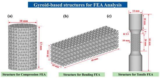
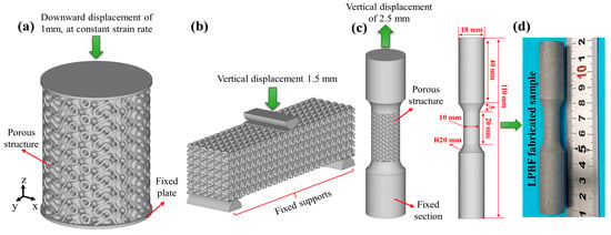
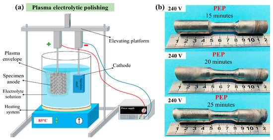
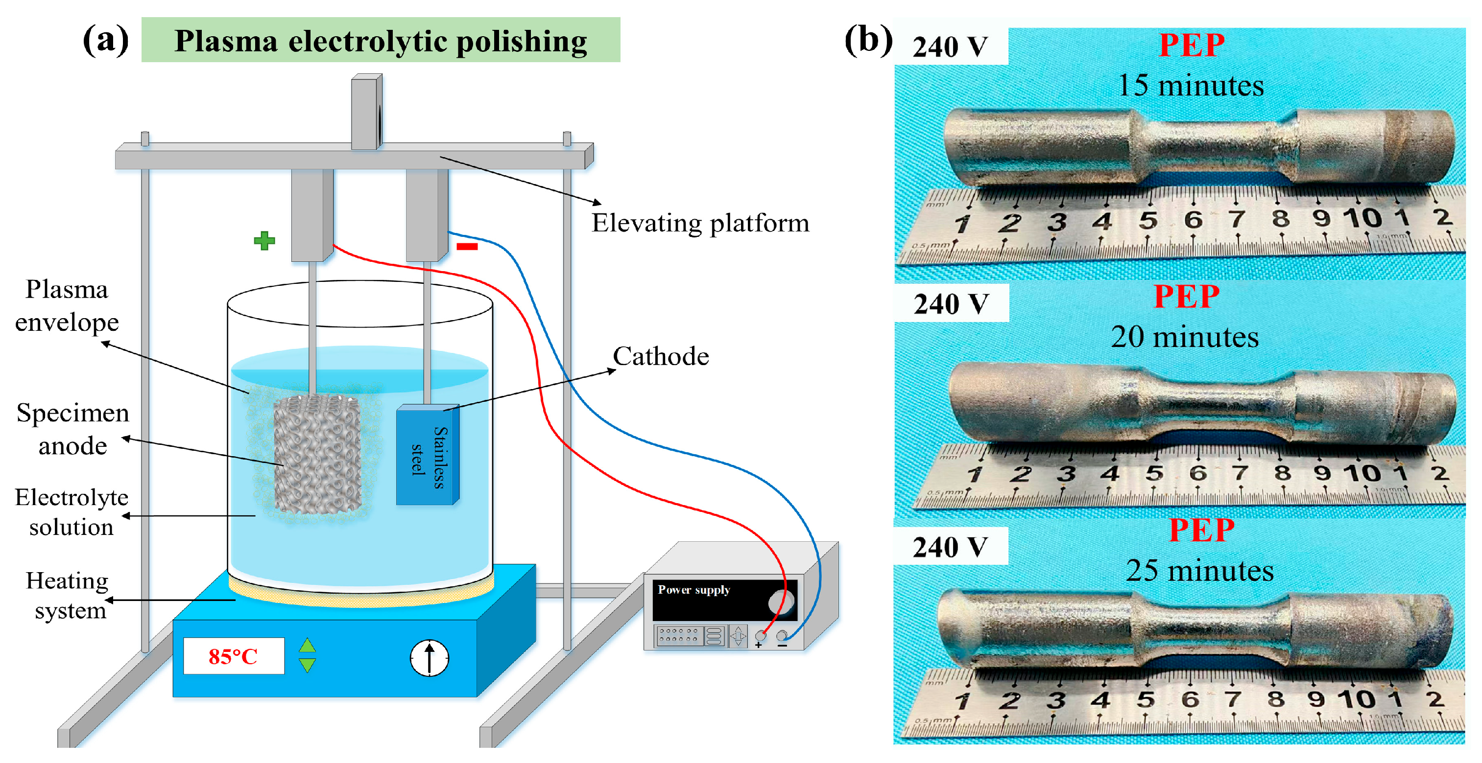
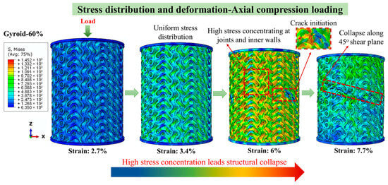
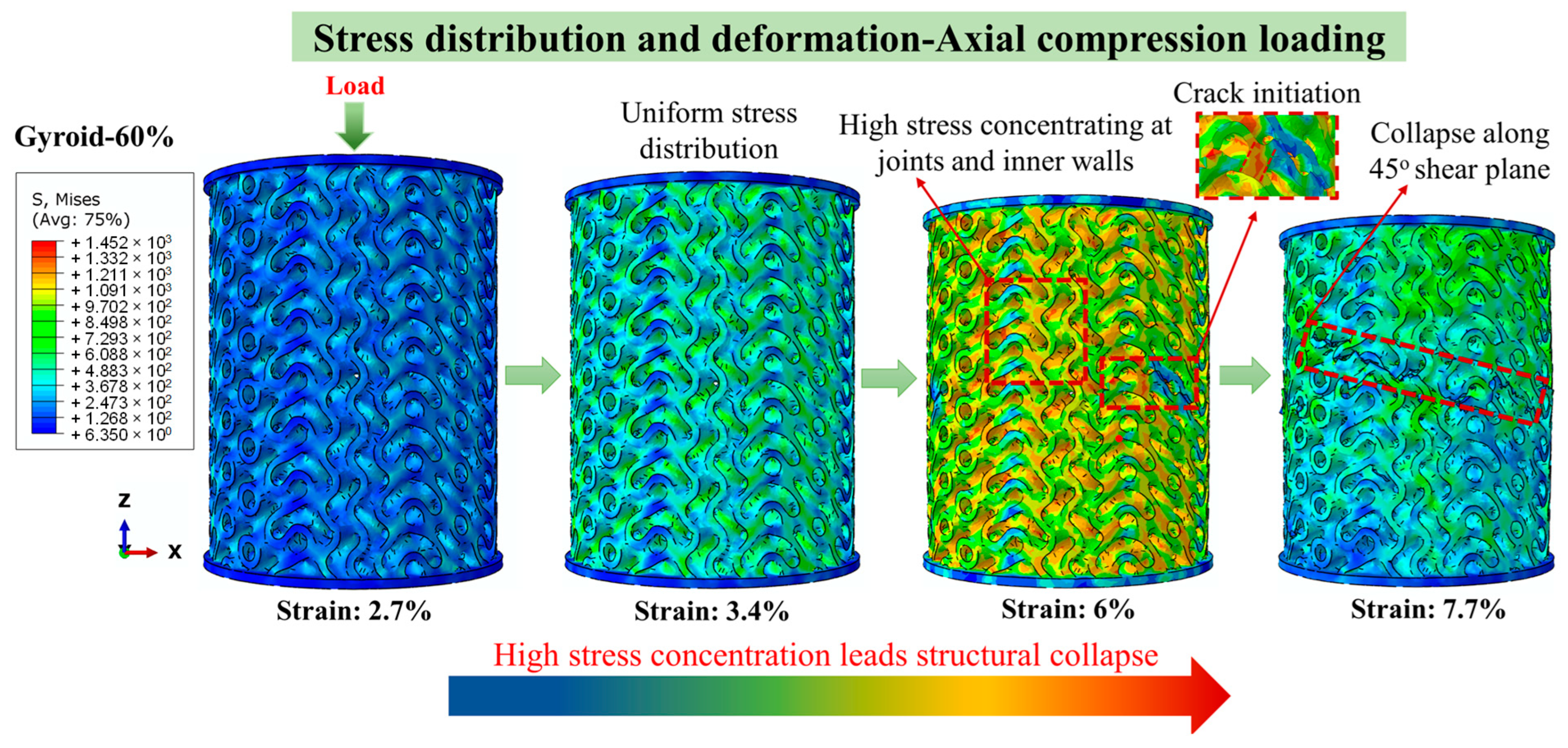
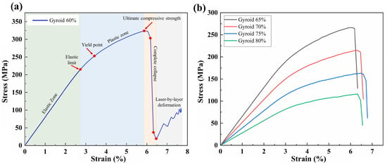
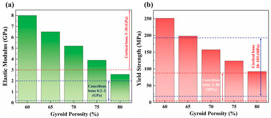
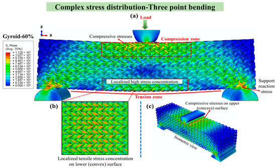
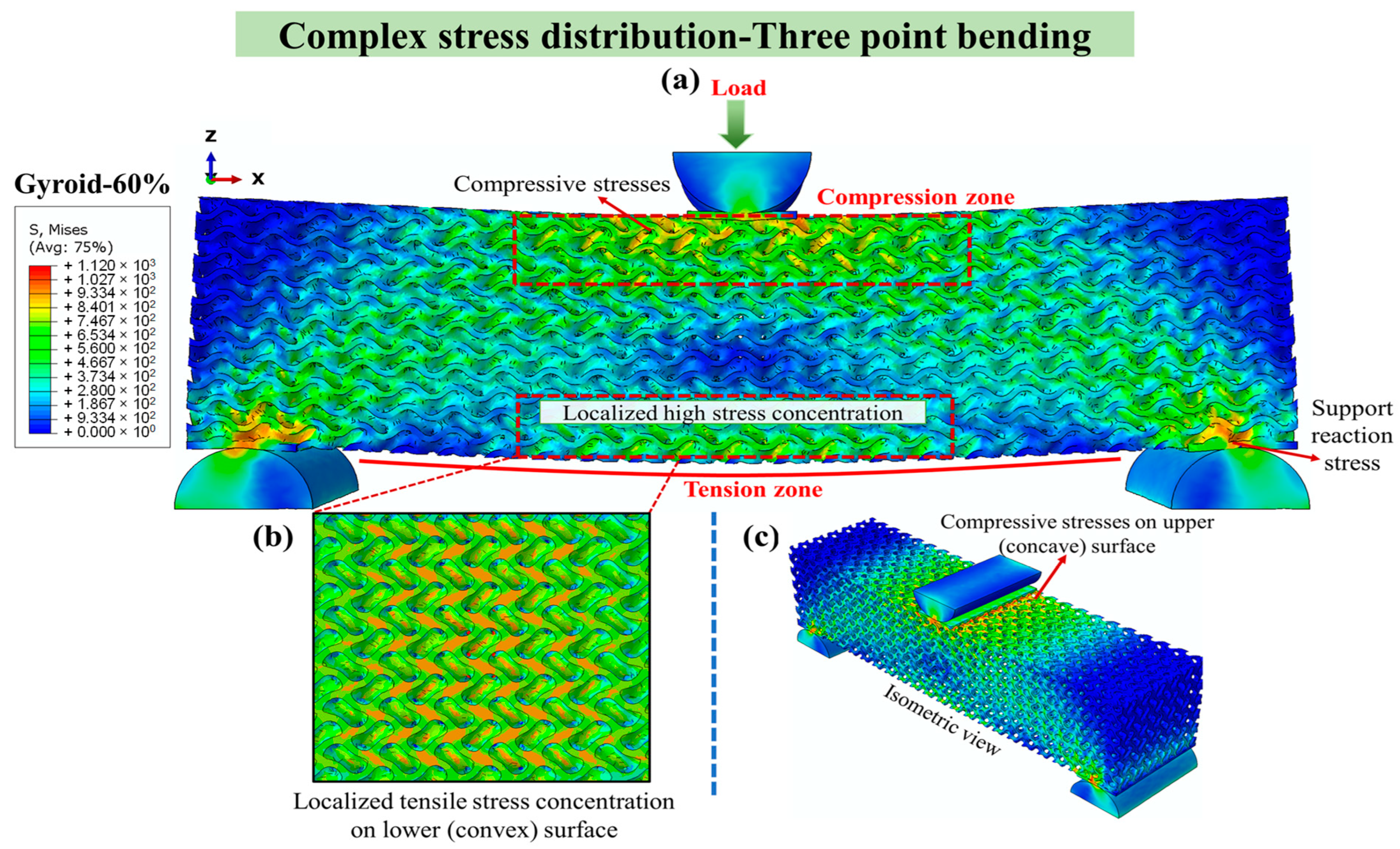
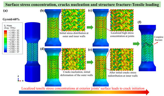
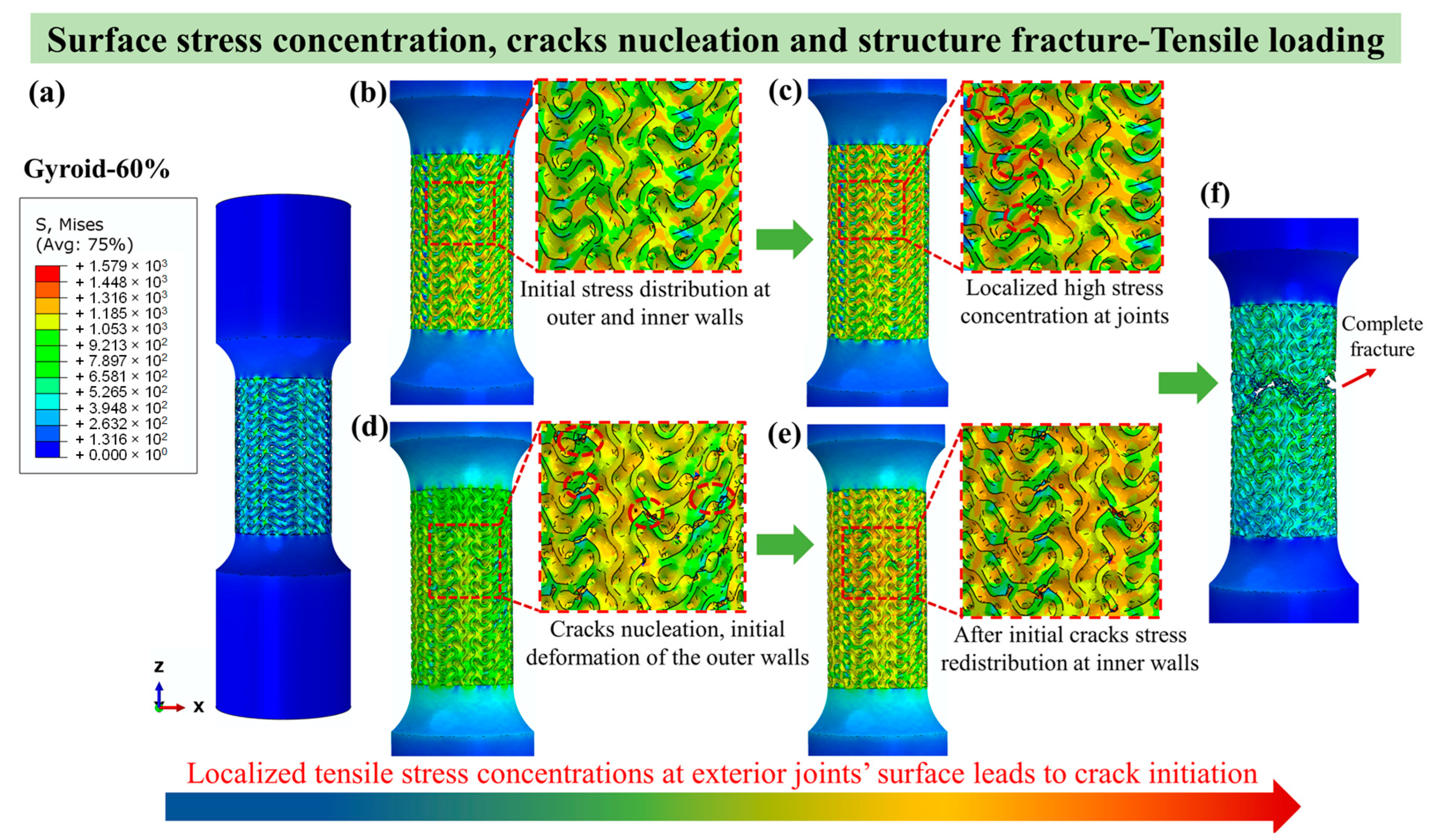
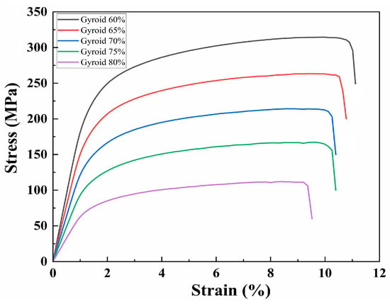
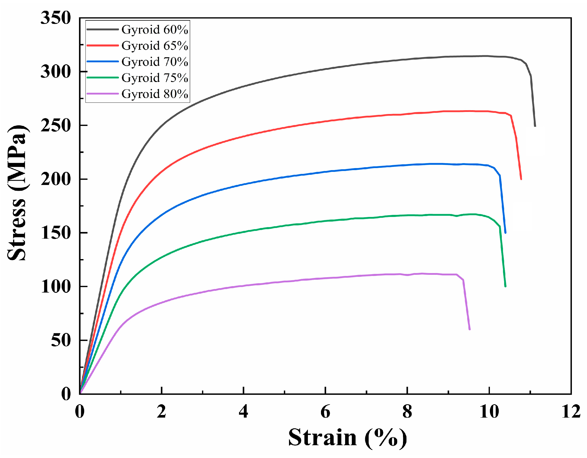
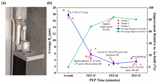
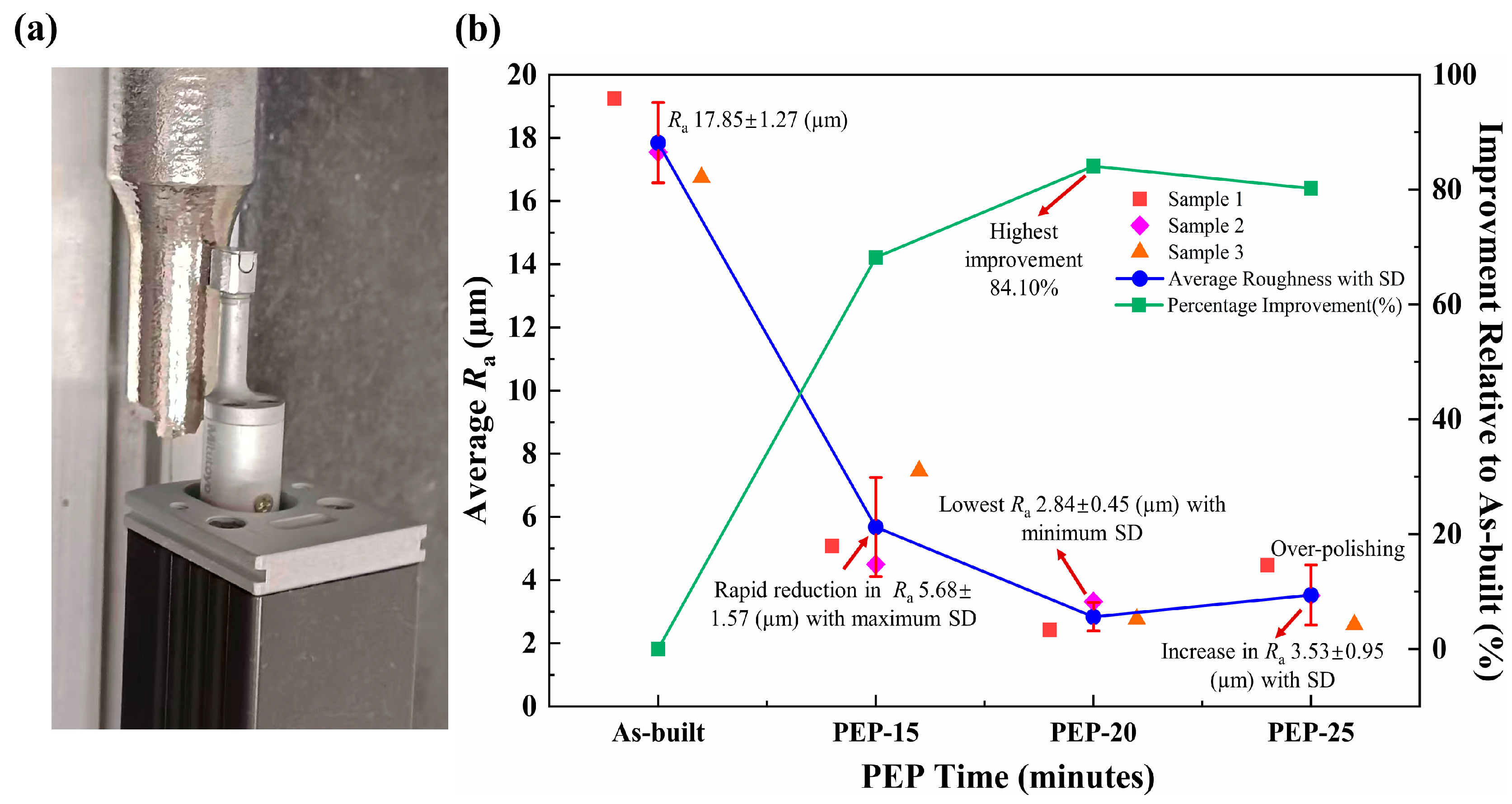
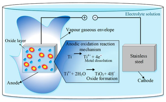
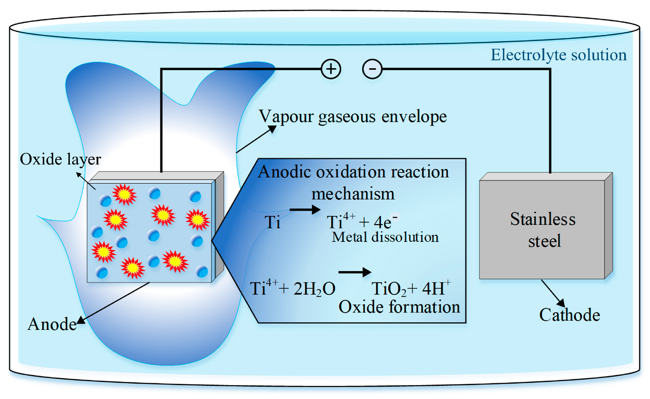
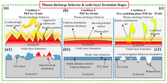
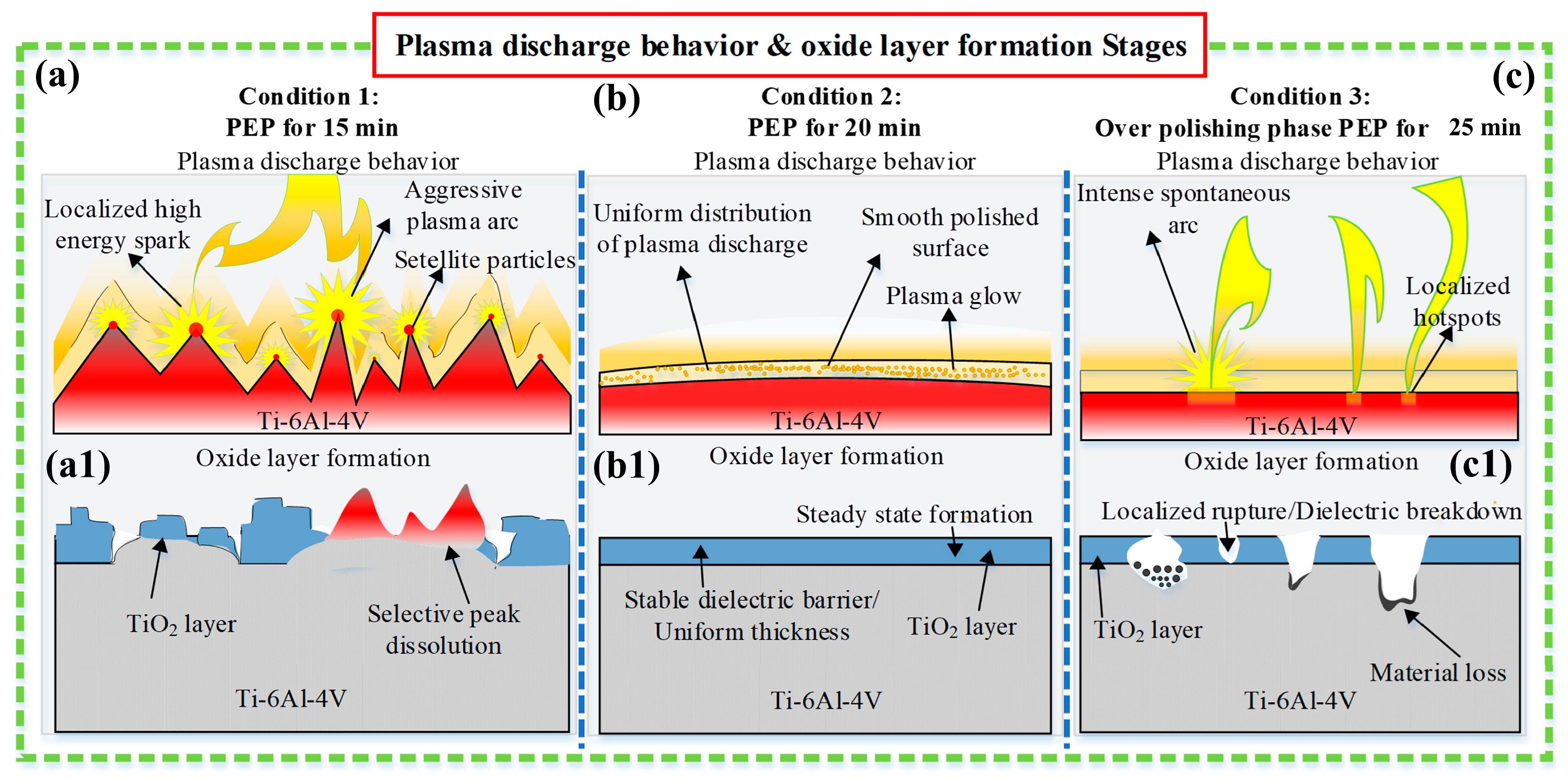
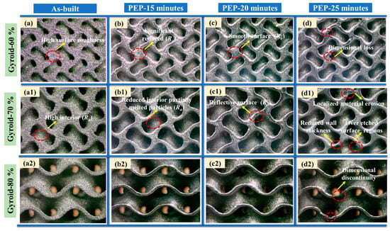
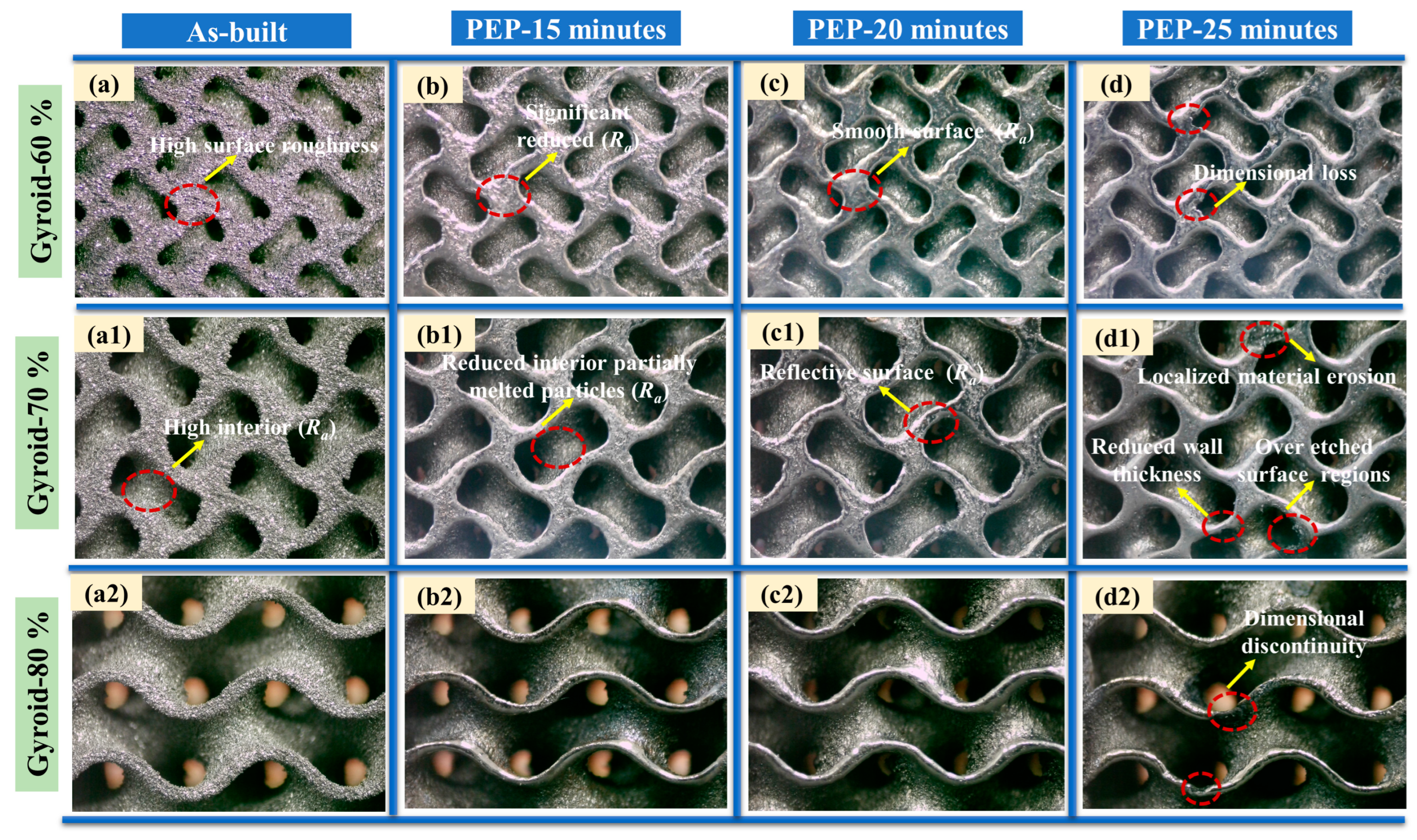
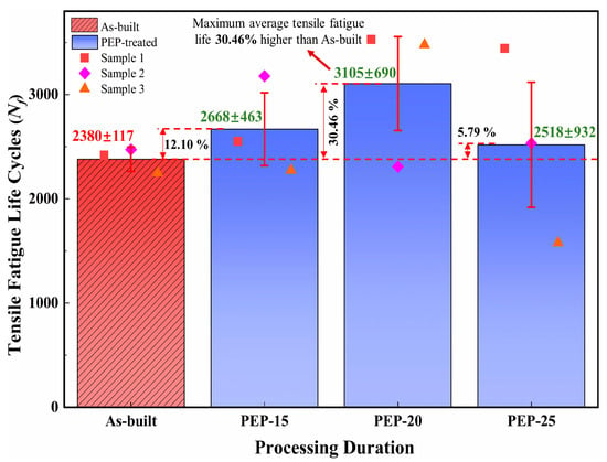
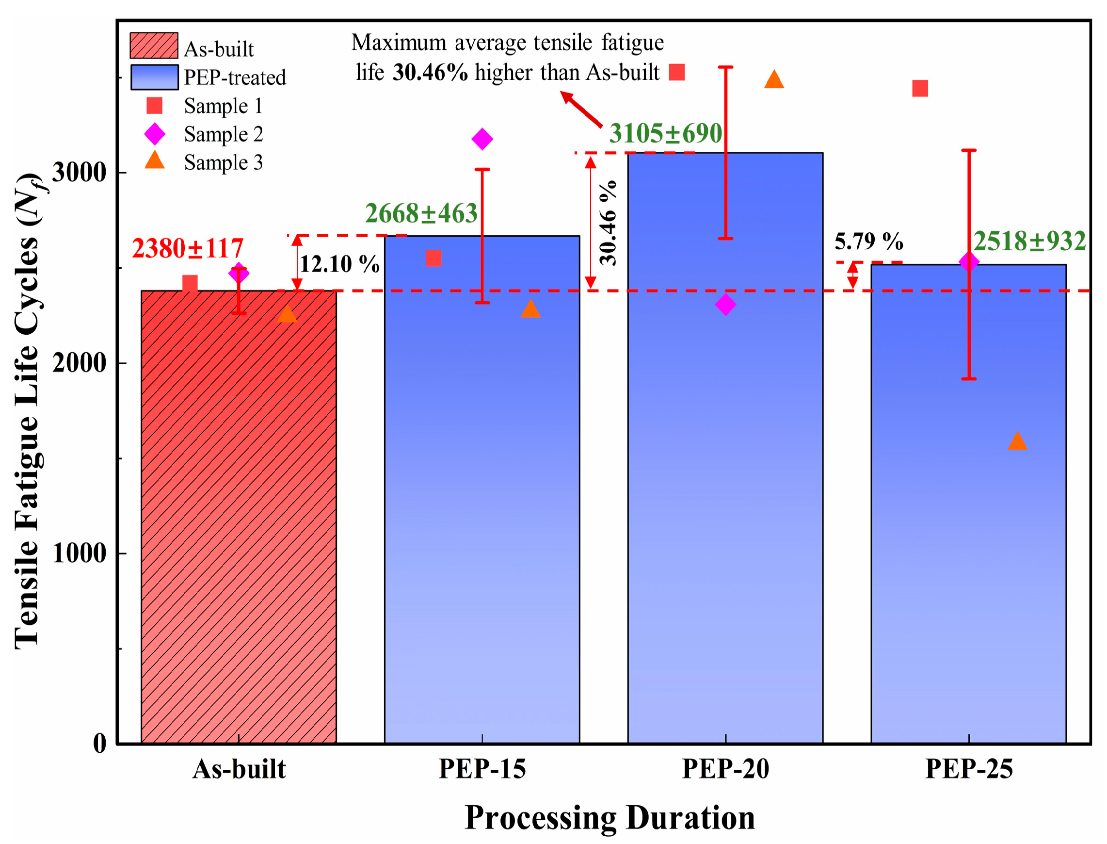
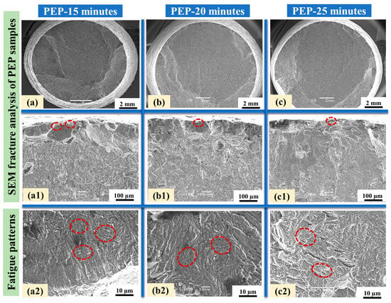
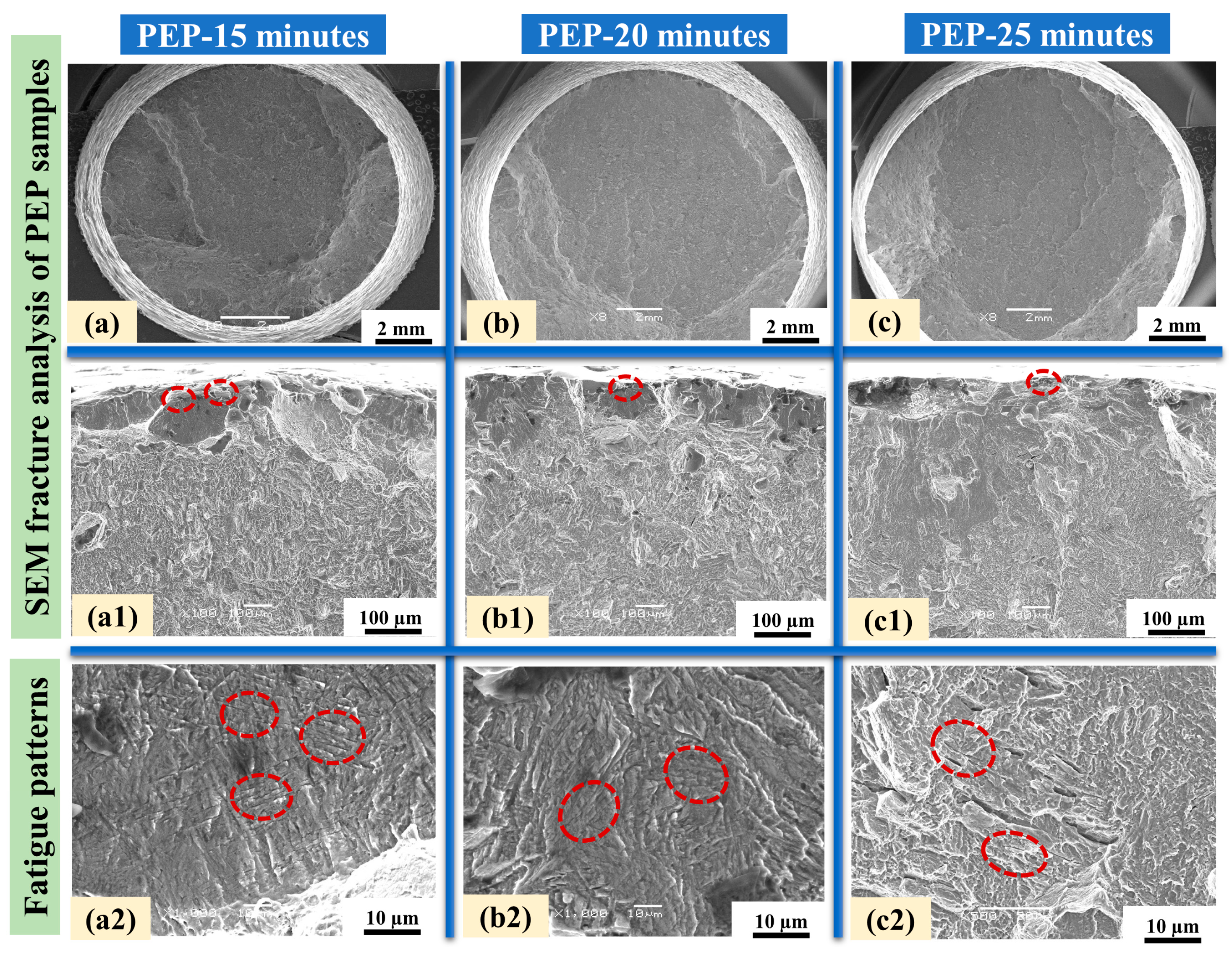

Disclaimer/Publisher’s Note: The statements, opinions and data contained in all publications are solely those of the individual author(s) and contributor(s) and not of MDPI and/or the editor(s). MDPI and/or the editor(s) disclaim responsibility for any injury to people or property resulting from any ideas, methods, instructions or products referred to in the content. |
© 2026 by the authors. Licensee MDPI, Basel, Switzerland. This article is an open access article distributed under the terms and conditions of the Creative Commons Attribution (CC BY) license.