


Abstract
This study experimentally investigates the effect of oxide film thickness on the amplitude of laser-induced stress waves in AISI W1-7 carbon steel. Oxide layers of approximately 0.045 μm (straw-yellow) and 0.07 μm (blue) were synthesized via controlled heating using a free-running YAG:Nd3+ laser. The work used a Q-switched ruby laser (λ = 0.69 μm; FWHM = 25–30 ns; E up to 1.5 J) to generate intense stress waves. The displacement of the sample’s free surface was recorded using a Michelson interferometer with a probing He–Ne laser (λ = 0.6328 μm), which was used to construct the “pressure–time” relationship. It has been established that oxide films with thicknesses of 0.045 and 0.07 μm increase the wave amplitude by 1.15 and 1.4 times, respectively, relative to pure steel, which is associated with enhanced optical absorption and thin-film interference at the laser pump wavelength. Furthermore, the quasi-linear dependence of the stress wave amplitude on the laser pulse energy (0.7–1.5 J) indicates the absence of plasma shielding within this energy range. These findings suggest that controlled thermal oxidation can serve as an effective, clean absorptive coating to optimize laser shock peening (LSP) processes.
1. Introduction
Laser processing of materials occupies an important place among new methods of hardening technologies [1,2,3,4,5]. The improvement of the operational properties of metallic materials in various types of laser surface treatment is associated with a purposeful change in the chemical composition and structural and phase state of the surface films, as a result of which metals and alloys acquire properties in limited volumes that are unattainable with traditional processing methods [6]. One of the new technologies for modifying the surface of materials is Laser Shock Peeling [7], based on the effect of focused pulsed laser radiation of high energy density (I > 108 W/cm2) and short duration (τ < 50 ns) on the metal surface. The physics and mechanisms of shock wave generation by laser radiation pulses are considered in detail in [8]. Areas of application of LSP include technologies aimed at preventing stress corrosion cracking [9] and increasing wear resistance [10,11]. LSP is also used to purposefully change the microstructure and mechanical properties of materials [12,13,14,15]. The most promising processing methods include laser impact molding [16] and processing of additive materials in order to reduce the level of technologically accumulated tensile residual stresses [17]. Combined laser processing methods have become new areas of practical application of LSP [18,19]. LSP is used to implement a laser adhesion test [20]. One of the actual applications of LSP is the laser initiation of energy-saturated materials [21]. For all LSP methods, important parameters are the amplitude and duration of stress pulses, the magnitude of which determines the final result of the technology application. To determine these parameters, numerical modeling of laser shock experiments using various physical models is mainly used [22]. Among the existing approaches, the methodology proposed by a team of researchers led by Fabbro [23] has gained the greatest popularity. This model is primarily used for an approximate calculation of the pressure amplitude in a shock wave.
Experimental measurement of the parameters of laser-induced shock waves is a rather difficult task in practice, due to the small size of the laser impact zone. As a rule, capacitive [24], piezoelectric (PVDF) [25] and piezoresistive sensors [26] are used for this purpose. Due to the uniqueness of their characteristics (non-contact, locality, high resolution, and noise immunity), interferometric methods for determining shock wave parameters are widely used in solving problems of experimental mechanics. The Michelson displacement interferometer and velocity interferometer are the most widely used in the implementation of these techniques [27].
In the context of the practical implementation of technologies based on the LSP method, in some cases, their efficiency and effectiveness are limited by the energy capabilities of technological laser installations. In this case, the efficiency of laser treatment can be increased by changing the irradiation conditions associated with the use of absorbing coatings [28,29]. One of the ways to increase the absorption capacity of laser radiation is to create an oxide film on the surface of the product [30].
The observed enhancement can be explained by complementary mechanisms:
- Increased absorption. The optical properties of oxides differ from those of metallic iron. In the near-infrared region of the spectrum (A = 0.69 μm), the absorption coefficient of iron oxides is usually higher than that of metallic iron. This is largely due to the electronic structure of the oxides.
- Interference in thin films. The oxide layer functions similarly to a dielectric film on the metal surface. Accordingly, the resulting interference, which depends on the thickness of the oxide layer and the wavelength of the incident laser radiation, can affect absorption, either increasing it or decreasing it. In the case where the film thickness (n-d) is a multiple of λ/4 with an odd coefficient, interference occurs, which reduces reflection and increases absorption. The wavelength of the ruby laser (A = 0.69 μm) determines the optical thickness at a quarter of the wavelength and is λ/4 = 0.173 μm. Thus, the determined (or obtained) thicknesses of the oxide layer, 0.045 μm and 0.07 μm, correspond approximately to λ/16 and λ/10. However, the presence of several oxide phases and the surface state lead to a complication of the rather simple quarter-wave model. The blue oxide film (λ = 0.07 μm thick) provides a more significant increase in the absorption of radiation with a wavelength of A = 0.69 μm.
- Improved plasma confinement. The oxide layer can also act as a thermal barrier, reducing the thermal conductivity of the substrate and thereby maintaining higher temperatures in the near-surface layer of the material, which leads to higher pressure values. It is generally believed that the thermal conductivity of iron oxides is typically lower than that of iron, which confirms this hypothesis. The amplitude gain factors observed in this study (1.15 for 0.045 μm and 1.4 for 0.07 μm) are comparable to those reported in the literature for other absorptive coatings. For example, Hruska et al. [20] reported that oxide patterns on C45 steel surfaces increased laser absorption during quenching. Yang et al. [19] demonstrated that nano-coatings can significantly improve absorption in laser processing applications.
However, the literature on quantitative measurements of stress wave amplitude enhancement by oxide films is limited. Most studies focus on the use of sacrificial coatings (black paint, tape, or aluminum foil) which typically provide absorption enhancement factors of 1.5–2.0. The oxide film approach offers several advantages:
- -
- no need for coating application and removal steps
- -
- no contamination of the workpiece surface
- -
- compatible with in-vacuum or clean-room processing
- -
- the oxide layer is an integral part of the material’s surface
The observed enhancement of 1.4 for the 0.07 μm oxide film is significant but slightly lower than what can be achieved with optimized sacrificial coatings. However, the simplicity and cleanliness of the thermal oxidation approach make it attractive for industrial applications.
This paper presents data from laboratory studies devoted to the influence of oxide films on the amplitude characteristics of stress waves generated by laser radiation. The formation of oxide layers on the surface of the samples was carried out using a pulsed YAG:Nd3+ laser operating in free-running mode. A Michelson laser interferometer was used to record the parameters of the excited stress waves.
From a practical standpoint, increasing the peak stress wave amplitude has significant implications for LSP optimization. According to established LSP models, a 1.15 to 1.4-fold increase in peak pressure can theoretically enable a 20–30% reduction in the required laser pulse energy to achieve a target shock pressure, thereby improving energy efficiency. A proportional increase in the depth of the residual compressive stress layer is achieved when the laser energy remains the same, and the oxide layer acts as the absorbing element. Therefore, the primary objective of this study is to quantitatively evaluate the influence of controlled oxide film thickness on the amplitude and propagation of laser-induced stress waves in AISI W1-7 carbon steel, and to assess the technological feasibility of using thermal oxidation as a clean, effective absorptive coating for LSP optimization.
2. Materials and Methods
The AISI W1-7 carbon steel samples (approximate composition: 0.70–0.80% C, 0.25% Si, 0.30% Mn, 0.17% Ni, 0.021% S, 0.020% P) possessed a density of 7850 kg/m3 and a longitudinal elastic wave speed of 5900 m/s. To ensure statistical reliability, each experimental condition (specific oxide thickness and laser energy) was repeated 3 to 5 times on fresh sample areas. The displacement and velocity profiles were extracted from the raw interferometric signals using a custom algorithm that identifies the zero-crossings of the interference fringes (each corresponding to a λ/2 displacement) and applies numerical differentiation. The oscilloscope (Tektronix TDS 2004B, Beaverton, OR, USA) operated at a sampling rate of 2 GS/s with a bandwidth of 200 MHz, providing a temporal resolution of 0.5 ns, which is sufficient to accurately resolve the nanosecond-scale stress wave fronts. The error bars presented in the subsequent figures represent the standard deviation of the repeated measurements.
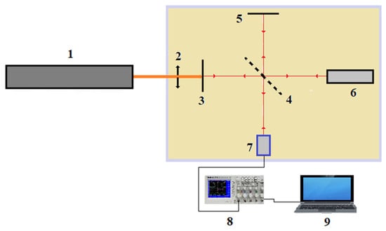
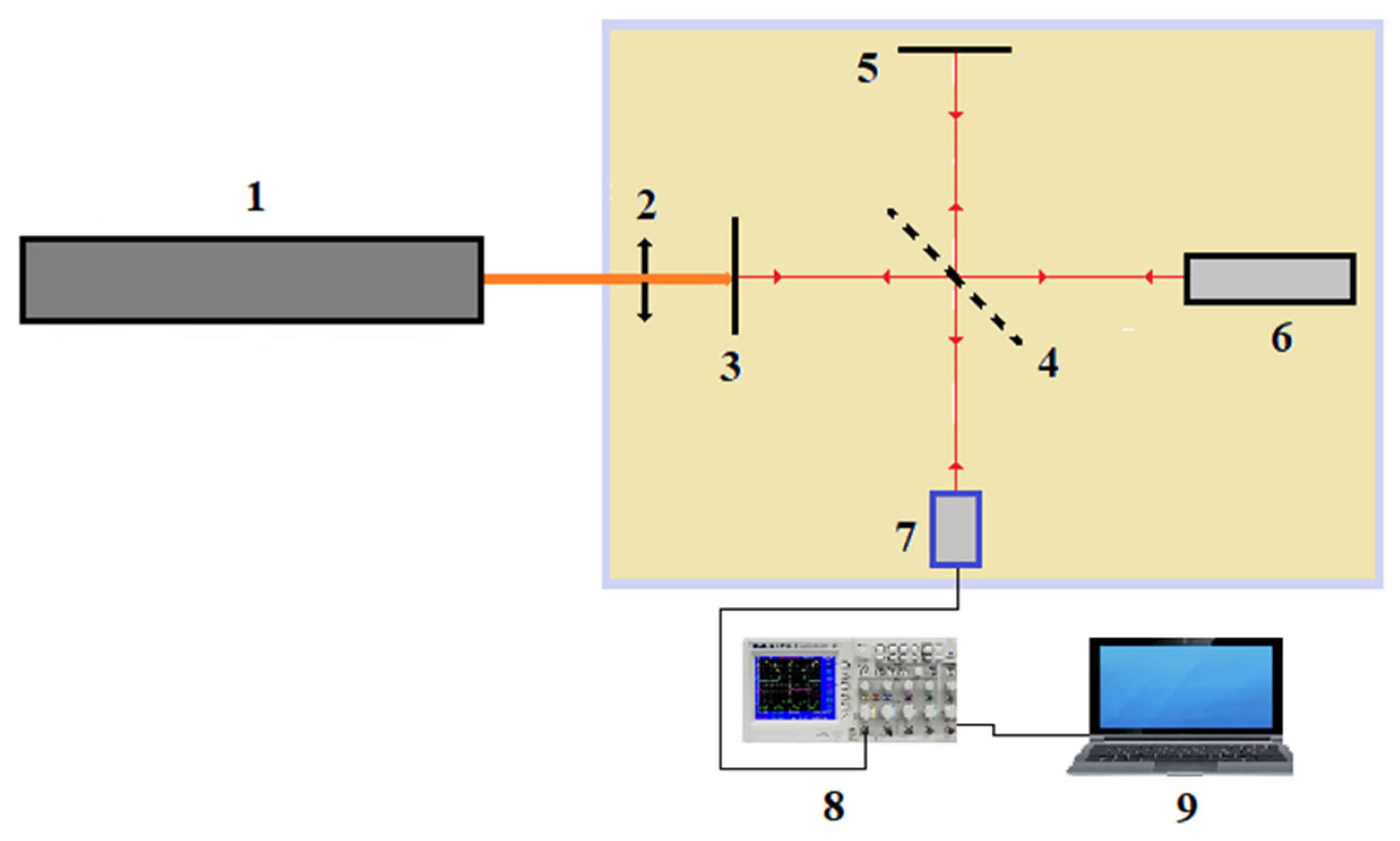
To conduct the experiments, a pilot plant was assembled, the main elements of which were a pulsed ruby laser operating in the modulated Q-switch mode and a Michelson interferometer. The installation diagram is shown in Figure 1. A small-thickness steel sample 1 was exposed on one side to a single pulse of a ruby laser operating in a Q-switch mode. To form one of the arms of the Michelson interferometer, a mirror-polished reverse side of the sample was used. Coherent radiation was generated by a single-mode helium-neon laser (λ = 0.6328 μm). The laser beam was split into two using a semi-transparent mirror 4. The beam reflected from the fixed mirror 5 was considered the reference beam; the beam reflected from the surface of the sample 3 was the probing beam. Due to the Doppler effect, the frequency of the probing beam changes when the sample surface is displaced. After reflection from the stationary mirror and from the moving surface of the sample, the reference and probing beams are combined on a semi-transparent mirror. The resulting interference beam, carrying the difference frequency, reaches the photodetector 1. Since the difference frequency is due to the Doppler shift in the probing beam, the light flux at the photodetector is amplitude-modulated at this frequency.
Figure 1.
Scheme of the experimental setup: 1—ruby laser; 2—focusing lens; 3—sample; 4—translucent mirror; 5—100%; 6—He-Ne laser; 7—photodetector; 8—Tektronix TDS 2004B oscilloscope; 9—personal computer.
A thin steel sample 1 was exposed to a single pulse of the ruby laser on one side. The other side of the sample was mirror-polished and used as a moving mirror of the Michelson interferometer. A single-mode He-Ne laser (λ = 0.6328 μm) was used as the probe radiation source. The beam was split by a beam splitter 4 into a reference beam (reflected from a fixed mirror 5) and a probe beam (reflected from the free surface of the sample 3). As the sample surface moves, the frequency of the probe beam changes according to the Doppler effect. The interfering beams were mixed at the photodetector 7, forming beats.
Due to the fact that no special measures were taken to eliminate mechanical vibrations of the entire interferometer system, individual mirrors could oscillate slightly (due to the transmission of various vibrations through the floor). This property of the system was used to initially tune the interferometer to the maximum suppression of low-frequency oscillations, which corresponded to the best interference conditions. The presence of low-frequency oscillations (10–100 Hz) in the system did not in any way affect the recording of the displacement of the free surface of the sample subjected to impact loading, since the frequencies recorded in this case were ~100 MHz. The presence of low-frequency oscillations in the system affected only the level from which the recording of high-frequency oscillations began on the Tektronix TDS 2004B oscilloscope. The photodetector used in the setup was a laser photodiode LFD-2-A (OJSC RPE “Ulyanovsk Radio Tube Plant”, Russia) with a cutoff frequency of 1 GHz.
The interferometer was adjusted using a sophisticated alignment procedure. A major challenge in the alignment process was the spatial alignment of the axes of the ruby and helium-neon lasers. For this purpose, a 0.1 mm thick plate was used; thin, round holes with a size of about 0.50 mm were formed in it using the radiation from the ruby laser. Then, the reference beam of the interferometer was aligned with the formed hole. Next, prepared samples for research were placed in place of the plate.
The theoretical foundations of displacement interferometry are well known [15]; however, let us recall the basic relations. The output signal of the photodetector U(t) is a sinusoidal function depending on the number of recorded beats N(t):
U(t) = U0 + U1 cos(2π N(t))
The Doppler frequency shift ΔfD for a normally incident beam is related to the free surface velocity V(t) by the relation:
where ΔfD(t) is the Doppler shift; V(t) is the velocity of the free surface; λ is the wavelength of the laser radiation. Integrating (2) over the time of one beat, we obtain that one period of signal oscillations corresponds to a surface displacement:
ΔfD(t) = 2 V(t)/λ,
Δx = λ/2
Consequently, for an arbitrary point in time, the free surface displacement x(t) is defined as:
x(t) = N(t) λ/2
Thus, counting the number of beats on the interferogram allows one to directly reconstruct the surface displacement profile over time. Differentiating x(t) yields the free surface velocity V(t).
The absorption of laser radiation by the near—surface metal layer initiates an acoustic disturbance, a compression wave. The indicated disturbance propagates in the direction of the thickness of the thin-sheet blank and after a certain time interval reaches the opposite free boundary. The interaction of the wave with the free surface leads to an inversion of the sign of mechanical stresses, resulting in the formation of a stretching wave. When the compression wave is reflected from the free surface, the latter begins to move at a velocity V, which is twice the mass velocity of the particles U in the incident compression wave V = 2U. Processing the interferogram yields the time dependence of the displacement of the sample surface x(t). By differentiating it, we obtain the surface displacement velocity V(t) = dx/dt. Based on the recorded velocity of the free surface movement, it becomes possible to calculate the mass velocity of particles in the compression wave U = V/2. If we use the acoustic approximation, which follows from the conservation of momentum for the compression wave, then the amplitude value of the load σ is expressed in terms of the mass velocity U, the density of the medium ρ, and the speed of elastic wave propagation D in the plate material:
σ = ρDU = (ρDV)/2
To achieve high values of specific power on the sample surface, the laser radiation was focused using an aspherical lens with a focal length of 63.5 mm and a diameter of 27.94 mm. At the same time, all components of the interferometer were mounted on a common base in standard frames that ensured precise alignment along three axes (X, Y, Z).
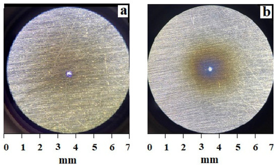
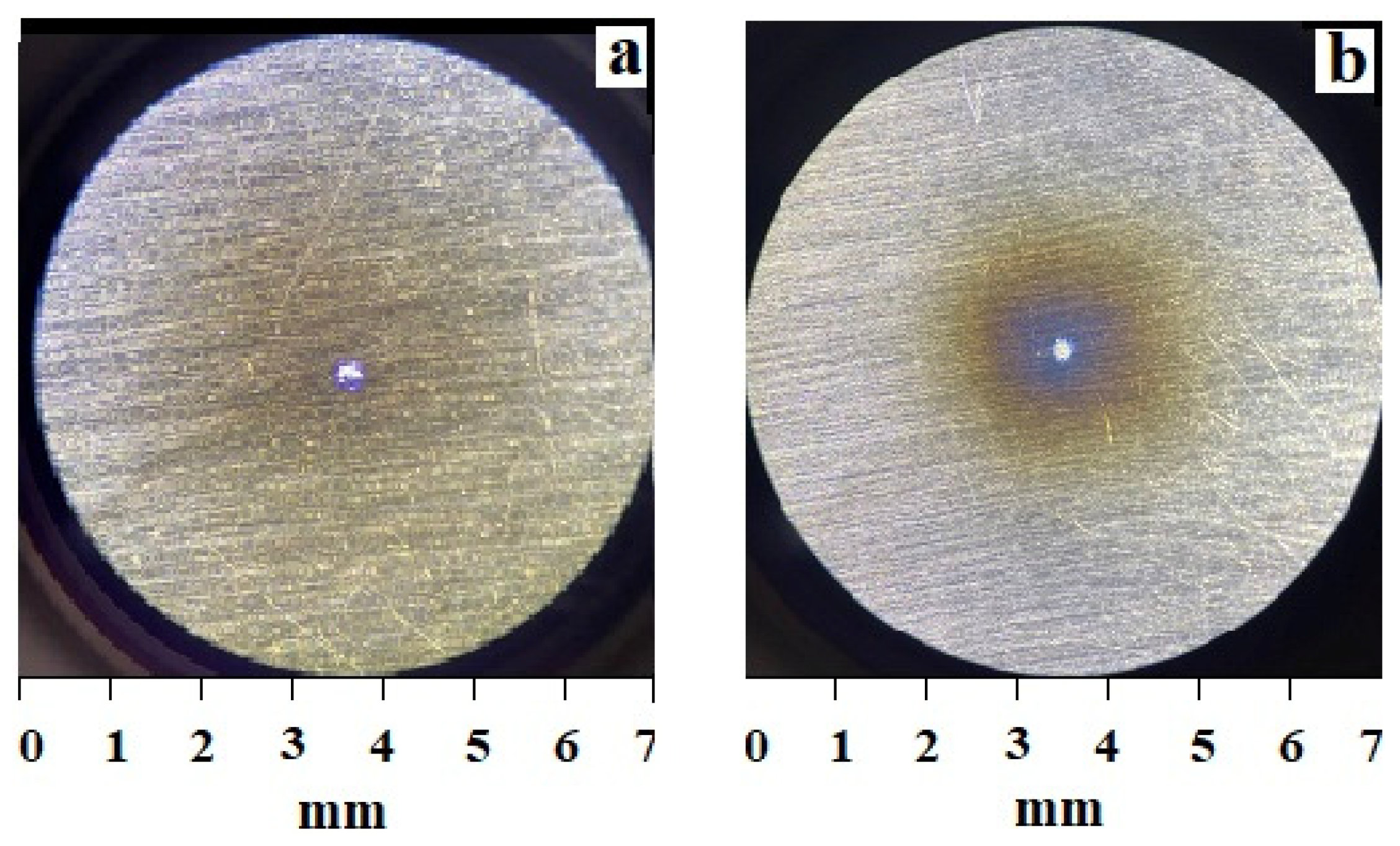
The experiments were carried out on AISI W1-7 steel samples measuring 8 × 16 mm, with a thickness from 0.1 mm to 0.45 mm and a pitch of 0.05 mm. The initial surface roughness Ra was 0.63 microns. One side of the sample, which served as one of the mirrors of the interferometer, was polished to Ra = 0.04 microns. The other side of the sample, on which the oxide film was formed, remained with the initial roughness (Ra = 0.63 microns). The oxide films on this surface of the samples were formed by pulsed radiation YAG:Nd3+ laser operating in free running mode (radiation parameters: wavelength λ = 1.06 µm, pulse duration τ = 10 ms, pulse energy E = 2.0 J, focusing spot diameter 6 mm). Under the specified irradiation conditions, the depth of the oxide film depended on the number of pulses and was fixed by the appearance of streak colors. Two oxide films of different thicknesses were obtained. The first film is straw-yellow (a) with a thickness of ~0.045 microns, after 9–11 pulses of radiation. The second film of blue (b) is ~0.07 microns thick, after 14–15 pulses of radiation (Figure 2). The images were taken after exposure to the surface of the samples to monopulse laser radiation. Since the diameter of the area where the oxide films were grown on the sample was 1.5 mm, this allowed for 5 experiments to be conducted.
Figure 2.
Photos of oxide films on the surface of the samples: (a)—straw-yellow; (b)—blue.
Three sample sets were formed for the research. The first set was characterized by the initial state of the surface; in the second set, the surface was covered with an oxide film about 0.045 μm thick; in the third set, the thickness of the oxide layer was approximately 0.07 μm.
Experiment
To generate pressure pulses, radiation from a ruby laser operating in the modulated Q-switch mode was used. The pulse duration t = 25–30 ns and the diameter of the focus spot ~1.5 mm were unchanged in each experiment. The radiation energy varied in the range from 0.7 to 1.5 joules. To determine the effect of the oxide film thickness on the amplitude of the stress pulses, samples from the first, second, and third groups with a thickness of 0.1 mm were irradiated with single monopulses with an energy of 1.5 J. The attenuation of stress waves was studied on images 0.1–0.45 mm thick without coating, with an oxide film of ~0.045 microns and ~0.07 microns, each of which was irradiated with a pulse with an energy of 1.5 J. The dependence of pressure on the radiation energy was studied on samples of three types with a thickness of 0.1 microns. The radiation energy varied in the range from 0.7 to 1.5 joules.
3. Results and Discussion
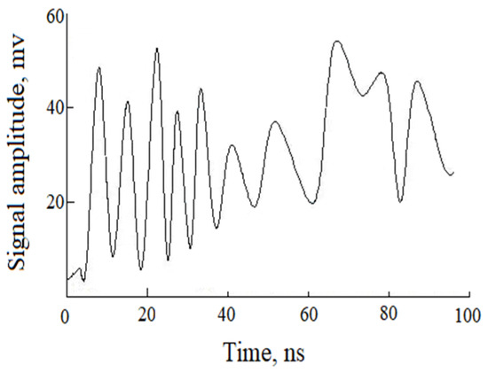
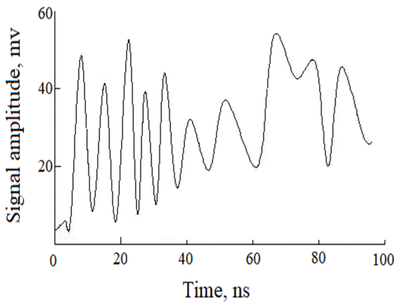
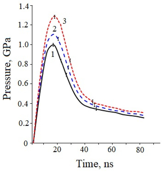
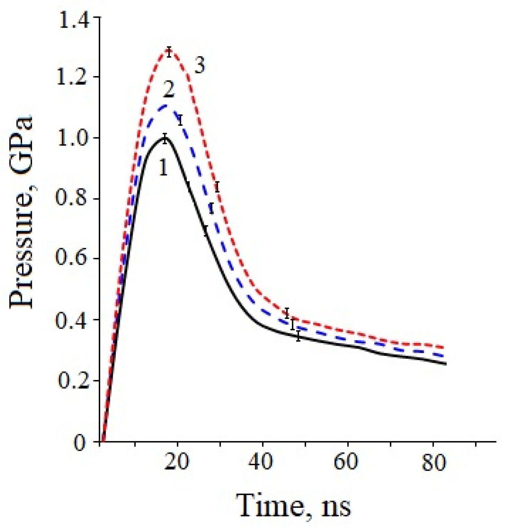
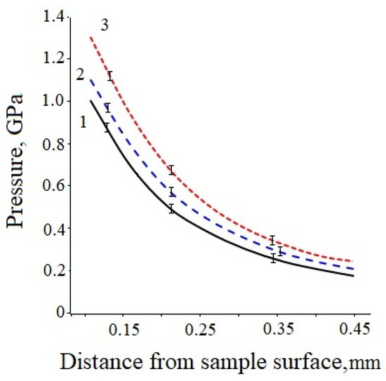
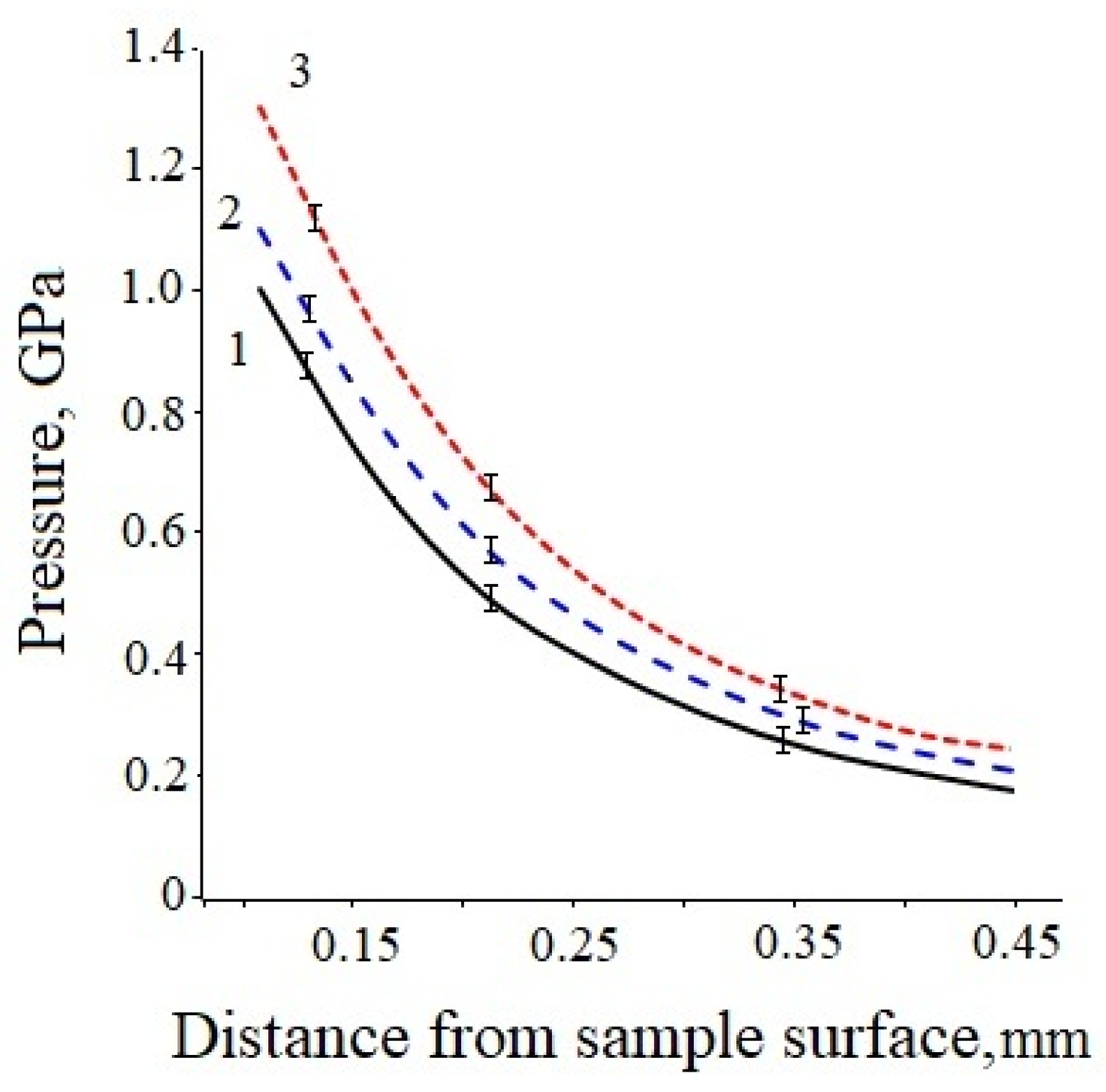
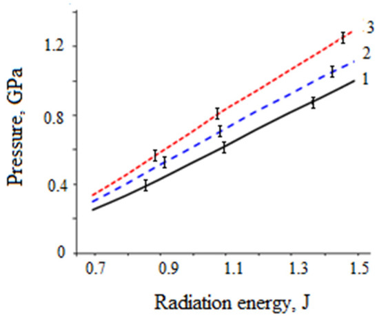
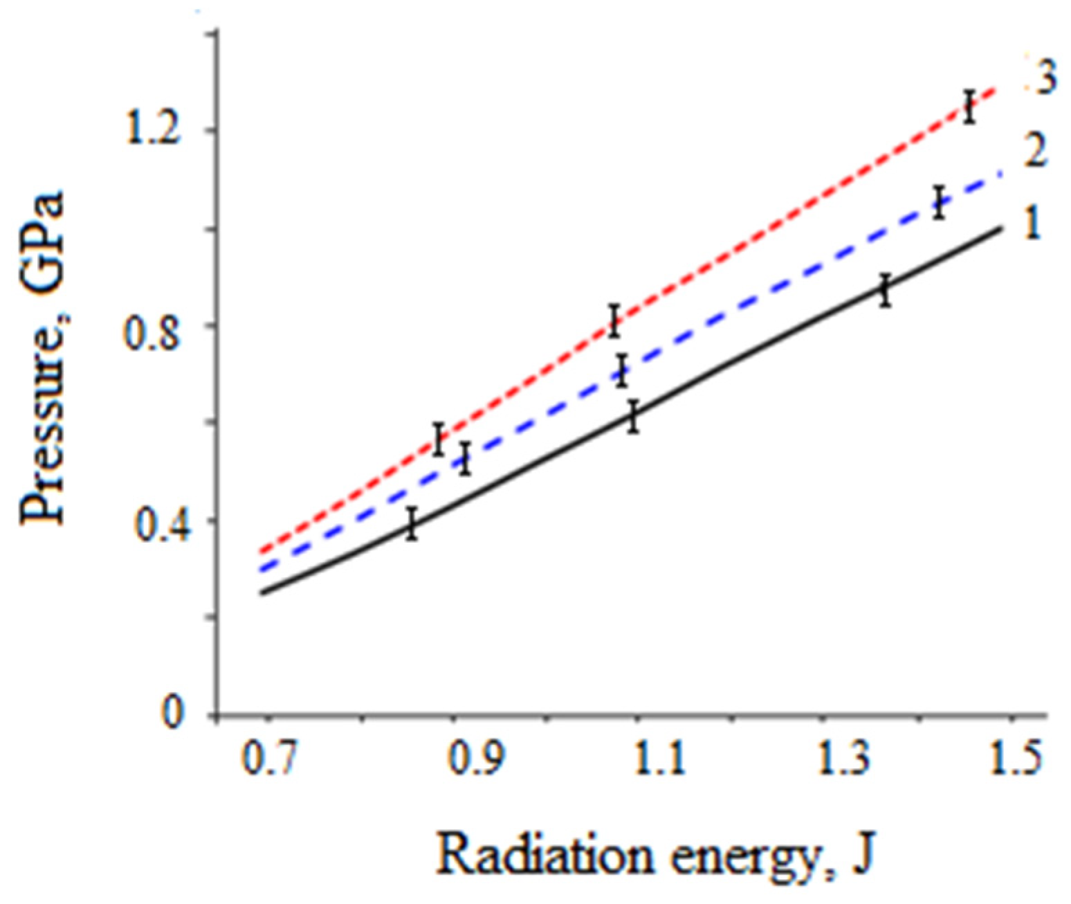
As a result of processing the interferograms (Figure 3), the dependences of the stress pulse amplitude on time (Figure 4), attenuation curves (Figure 5), and energy dependences (Figure 6) were plotted.
Figure 3.
An example of an interferogram obtained in the experiment.
Figure 4.
Pressure dependence on time. 1—uncoated; 2—oxide film ~0.045 microns; 3—oxide film ~0.07 microns.
Figure 5.
Dependence of pressure amplitude on distance. 1—uncoated; 2—oxide film ~0.045 microns; 3—oxide film ~0.07 microns.
Figure 6.
Dependence of the pressure amplitude on the radiation energy of the ruby laser. 1—uncoated; 2—oxide film ~0.045 microns; 3—oxide film ~0.07 microns.
The experimental data indirectly indicates that the presence of a thin oxide layer enhances the absorption of the ruby laser radiation (λ = 0.69 μm). Carbon steel in its initial state has a relatively low reflection coefficient in the red region of the spectrum; however, the formation of iron oxides changes the optical properties of the surface. More efficient energy absorption leads to the generation of plasma with higher pressure, which, according to the Fabbro model, directly increases the peak pressure of the shock wave. It is important to note that the observed dependence of the stress wave amplitude on laser energy it has a slight non-linearity and are valid within the tested parameter ranges (E = 0.7–1.5 J, thin plates 0.1–0.45 mm).
Under identical irradiation parameters (E = 1.5 J), the maximum amplitude of the stress wave was higher for the sample with the blue oxide film (~0.07 μm). The calculated amplitude gain factors were 1.15 for the film with a thickness of ~0.045 μm and 1.4 for the film with a thickness of ~0.07 μm compared to the uncoated sample. The fact that the thicker blue film yields a greater amplitude increase can be attributed not only to the inherent absorption of the oxide but also to the thin-film interference effect, where the film thickness, being a multiple of or close to a quarter of the radiation wavelength, minimizes reflection and maximizes absorption.
Analysis of the attenuation curves (Figure 5) showed a monotonic decrease in the pressure amplitude with an increase in the plate thickness for all types of samples. The nature of the attenuation is determined by the geometric divergence of the shock wave front (spatial scattering effect) and energy dissipation due to the elastoplastic properties of the material. At the same time, samples with an oxide coating demonstrate higher absolute stress values throughout the entire wave propagation depth, which is critical for forming a deep film of residual compressive stresses during laser shock peening.
The dependences of the pressure amplitude on the laser energy (Figure 6) are practically linear for all types of samples in the studied range (0.7–1.5 J). The linearity indicates that the “plasma shielding” (saturation) effect, in which the plasma begins to strongly absorb and scatter the incident laser radiation before it reaches the target surface, is not observed in these experiments. This confirms that the oxide film not only increases the initial absorption but also allows for the efficient conversion of laser energy into mechanical work up to energies of 1.5 J.
Limitations of the study: It is important to recognize certain limitations associated with determining the thickness of the oxide film. Therefore, the thickness of the oxide films was estimated based on the tempering colors (interference colors). The phase composition of the oxides was determined based on data from the literature [31,32].
4. Conclusions
- An experimental study of the effect of oxide film thickness on the parameters of laser-induced stress waves in AISI W1-7 steel was conducted using a laser Michelson interferometer.
- It was established that the formation of thin oxide films with thicknesses of ~0.045 μm and ~0.07 μm on the steel surface leads to an increase in the efficiency of laser radiation absorption and an increase in the pressure of the generated shock wave.
- The amplitude gain factors of the stress pulses were 1.15 and 1.4 for films with thicknesses of ~0.045 μm and ~0.07 μm, respectively.
- It is shown that the linear nature of the dependence of the wave amplitude on the laser energy is maintained for all the studied surfaces, which indicates the absence of the plasma shielding effect in this energy range.
- The obtained results demonstrate the high technological prospects of using controlled oxidation as an absorbing coating for laser shock peening (LSP). The oxide film approach offers several advantages over conventional sacrificial coatings: cleanliness, compatibility with vacuum environments, elimination of coating application/removal steps, and the potential for selective area treatment.
- From a practical perspective, the 1.4-fold increase in peak pressure obtained with the ~0.07 μm oxide film could enable a 20–30% reduction in laser pulse energy for a given shock pressure, or alternatively, a 30–50% increase in the depth of compressive residual stresses at constant laser energy. These benefits can significantly improve the cost-effectiveness and performance of LSP processes in industrial applications.
Author Contributions
Conceptualization, E.R., G.G. and A.K.; methodology, E.R., E.B. and G.G.; software, E.R.; formal analysis, E.B.; investigation, E.R., E.B., G.G. and A.K.; resources, E.R., A.K., G.G. and E.B.; data curation, E.R.; writing—original draft preparation, E.R., E.B. and A.K.; writing—review and editing, E.R., A.K. and G.G.; supervision, A.K.; project administration, E.R. and A.K. All authors have read and agreed to the published version of the manuscript.
Funding
This research was funded by the Ministry of Science and Higher Education of the Russian Federation (agreement No. 075-15-2026-024 dated 04.03.2026 (NNSTU), topic FFUF-2024-0031, No 1023032800130-3-2.3.2 (IAP RAS)).
Data Availability Statement
The original contributions presented in this study are included in the article. Further inquiries can be directed to the corresponding author.
Conflicts of Interest
The authors declare no conflicts of interest.
References
- Padmanabham, G.; Bathe, R. Laser Materials Processing for Industrial Applications. Proc. Natl. Acad. Sci. India Sect. A Phys. Sci. 2018, 88, 359–374. [Google Scholar] [CrossRef] [Scilit]
- Ma, J.; Chen, C. Progress in research on laser shock peening applications. Int. J. Adv. Manuf. Technol. 2026, 143, 6145–6178. [Google Scholar] [CrossRef] [Scilit]
- Ayeb, M.; Frija, M.; Fathallah, R. Laser Peening: A Review of the Factors, Effects, Applications, Comparison with Shot Peening and State-of-the-Art. Met. Mater. Int. 2024, 30, 259–283. [Google Scholar] [CrossRef] [Scilit]
- Deng, W.; Wang, C.; Lu, H.; Meng, X.; Wang, Z.; Lv, J.; Luo, K.; Lu, J. Progressive developments, challenges and future trends in laser shock peening of metallic materials and alloys: A comprehensive review. Int. J. Mach. Tools Manuf. 2023, 191, 104061. [Google Scholar] [CrossRef] [Scilit]
- John, M.; Ralls, A.M.; Kuruveri, U.B.; Menezes, P.L. Tribological, Corrosion, and Microstructural Features of Laser-Shock-Peened Steels. Metals 2023, 13, 397. [Google Scholar] [CrossRef] [Scilit]
- Kapustynskyi, O.; Višniakov, N. Laser Treatment for Strengthening of Thin Sheet Steel. Adv. Mater. Sci. Eng. 2020, 2020, 5963012. [Google Scholar] [CrossRef] [Scilit]
- Cao, X.; Zhong, J.; Wu, X.; Chen, X. Laser Shock Peening: Fundamentals and Mechanisms of Metallic Material Wear Resistance Improvement. Materials 2024, 17, 909. [Google Scholar] [CrossRef] [Scilit] [PubMed]
- Clauer, A.H. Laser Shock Peening, the Path to Production. Metals 2019, 9, 626. [Google Scholar] [CrossRef] [Scilit]
- Sundar, R.; Ganesh, P.; Gupta, R.K.; Ragvendra, G.; Pant, B.K.; Kain, V.; Ranganathan, K.; Kaul, R.; Bindra, K.S. Laser Shock Peening and its Applications: A Review. Lasers Manuf. Mater. Process. 2019, 6, 424–463. [Google Scholar] [CrossRef] [Scilit]
- Wu, J.; Zhou, Z.; Lin, X.; Qiao, H.; Zhao, J.; Ding, W. Improving the Wear and Corrosion Resistance of Aeronautical Component Material by Laser Shock Processing: A Review. Materials 2023, 16, 4124. [Google Scholar] [CrossRef] [Scilit] [PubMed]
- Yang, S.; Zhang, M.; Yu, P.H.; Sun, Y.F.; Su, Y.; Yu, X.F. Effect of laser shock peening overlap rate on microstructure and wear resistance of M50 steel. Opt. Laser Technol. 2025, 184, 112548. [Google Scholar] [CrossRef] [Scilit]
- Zhou, L.; He, W. Mechanical Behavior and the Strengthening Mechanism of LSP-Induced Gradient Microstructure in Metal Materials. In Gradient Microstructure in Laser Shock Peened Materials; Springer Series in Materials Science; Springer: Singapore, 2021; Volume 314. [Google Scholar] [CrossRef] [Scilit]
- Song, Y.; Wu, C.; Ma, H. Laser Shock Peening: Developments and Mechanical Property Enhancements. In ICAMEM 2024, Proceedings of the 13th International Conference on Advanced Materials and Engineering Materials, Dubai, United Arab Emirates, 16–18 December 2024; Zhang, L., Ed.; Springer Proceedings in Physics; Springer: Singapore, 2025; Volume 324. [Google Scholar] [CrossRef] [Scilit]
- Thangamani, G.; Kumar Tamang, S.; Patel, M.S.; Arackal Narayanan, J.; Thangaraj, M.; Zhang, J.; Kumar Gianchandani, P.; Iyamperumal Anand, P. Studies on the effect of laser shock peening intensity on the mechanical properties of wire arc additive manufactured SS316L. J. Manuf. Mater. Process. 2025, 9, 8. [Google Scholar] [CrossRef] [Scilit]
- Li, K.; Yu, W.; Li, Y.; Bao, H.; Cao, Y.; Wang, Y. Study on the effects of laser shock peening on the microstructure and properties of 17-7PH stainless steel. Front. Mater. 2024, 11, 1484698. [Google Scholar] [CrossRef] [Scilit]
- Zhang, T.; Wang, X.; Zhang, D.; Gong, Q.; Shen, Z.; Hou, X.; Liu, H. Laser shock micro-sheet bulk metal forming: Numerical simulation and experimental validation. Int. J. Mater. Form. 2023, 16, 2. [Google Scholar] [CrossRef] [Scilit]
- Munther, M.; Martin, T.; Tajyar, A.; Hackel, L.A.; Beheshti, A.; Davami, K. Laser shock peening and its effects on microstructure and properties of additively manufactured metal alloys: A review. Eng. Res. Express 2020, 2, 022001. [Google Scholar] [CrossRef] [Scilit]
- Bragov, A.M.; Lomunov, A.K.; Rusin, E.E.; Gavrilov, G.; Kurkin, A. Effect of Combined Laser Thermal and Shock Wave Effects on the Mechanical and Tribological Properties of Steels. Materials 2024, 17, 1809. [Google Scholar] [CrossRef] [Scilit] [PubMed]
- Liu, S.; Kim, Y.; Jung, J.; Bae, S.; Jeong, S.; Shin, K. Effect of Ultrasonic Shot Peening and Laser Shock Peening on the Microstructure and Microhardness of IN738LC Alloys. Materials 2023, 16, 1802. [Google Scholar] [CrossRef] [Scilit] [PubMed]
- Kanamori, K.; Toriumi, S.; Kimoto, Y.; Yonezu, A. Repeated Laser Shock-Wave Adhesion Test for Metallic Coatings: Adhesion Durability and Its Mechanism Studied by Molecular Dynamics Simulation. Coatings 2021, 11, 291. [Google Scholar] [CrossRef] [Scilit]
- Tverjanovich, Y.; Tverjanovich, A.; Averyanov, A.; Panov, M.; Ilyshin, M.; Balmakov, M. Interaction of Laser Radiation with Explosives, Applications and Perspectives. Prog. Photon Sci. 2019, 119, 493–511. [Google Scholar] [CrossRef] [Scilit]
- Cuenca, E.; Ducousso, M.; Rondepierre, A.; Videau, L.; Cuvillier, N.; Berthe, L.; Coulouvrat, F. Propagation of laser-generated shock waves in metals: 3D axisymmetric simulations compared to experiments. J. Appl. Phys. 2020, 128, 244903. [Google Scholar] [CrossRef] [Scilit]
- Berthe, L.; Fabbro, R.; Peyre, P.; Tollier, L.; Bartnicki, E. Shock waves from a water-confined laser-generated plasma. J. Appl. Phys. 1997, 82, 2826–2832. [Google Scholar] [CrossRef] [Scilit]
- Li, X.; Duan, Z.; Long, R. Research on vibration compensation technology of pressure sensors in shock wave overpressure measurement. J. Phys. Conf. Ser. 2022, 2369, 012075. [Google Scholar] [CrossRef] [Scilit]
- Nie, X.F.; Tang, Y.Y.; Li, Y.; Yan, L.; Wu, H.N. Effects of confining layer and ablating layer on laser-induced shock wave characteristics during laser shock processing by PVDF gauge. J. Phys. Conf. Ser. 2021, 1980, 012011. [Google Scholar] [CrossRef] [Scilit]
- Gonzalez-Romero, R.; Strojnik, M.; Garcia-Torales, G.; Gomez-Rosas, G. Frequency Dependence of a Piezo-Resistive Method for Pressure Measurements of Laser-Induced Shock Waves in Solids. Photonics 2021, 8, 120. [Google Scholar] [CrossRef] [Scilit]
- Barker, L.M. Laser interferometry in shock-wave research. Exp. Mech. 1972, 12, 209–215. [Google Scholar] [CrossRef] [Scilit]
- Yang, Y.; Zhang, Y.; He, T. Research on Nano-Coating Absorption Application in Laser Processing. Adv. Mater. Res. 2010, 139–141, 464–467. [Google Scholar] [CrossRef] [Scilit]
- Liu, W.J.; Sun, Y.F.; Yu, X.F.; Su, Y.; Li, C.G. Effect of the Absorption Layer on the Microstructure and Mechanical Properties of M50 Steel by Laser Shock Peening. JOM 2024, 76, 7247–7258. [Google Scholar] [CrossRef] [Scilit]
- Hruska, M.; Vostrak, M.; Tesar, J. The influence of oxide layer pattern size created on the surface of C45 steel on laser light absorption during laser quenching procedure. IOP Conf. Ser. Mater. Sci. Eng. 2018, 461, 012027. [Google Scholar] [CrossRef] [Scilit]
- Sidashov, A.V.; Kozakov, A.T.; Yares’ko, S.I.; Kakovkina, N.G.; Manturov, D.S. Phase composition and tribological characteristics of surface layers of carbon tool steels after laser treatment in air. Surf. X-Ray Synchrotron Neutron. Res. 2021, 4, 47–58. [Google Scholar] [CrossRef] [Scilit]
- Hayashi, S.; Mizumoto, K.; Yoneda, S.; Kondo, Y.; Tanei, H.; Ukai, S. The Mechanism of Phase Transformation in Thermally-Grown FeO Scale Formed on Pure-Fe in Air. Oxid. Met. 2014, 81, 357–371. [Google Scholar] [CrossRef] [Scilit]
Disclaimer/Publisher’s Note: The statements, opinions and data contained in all publications are solely those of the individual author(s) and contributor(s) and not of MDPI and/or the editor(s). MDPI and/or the editor(s) disclaim responsibility for any injury to people or property resulting from any ideas, methods, instructions or products referred to in the content. |
© 2026 by the authors. Licensee MDPI, Basel, Switzerland. This article is an open access article distributed under the terms and conditions of the Creative Commons Attribution (CC BY) license.