


Abstract
Flux-modulating machines are emerging as noteworthy machines, particularly in wind turbines. Due to their brushless medium-speed operations, they can be deployed for applications where reliability is a critical factor. Two popular machines in this category are brushless doubly fed machines (BDFMs) and wound-field flux-switching machines (WFFSMs). Although these machines work according to similar flux cross-coupling principles, they have almost contrasting descriptions. While the low power density (power per volume) of BDFMs is well documented in the literature, WFFSMs are commonly touted for their high power densities. In this paper, the performances of BDFMs and WFFSMs are compared to harmonize the perspective on their performances in wind generation applications. It is revealed that the compared BDFM and WFFSM topologies have identical performances with some notable nuances. They generate similar power for a given volume, with the WFFSM having greater efficiency, but they have lower power factors. Compared with conventional topologies like doubly fed induction generators, both flux-modulating topologies have considerably lower power densities. Nevertheless, it has been demonstrated that some design insights for one topology (WFFSM or BDFM) are transferable to the other, such as high-performing pole-pair combinations and magnetic loadings. It should also be noted that design developments such as dual stator configurations are beneficial for both topologies, as they enable significant increases in the power generated for a given volume.
1. Introduction
Environmental concerns have given rise to the large-scale adoption of renewable energy. As energy demands increase, renewable energy installations have continued to increase despite policy and financial upheavals [1]. Wind energy is a commonly used renewable energy resource, and there is an increasing focus on offshore wind sites that have a consistent supply of strong winds. These abundant winds lead to higher energy yields compared to onshore sites [2].
Due to the generally treacherous nature of offshore sites, installation and maintenance costs are high. As a result, reliability is greatly desired for the components of wind turbines. Generators are a key component of wind turbines (WTs). Therefore, generator selection is critical for offshore applications [3]. While conventional high-speed generators require multistage gearboxes that fail, gearboxes are not required in direct-drive systems, leading to improved reliability. However, direct-drive generators have low power density (power per volume. Therefore, a balance between power density and reliability has been posited for medium-speed generators [4].
Doubly fed induction generators (DFIGs) are the most widely used wind generators onshore [5], but they are not best suited for offshore operations due to potential downtimes with their slip rings and brushes [6]. Naturally, machine topologies that offer brushless operations are better suited. Permanent magnet (PM) machines are typically brushless, and they have high power densities and efficiencies. However, rare-earth PMs are expensive with unstable supply [7]. PMs also run risks of demagnetization in the presence of strong opposing magnetic fields or at high temperatures [8]. Consequently, there is a growing body of research on non-PM brushless machine alternatives.
Different electrically excited flux-modulating machines are emerging as interesting prospects for non-PM brushless machines. These include topologies like brushless doubly fed machines (BDFMs), flux-reversal machines, DC-excited vernier reluctance machines (DC-VRMs) and wound-field flux-switching machines (WFFSMs). Typically, two sets of windings that do not couple directly are housed in their stators. A modulating rotor is used to cross-couple stator windings [9,10]. They can be built at a cheaper cost compared to PM machines and have no demagnetization concerns. The flux modulation process of fields with different poles results in these machines typically operating at medium speeds considering conventional grid frequencies.
Although they are not descendants of DFIGs, BDFMs are viewed as alternatives to DFIGs, given the similarities of operations. It is generally acknowledged that BDFMs have inferior power densities and efficiencies compared to DFIGs [11,12]. Typically, characteristics like reliability, easier construction for medium-speed operations, and better low-voltage ride-through capabilities are highlighted as advantages of BDFMs. As a result, a lot of research is emerging on their design and control [12,13,14,15,16].
According to [17], topologies like field-excited flux-switching and flux-reversal machines are derivatives of PM-excited machines. It is highlighted that flux-switching topologies have better performances compared to other electrically excited derivatives. The torque per cost is also noted to be higher than PM machines. Furthermore, it is not uncommon to see flux-switching machines described as having high torque densities [17,18,19]. In [20], WFFSMs are proposed for MW medium-speed wind generation, while BDFMs are described as large-scale machines. Similarly to BDFMs, several studies on the development of WFFSMs have been published [21,22].
Despite similarities in operations, overarching brushless wind energy applications, and emerging popularity, there is not really any direct comparison of BDFMs and WFFSMs in the literature. Consequently, in this paper, an attempt is made to calibrate the relative power densities (including efficiencies and power factors) of BDFMs and WFFSMs. Optimized designs of both topologies are obtained for the size of a D400 frame and compared. The designs are also compared with optimized designs from conventional topologies like DFIGs and electrically excited synchronous machines (EESMs). The comparisons with conventional topologies provide a wider context for performance comparisons. Finally, suitable applications for either topology are delineated.
2. Background on BDFMs and WFFSMs
BDFMs and WFFSMs have been singled out as pioneering electrically excited flux-modulating machines. In this section, their machine structures and operations in WTs are described. Similarities and differences in operations are also discussed. Furthermore, the specific BDFM and WFFSM topologies to be evaluated are detailed.
2.1. Brushless Doubly Fed Machines
Brushless doubly fed machines (BDFMs) evolved from cascaded induction machines, which were two or more induction motors connected in different ways to achieve different speed and power operations. Nowadays, BDFMs are machines with two AC windings in their stators; a power winding (PW) having pole pairs and a control winding (CW) with pole pairs. The windings are wound such that ≠ to prevent direct coupling. Instead, PW and CW are cross-coupled by a specially designed rotor [12,13].
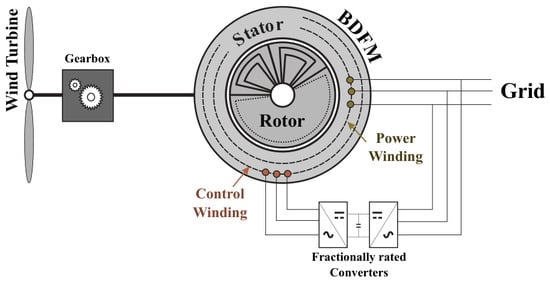
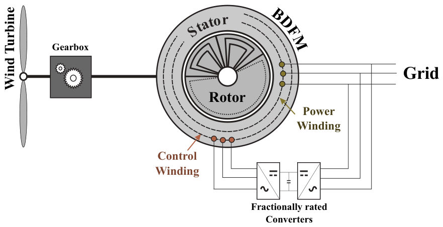
In WTs, BDFMs can be operated similarly to the widely used doubly fed induction generators [5]. The BDFM PWs are connected directly to the grid, while the CW is connected via fractionally rated power converters, as illustrated in Figure 1. They can also be operated across a wide speed range within sub-synchronous and super-synchronous regions while maintaining grid connections.
Figure 1.
Schematic illustration of a BDFM in a wind turbine.
The choice of BDFM / combinations is very important for performance. While studies about the best-performing pole-pair combinations continue to be published [13,23], a quick way to identify suitable combinations is by the determination of cross-coupling coefficients [24]. The / = 4/6 pole-pair combination, which operates at a natural speed of 300 rpm for a grid frequency of 50 Hz, exhibits relatively good performance [25,26].
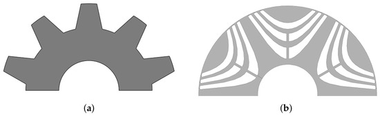
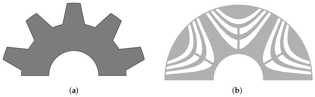
BDFM rotors may have windings or be reluctance rotors, with nests or poles equal to the number of + [12]. Although there are differential BDFMs with − rotor poles, their performances are typically inferior to the additive ( + ) BDFMs. The reluctance rotors can be salient pole or flux barrier rotors [16], as illustrated, respectively, in Figure 2.
Figure 2.
Semi-cross-sections of reluctance rotors: (a) salient pole and (b) flux barrier.
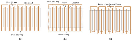
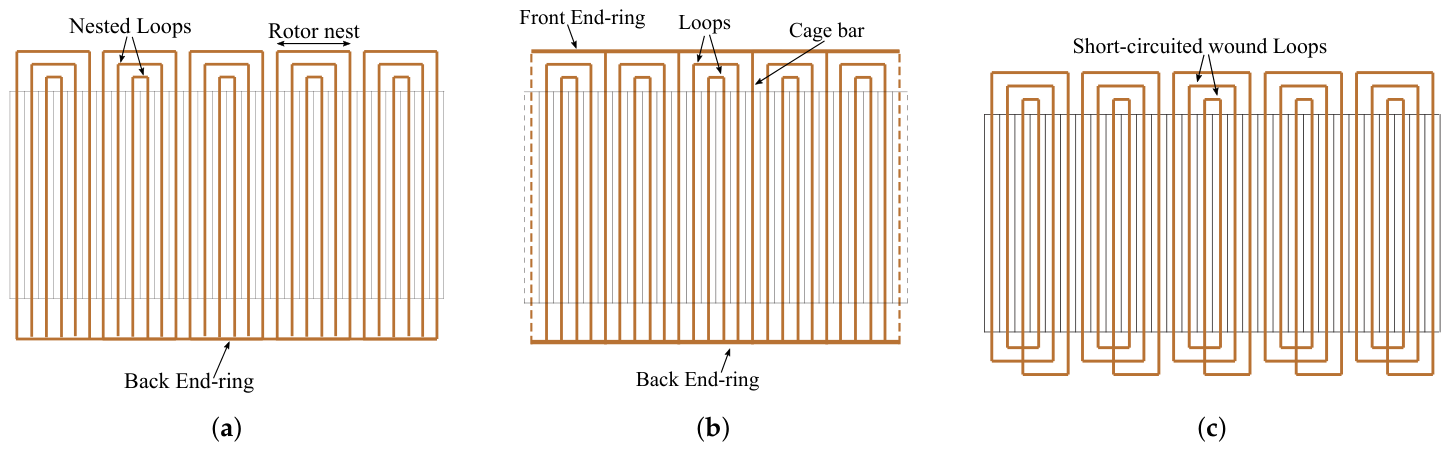
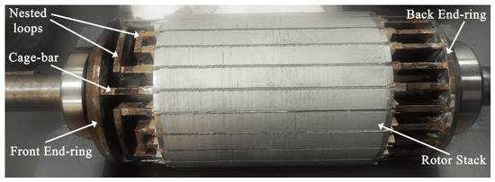
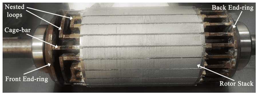
Popular rotor types with windings include nested loops (NLs), cage with nested loops (C-NL), and series wound rotors, with winding illustrations provided in Figure 3. The NL rotors comprise copper bars in laminated slots, which are connected in pairs to form loops. These loops are grouped together to form a number of + nests, as illustrated in Figure 3a. The C-NL rotor is similar to an NL rotor, save for the fact that the outer loops of each nest are replaced by a squirrel-cage-type winding with + bars, as illustrated in Figure 3b. In both NL and C-NL rotors, an end-ring is used to short-circuit all the bars at the back. In the series wound rotor, stranded copper conductors are wound in + nests according to the configuration illustrated in Figure 3c. Series wound rotors have greater series resistance, resulting in lower torque and higher copper losses compared to NL rotors [27]. Larger loop spans in NL and C-NL rotors are beneficial for torque production. Thus, the larger loop span of the C-NL cage facilitates a higher torque ceiling compared to the outer loops in NL rotors [28]. A C-NL rotor prototype is shown in Figure 4.
Figure 3.
BDFM rotor winding configurations: (a) nested loops, (b) cage with nested loops, and (c) series wound.
Figure 4.
Cage with nested-loop rotor prototype.
2.2. Wound-Field Flux-Switching Machines
Wound-field flux-switching machines (WFFSMs) are similar to switched reluctance machines with their doubly salient structures. However, WFFSMs have two windings on their stators: an AC armature winding and a DC field winding. While it is acknowledged that single-phase WFFSMs exist [21], the focus of this paper is on three-phase machines.
Similarly to BDFMs, three-phase armature windings in a WFFSM have a number of pole pairs (), which is different from the number of pole pairs in the field winding (). Since these two windings do not couple directly, their fluxes are also modulated by a special rotor, which is typically a salient pole rotor, as seen in Figure 2a. A conventional formula that shows the relationship between , , and the rotor poles () is given in [29] as
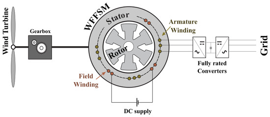
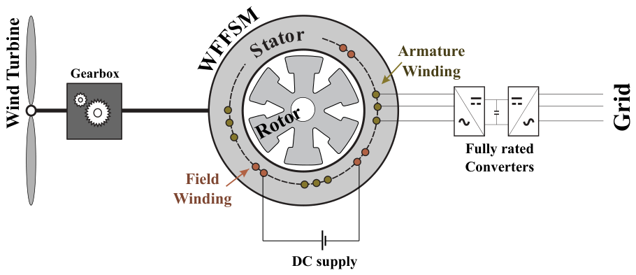
where i is an odd number. Although this formula is outlined for DC-excited vernier reluctance machines (DC-VRMs), WFFSMs operate under similar principles. Hence, WFFSMs are labeled as practically being DC-VRMs with overlapping windings in [30]. In a WT, WFFSMs will have their armature windings connected to a fully rated power converter, while their field windings are connected to DC sources. A schematic illustration of a WFFSM in a WT is given in Figure 5.
Figure 5.
Schematic illustration of a WFFSM in a WT.
The 24/10 WFFSM is a derivative of the 12/10 DC-VRM topology. The topology has relatively desirable characteristics, such as decent torque at a relatively high power factor, low core losses, symmetrical back-EMF, and a high overload capacity [29,30,31,32,33]. With 10 rotor poles, the 24/10 WFFSM coincidentally rotates at 300 rpm for a grid frequency of 50 Hz, similarly to the 4/6 BDFM. Upon closer inspection, the 24/10 WFFSM has significant similarities with a 4/6 BDFM. They both have main windings with four pole pairs; however, the 24/10 WFFSM armature winding consists of overlapping concentrated windings. Furthermore, both the 4/6 BDFM and the 24/10 WFFSM have secondary windings with six pole pairs. Nevertheless, the secondary/field winding of the WFFSM is an overlapping concentrated DC winding compared to the distributed AC winding of the 4/6 BDFM CW. Both the 4/6 BDFM and 24/10 WFFSM have 10 poles on their rotors.
It should be noted that the 24/10 WFFSM stator is closer to a predecessor of BDFMs called the Thompson motor, in which different windings occupy alternate segments [13]. On the other hand, although a 12/10 DC-VRM stator looks more like a contemporary BDFM, the radial force distribution is inferior to that of a 24/10 WFFSM, and this leads to extreme unwanted vibrations and performance deviations [34].
3. Method of Comparison
Although the wind turbine configurations for doubly fed induction generators (DFIGs) and synchronous generators are different, these topologies have been compared [5]. Seeing that BDFMs are viewed as an alternative to DFIGs, WFFSMs will be viewed contextually as alternatives to electrically excited synchronous generators. The method of comparison in this paper is to assess each brushless (flux modulation) topology with its closest electrically excited counterpart. The relative performance of the flux modulation (BDFM & WFFSM) topologies compared to their conventional (brushed) competitor is then used as the basis for performance description.
For comparisons, optimized designs of the 4/6 BDFM and 24/10 WFFSM topologies are acquired for the D400 machine’s frame size. The choice of frame size is not exactly arbitrary. To the best of the authors’ knowledge, the largest BDFM prototype built to date is based on this frame size [12,35]. The authors also have experience with a 12/10 DC-VRM prototype with the same frame size [34]. It should be recalled that a 24/10 WFFSM is basically a 12/10 DC-VRM with overlapping windings.
3.1. Optimization Process
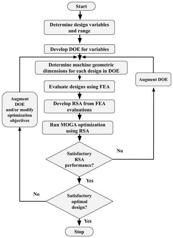
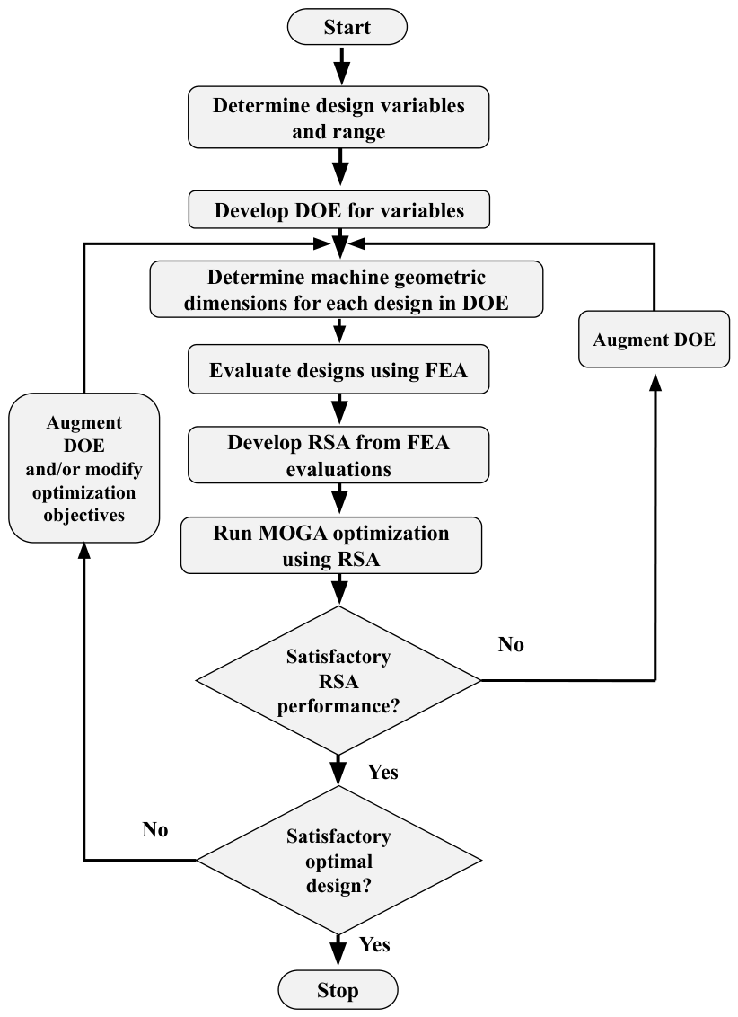
The optimization process involves the use of surrogate response surface approximations (RSAs) developed from finite-element analysis (FEA) of designs for either topology, as illustrated in Figure 6. This type of optimization is described in [36], and it provides a proactive and computationally efficient method to optimize machine designs, especially when dealing with lesser established topologies. Proactivity manifests with the designer actively inspecting the design space to identify areas of interest and design trends.
Figure 6.
Optimization flowchart.
Firstly, design variables are outlined. Then, a preliminary design of experiments (DOE) can be run with a small number of designs to determine the practical range of design variables. Latin hypercube sampling is used for DOEs due to the efficient mapping of the design space [36]. The DOEs and geometric designs of either topology are developed using Matlab R2020a. The geometric designs for the BDFMs are based on design developments presented in [37,38]. The approach to the WFFSM geometric designs is similar to that outlined in [39]. These designs are then adapted into FEA models of the topologies for evaluation in the ANSYS EDT 2024 R1 environment. A python script is used to coordinate the simulation runs and output data collection.
Transient 2-D time-stepping FEA models are used for all designs, and each design model is simulated at the maximum generating torque point. It is important to note that the main windings (PW for BDFM and armature winding for WFFSM) are modeled as voltage windings, while their secondary windings are modeled as current windings. The reason for this is because a current winding fixes the magnitude and phase shift of the current in a way that it is not affected by saturation and nonlinearities in inductances. Using current windings also assumes that the designer already knows the current produced, although this can vary significantly with changes in geometry. The Cogent M400-50A lamination steel material in ANSYS EDT 2024 R1 is used for all designs. End connections are considered for the power and armature windings because of the voltage excitations used. The formulas for calculating end-connection inductances and their contributions to the winding resistances were adapted from [40].
Output variables in Ansys EDT are used to determine the power factor and efficiency. The power factor is determined by transforming 3-phase voltages and currents into the d-q plane. Losses, including copper and core losses, are determined from the native ANSYS EDT results. The power generated () is calculated as
The surrogate (RSAs) and optimization models are developed using the response surface optimization module in ANSYS Workbench 2024 R1. The surrogate models are based on the Kriging method, developed using the earlier outlined DOE, while a multi-objective genetic algorithm (MOGA) is used for the optimization process. The convergence stability percentage for the optimizations is set at 2 %. A maximum number of 20 iterations is set, and the number of samples per iteration and initial population is 100.
3.2. Model Descriptions and Optimization Variables
To give a fair comparison, certain design parameters are fixed, as outlined in Table 1, for all evaluated topologies. The outer diameter () and stack length (l) are fixed for both topologies based on the measured dimensions of a D400 motor frame. The BDFM stators are designed with 72 slots, leading to a PW distribution of 3 slots per pole per phase and CW distribution of 2 slots per pole per phase. The number of stator slots is similar for 4/6 BDFMs designed in [23,25,41]. The WFFSM stator has 24 slots, and overlapping concentrated windings are used. While the 24/10 WFFSM rotor is a simple salient pole rotor with 10 poles, the rotor used for the 4/6 BDFM is a 50-slot C-NL rotor. The BDFM rotor has 50 slots; each nest contains 2 loops, and there are 10 bars that constitute the cage. A current density of 4 is used for the rotor bars. This is done to reduce the bar resistances and losses. Although the fill factor for squirrel cage rotors is typically close to 1 [40], a fill factor of 0.8 is used for the BDFM rotor bars. This lower fill factor is due to the need to insulate BDFM bars from steel cores to prevent interbar currents [42,43].
Table 1.
Fixed design parameters.
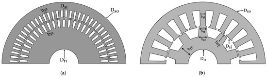
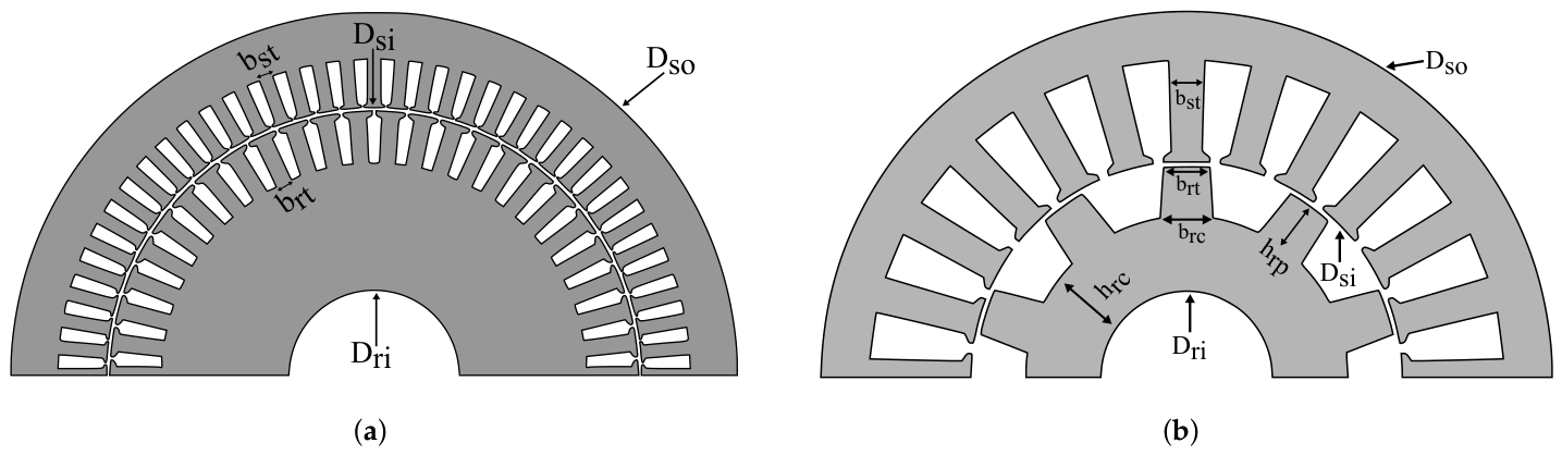
The variables considered for design optimization of the different topologies are listed in Table 2. Some of these variables are illustrated in Figure 7. The ranges for the number of turns per slot are based on the selected voltages. The tooth pitches are the proportion of the stator and rotor tooth widths ( & ) to their slot pitches. A large tooth pitch leads to lower teeth flux densities. However, given the constrained nature of the outer stator diameter, large teeth can lead to lower core depths. In the case of an unconstrained volume, larger tooth pitches generally lead to increases in machine size. The WFFSM rotor pole-to-core ratio () is the proportion of the rotor pole’s height () to the core’s depth (). A tapering factor () is used to size the bottom width of the WFFSM pole () as a proportion of , as tapering can help improve performances [44]. For the BDFM DOE, 1000 different design variations are considered, while 1400 design variations are used for the WFFSM DOE.
Table 2.
Optimization variables for the different topologies.
Figure 7.
Geometric illustrations: (a) 4/6 BDFM and (b) 24/10 WFFSM.
The considered optimization variables for the 20-pole DFIGs and EESMs are also listed in Table 2. A 20-pole DFIG rotates at a synchronous speed of 300 rpm for a 50 Hz grid frequency. Similarly, an EESM of 20 poles would operate at a speed of 300 rpm for the same frequency. Given the smaller number of design variables considered, the DFIG and EESM DOEs consist of only 180 designs each. The range for the inner stator diameter has a higher upper limit compared to the BDFMs and WFFSMs, because only the main windings are placed in the stator for conventional topologies. The stator and rotor teeth pitches are kept constant for the DFIG and EESM designs. Both DFIG and EESM topologies use designs with 180 stator slots and 120 rotor slots. This affords a distribution of 3 slots per pole per phase for their stator windings and 2 slots per pole per phase for the DFIG rotor winding. The EESM rotor winding is a single DC winding with 20 poles, resulting in a winding distribution of 6 slots per pole. An even split between the slot and teeth widths is applied for the DFIG and EESM designs. The fixed parameters listed in Table 1 are also fixed for the DFIG and EESM designs.
It is worth noting that the armature winding of the 24/10 WFFSM designs are excited with voltages at 67.5 Hz based on the speed of 405 rpm. In this study, 405 rpm is selected so that the 4/6 BDFM CW has a frequency of 17.5 Hz, which is at a slip of 0.35. The DFIGs are excited in a similar fashion as the BDFMs, and the EESMs are similar to the WFFSMs; both topologies are also operated at 405 rpm. The rms value of the rated BDFM/DFIG CW current is used as the rated field current for the WFFSM/EESM field winding. The current ratings for the main windings of the BDFMs and WFFSMs are calculated based on a maximum power rating of 125 kW, while the DFIGs’ and EESMs’ main winding currents are calculated based on a power rating of 250 kW.
4. Optimization Results
The optimization objective function for the BDFM and WFFSM topologies is to maximize the power generated within the constraints of efficiency and power factors. The optimization objective function () is defined as
where is the vector of the design variables for either topology. The constraints for the BDFMs () and WFFSMs (), placed based on observations from the DOE, are given as
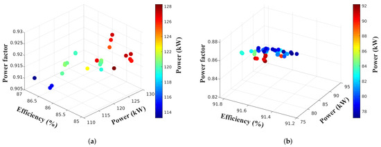
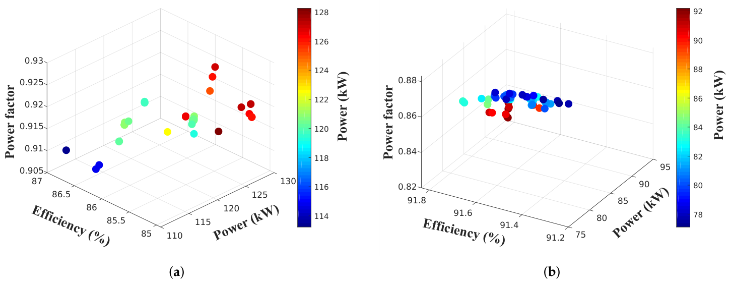
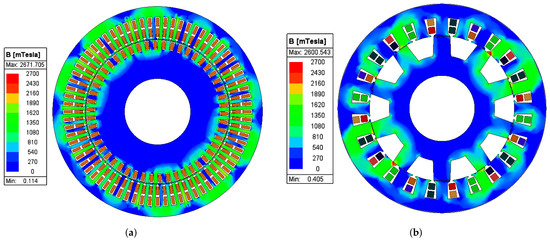
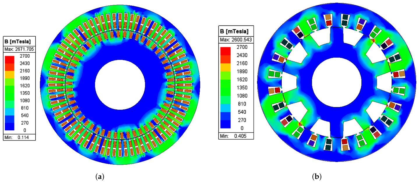
The selected optimal design variable combinations for the different topologies are listed side by side in Table 3. The output performances at peak generating torque and the generating unity power factor point from the designs developed from these variables are also listed in Table 3. The high-performing designs for the 4/6 BDFM and 24/10 WFFSM are illustrated using their peak generating torque performances in Figure 8. Note that all the performances are direct FEA outputs and not RSA-estimated performances.
Table 3.
Optimal design variables for different topologies.
Figure 8.
Possible optimal designs (a) 4/6 BDFM, (b) 24/10 WFFSM.
From Table 3 and Figure 8, the high-performing BDFM designs are capable of generating between 110 and 130 kW of power at their peak operating torque points. Their efficiencies are between 85 and 86.7%, with power factor values between 0.9 and 0.926. Specifically, at the peak generating torque point, the selected design highlighted in Table 3 generates about 121 kW at 86.4% efficiency with a power factor of 0.906. At the unity power factor point, the power generated drops to 111.5 kW at an increased efficiency of 87.3%.
The high-performing designs for the WFFSM topology generate peak power within the range of 77–92 kW. Their efficiencies are significantly higher than the BDFMs at about 91.4–91.8%, albeit with lower power factors in the range of 0.83–0.88. The selected WFFSM design generates about 92.3 kW at peak generating torque with an efficiency value and power factor of 91.7% and 0.83, respectively. At unity power factor, the selected WFFSM design generates 76.47 kW, which is significantly lower compared to the selected BDFM. This is as a result of the lower power factor at the peak torque point. However, the efficiency at unity power factor is very high at approximately 93%.
Comparing the selected BDFM design with the selected DFIG design, it can be determined that, at their peak generating torque points, the BDFM generates only about 58% power of the DFIG design. The DFIG also has a considerably higher efficiency and power factor of 91.9% and 0.93, respectively. Similarly, the selected WFFSM design only generates about 51.5% of the peak power generated by the selected EESM design. The peak torque power factor of the EESM is also significantly higher than that of the WFFSM. The steel masses of the BDFM and WFFSM designs are similar, just as the steel masses of the conventional machines are alike. The copper masses of the different designs are similar, except for the WFFSM, which is significantly lower due to the concentrated windings used.
The FEA models for the BDFM and WFFSM designs operating at their peak generating torque points are illustrated in Figure 9 with flux density overlays. There is no widespread saturation in the machine parts, so neither design is compromised. The load levels are controlled by reducing the exciting CW and field currents for the BDFM and WFFSM designs, respectively, with performances outlined in Table 4. The efficiencies of both the BDFM and WFFSM increase at 50% excitation compared to the full load. However, their power factors drop predictably. At 30% excitation, the BDFM efficiency further increases while the WFFSM efficiency drops, with further reductions in the power factor for both topologies.
Figure 9.
Optimal designs: (a) 4/6 BDFM and (b) 24/10 WFFSM.
Table 4.
BDFM and WFFSM design performance at different excitation levels.
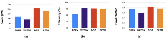
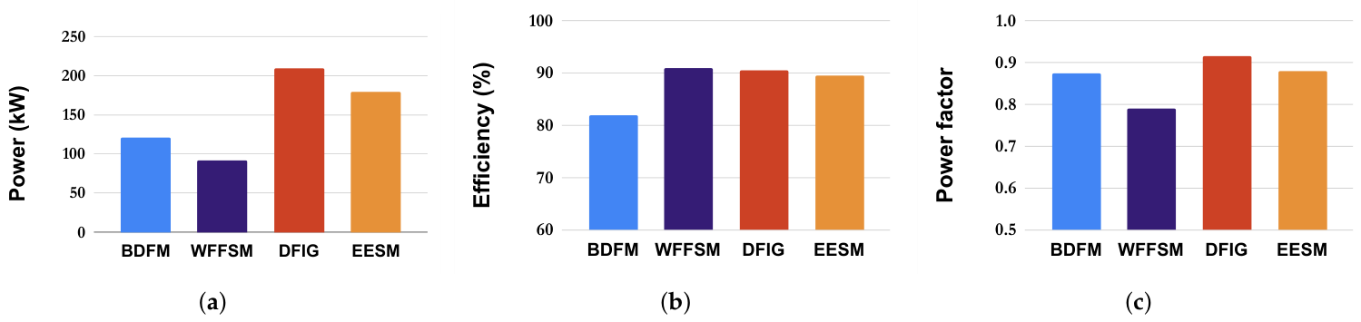
A summary of the performances of different topologies is illustrated in Figure 10. For the given machine frame, the 4/6 BDFM and 24/10 WFFSM generate a similar amount of peak power. The efficiency of the WFFSM is significantly higher than the BDFM, while the BDFM power factor is noticeably higher than that of the WFFSM. The conventional topologies that use brushes (DFIG & EESM) have significantly higher power densities (power per volume) than their (brushless) flux-modulating counterparts.
Figure 10.
Performance charts for selected designs at peak generating torque: (a) power generated and (b) efficiency, and (c) power factor.
5. Discussion
It is a bit difficult to compare the exact limits of excitation applied for both flux modulation topologies. Whereas the control/secondary windings of BDFMs are distributed three-phase AC windings, the secondary/field windings of WFFSMs are concentrated multipole DC windings. This is why it is important to view the performances of the flux modulation machines with respect to a similar conventional topology.
Both topologies exhibit deficiencies in power density compared to conventional topologies like DFIGs and EESMs. Similar inefficiencies in flux utilization by the cross-coupling process in BDFMs is observable in WFFSMs. Furthermore, flux from both windings on the stator of flux-modulating machines pass through similar flux paths, leading to higher levels of saturation. Thus, they have lower excitation limits compared to conventional machines. Increasing the CW or field currents excessively yields diminishing returns with reduced power factors.
Power converters are usually sized based on apparent power, and WFFSMs would require fully rated converters in WTs. The low power factor in the WFFSM means that the power converter would likely be rated higher than the real power generated. Also, the values highlighted at unity power factor provide context for the seemingly oversized BDFMs. In WTs, grid codes require DFIGs be operated between 0.95 lagging and leading power factors [45]. BDFMs would necessarily be required to operate within such requirements, for which the unity power factor region is in between. Although designs with greater generated power are present in the BDFM DOE, they have lower power factors. Thus, at a rated CW current, the designs with higher torque will generate lower power and potentially require larger power converters for operations at required power factor levels. Similarly, designs with higher power can be obtained from the WFFSM DOE, but these will have even lower power factors.
The field and armature turns in a WFFSM occupy separate slots, which leads to under-utilization of the slot space, as the field coils are larger. The stator slots in a 12/10 DC-VRM are shared by both armature and field coils, leading to potentially better space utilization. However, the radial forces in a 12/10 DC-VRM are not well distributed, leading to excessive vibrations [34]. Conventional topologies have their primary windings in their stators; thus, the inner stator diameters are larger, and this helps with greater torque production.
6. Conclusions
In this paper, the relative power densities of two of the most widely researched electrically excited flux modulation machine topologies (BDFMs and WFFSMs) have been evaluated and categorized. To this end, the 4/6 BDFM and 24/10 WFFSM were selected for comparison due to their similarities in pole combinations. Also, both selected BDFM and WFFSM configurations are well noted in the literature due to their desirable performances. Optimized designs were obtained for both topologies at the same operating speed and within a D400 machine frame.
It is shown that there is no significant difference in power generated within a given volume between the flux-modulating topologies compared to the difference in power relative to conventional topologies. Both topologies have lower power densities and power factors compared to DFIGs and EESMs. The WFFSMs have superior efficiency afforded by their concentrated windings and passive rotors, whereas the C-NL rotor used for the BDFM has conductors that produce extra copper losses. Despite this, the BDFM has a higher power factor compared to the WFFSM. To increase the power obtained in a given machine volume, a focus on the double-stator configurations of BDFMs and WFFSMs is beneficial. With double-stator configurations, the inactive volume noticeable in the blue overlaid rotor cores in Figure 9 can be more efficiently utilized. Also, some design insights are transferable between BDFMs and WFFSMs, especially when pole-pair combinations are similar.
For grid-connected brushless operations, BDFMs are perhaps preferable, as they require lower-rated converters due to higher power factor and wider speed range. The wider speed range is due to the fact that a WFFSM requires a fully rated converter regardless of the operating speed. However, the efficiency of BDFMs is relatively low. In this regard, comparisons can also be made using BDFMs with reluctance rotors, although a drop in power factor is anticipated. For direct-drive applications, slower BDFMs will be required, which will necessitate having even more slots, thereby complicating the machine’s construction. WFFSMs have much simpler constructions, as the operational frequencies can easily be adjusted to suit the required speed.
Author Contributions
Conceptualization, O.I.O.; formal analysis, O.I.O.; funding acquisition, U.B.A.; investigation, O.I.O. and U.B.A.; project administration, U.B.A., T.O.O. and P.Z.S.; software, O.I.O. and U.B.A., supervision: U.B.A., T.O.O. and P.Z.S.; validation, O.I.O., U.B.A., T.O.O. and P.Z.S.; visualization, O.I.O., writing—original draft: O.I.O.; writing—review and editing, U.B.A., T.O.O. and P.Z.S. All authors have read and agreed to the published version of this manuscript.
Funding
This work was conducted under the Circular Economy Powered Renewable Energy Centre (CEPREC) and supported by the UK Government’s Ayrton Fund and the International Science Partnerships Fund (ISPF) awarded by UK Research and Innovation (UKRI) under grant UKRI/EP/B000320/1.
Institutional Review Board Statement
Not applicable.
Informed Consent Statement
Not applicable.
Data Availability Statement
The data presented in this study are available upon request from the corresponding author due to technical constraints regarding public repository storage.
Acknowledgments
O. I. Olubamiwa acknowledges the support of the Tshwane University of Technology.
Conflicts of Interest
The authors declare no conflicts of interest. The funders had no role in the design of the study; the collection, analysis, or interpretation of data; the writing of the manuscript; or the decision to publish the results.
Abbreviations
The following abbreviations are used in this manuscript:
| Acronyms | ||
| AC | Alternating current | |
| BDFM | Brushless doubly fed machine | |
| CW | Control winding | |
| DC | Direct current | |
| DC-VRM | DC-excited vernier reluctance machine | |
| DOE | Design of experiment | |
| DFIG | Doubly fed induction generator | |
| EESM | Electrically excited synchronous motor | |
| FEA | Finite-element analysis | |
| PM | Permanent magnet | |
| PW | Power winding | |
| RSA | Response surface approximation/surrogate model | |
| WFFSM | Wound-field flux-switching machine | |
| WT | Wind turbine | |
| Design parameters | ||
| Rotor tooth width | ||
| Stator tooth width | ||
| Shaft diameter | mm | |
| Stator inner diameter | mm | |
| Stator outer diameter | mm | |
| g | air-gap length | mm |
| Rotor pole to core ratio | ||
| Tapering factor | ||
| l | Stack length | mm |
| Primary winding turns per slot | ||
| Secondary winding turns per slot | ||
| Number of rotor slots/poles | ||
| BDFM PW pole pairs | ||
| BDFM CW pole pairs | ||
| WFFSM armature pole pairs | ||
| WFFSM field pole pairs | ||
| Rotor tooth/pole pitch | ||
| stator pole pitch | ||
| Electromagnetic and mechanical parameters | ||
| Secondary winding (phase) current | A | |
| Rotor mechanical speed | rpm | |
| Power generated | kW | |
| Primary winding phase voltage | V | |
References
- Global Wind Energy Council. Global Wind Report 2025; Technical Report; GWEC: Brussels, Belgium, 2025. [Google Scholar]
- Díaz, H.; Guedes Soares, C. Review of the current status, technology and future trends of offshore wind farms. Ocean Eng. 2020, 209, 107381. [Google Scholar] [CrossRef] [Scilit]
- Carroll, J.; McDonald, A.; Dinwoodie, I.; McMillan, D.; Revie, M.; Lazakis, I. Availability, operation and maintenance costs of offshore wind turbines with different drive train configurations. Wind Energy 2017, 20, 361–378. [Google Scholar] [CrossRef] [Scilit]
- Sethuraman, L.; Maness, M.; Dykes, K. Optimized Generator Designs for the DTU 10-MW Offshore Wind Turbine Using GeneratorSE: Preprint; National Renewable Energy Laboratory (NREL): Golden, CO, USA, 2017; p. 1. [CrossRef] [Scilit]
- Chen, H.; Zuo, Y.; Chau, K.T.; Zhao, W.; Lee, C.H.T. Modern electric machines and drives for wind power generation: A review of opportunities and challenges. IET Renew. Power Gener. 2021, 15, 1864–1887. [Google Scholar] [CrossRef] [Scilit]
- Carroll, J.; McDonald, A.; McMillan, D. Reliability Comparison of Wind Turbines With DFIG and PMG Drive Trains. IEEE Trans. Energy Convers. 2015, 30, 663–670. [Google Scholar] [CrossRef] [Scilit]
- Dong, Z.; Jiang, M.; Niu, S.; Chau, K. Overview of permanent magnet wind power generators. IEEE Trans. Magn. 2025, 61, 8102011. [Google Scholar] [CrossRef] [Scilit]
- Gyftakis, K.N.; Skarmoutsos, G.A.; Barajas-Solano, I.; Burchell, J.; Mueller, M. Critical Aspects of Demagnetization Faults in Multi-Stage Direct Drive Permanent Magnet Generators for Renewables. IEEE Trans. Ind. Appl. 2023, 59, 6655–6663. [Google Scholar] [CrossRef] [Scilit]
- Zhu, X.; Lee, C.H.T.; Chan, C.C.; Xu, L.; Zhao, W. Overview of Flux-Modulation Machines Based on Flux-Modulation Principle: Topology, Theory, and Development Prospects. IEEE Trans. Transp. Electrif. 2020, 6, 612–624. [Google Scholar] [CrossRef] [Scilit]
- Li, D.; Qu, R.; Li, J. Topologies and analysis of flux-modulation machines. In Proceedings of the 2015 IEEE Energy Conversion Congress and Exposition (ECCE), Montreal, QC, Canada, 20–24 September 2015; pp. 2153–2160. [Google Scholar] [CrossRef] [Scilit]
- McMahon, R.A.; Roberts, P.C.; Wang, X.; Tavner, P.J. Performance of BDFM as generator and motor. IEE Proc.-Electr. Power Appl. 2006, 153, 289–299. [Google Scholar] [CrossRef] [Scilit]
- Strous, T.D.; Polinder, H.; Ferreira, J.A. Brushless doubly-fed induction machines for wind turbines: Developments and research challenges. IET Electr. Power Appl. 2017, 11, 991–1000. [Google Scholar] [CrossRef] [Scilit]
- Olubamiwa, O.I.; Gule, N. A Review of the Advancements in the Design of Brushless Doubly Fed Machines. Energies 2022, 15, 725. [Google Scholar] [CrossRef] [Scilit]
- Liu, Y.; Hussien, M.G.; Xu, W.; Shao, S.; Rashad, E.M. Recent Advances of Control Technologies for Brushless Doubly-Fed Generators. IEEE Access 2021, 9, 123324–123347. [Google Scholar] [CrossRef] [Scilit]
- Han, P.; Cheng, M.; Ademi, S.; Jovanovic, M.G. Brushless doubly-fed machines: Opportunities and challenges. Chin. J. Electr. Eng. 2018, 4, 1–17. [Google Scholar] [CrossRef] [Scilit]
- Sadeghian, O.; Tohidi, S.; Mohammadi-Ivatloo, B.; Mohammadi, F. A Comprehensive Review on Brushless Doubly-Fed Reluctance Machine. Sustainability 2021, 13, 842. [Google Scholar] [CrossRef] [Scilit]
- Lee, C.H.T.; Chau, K.T.; Liu, C.; Chan, C.C. Overview of magnetless brushless machines. IET Electr. Power Appl. 2018, 12, 1117–1125. [Google Scholar] [CrossRef] [Scilit]
- Zhou, Y.J.; Zhu, Z.Q. Comparison of Wound-Field Switched-Flux Machines. IEEE Trans. Ind. Appl. 2014, 50, 3314–3324. [Google Scholar] [CrossRef] [Scilit]
- Sulaiman, E.B.; Kosaka, T.; Matsui, N. Design study and experimental analysis of wound field flux switching motor for HEV applications. In Proceedings of the 2012 XXth International Conference on Electrical Machines, Marseille, France, 2–5 September 2012; pp. 1269–1275. [Google Scholar] [CrossRef] [Scilit]
- Cao, R.; Yuan, X.; Jin, Y.; Zhang, Z. MW-Class Stator Wound Field Flux-Switching Motor for Semidirect Drive Wind Power Generation System. IEEE Trans. Ind. Electron. 2019, 66, 795–805. [Google Scholar] [CrossRef] [Scilit]
- Khan, F.; Sulaiman, E.; Ahmad, M.Z. Review of switched flux wound-field machines technology. IETE Tech. Rev. 2017, 34, 343–352. [Google Scholar] [CrossRef] [Scilit]
- Abunike, C.E.; Okoro, O.I.; Far, A.J.; Aphale, S.S. Advancements in flux switching machine optimization: Applications and future prospects. IEEE Access 2023, 11, 110910–110942. [Google Scholar] [CrossRef] [Scilit]
- Oraee, A.; McMahon, R.; Abdi, E.; Abdi, S.; Ademi, S. Influence of Pole-pair Combinations on the Characteristics of the Brushless Doubly Fed Induction Generator. IEEE Trans. Energy Convers. 2020, 35, 1151–1159. [Google Scholar] [CrossRef] [Scilit]
- Mahmoud, F.; Hussain, H. Investigating the Effects of Iron Ribs in Brushless Doubly Fed Reluctance Machine. In Proceedings of the 2024 IEEE Energy Conversion Congress and Exposition (ECCE), Phoenix, Arizona, 20–24 October 2024; p. 5143. [Google Scholar] [CrossRef] [Scilit]
- Wang, X.; Polinder, H.; Lahaye, D.; Ferreira, J.A. FE based multi-objective optimization of a 3.2 MW brushless doubly-fed induction machine. In Proceedings of the 2017 IEEE Workshop on Electrical Machines Design, Control and Diagnosis (WEMDCD), Nottingham, UK, 20–21 April 2017; pp. 89–94. [Google Scholar] [CrossRef] [Scilit]
- Olubamiwa, O.I.; Gule, N. Relative performances of pole pair combinations for Brushless Doubly fed Machines. In Proceedings of the 2023 IEEE International Electric Machines & Drives Conference (IEMDC), San Francisco, CA, USA, 15–18 May 2023; pp. 1–7. [Google Scholar] [CrossRef] [Scilit]
- Mcmahon, R.; Tavner, P.; Abdi, E.; Malliband, P.; Barker, D. Characterising brushless doubly fed machine rotors. IET Electr. Power Appl. 2013, 7, 535–543. [Google Scholar] [CrossRef] [Scilit]
- Logan, T.G.; McMahon, R.A.; Tavner, P.J.; Tohidi, S. A comparison of cage and nested-loop BDFM rotors. In Proceedings of the 6th IET International Conference on Power Electronics, Machines and Drives (PEMD 2012), Bristol, UK, 27–29 March 2012; pp. 1–6. [Google Scholar] [CrossRef] [Scilit]
- Jia, S.; Qu, R.; Li, J.; Li, D.; Lu, H. Design Considerations of Stator DC-Winding Excited Vernier Reluctance Machines Based on the Magnetic Gear Effect. IEEE Trans. Ind. Appl. 2017, 53, 1028–1037. [Google Scholar] [CrossRef] [Scilit]
- Jia, S.; Qu, R.; Li, J.; Li, D. Principles of Stator DC Winding Excited Vernier Reluctance Machines. IEEE Trans. Energy Convers. 2016, 31, 935–946. [Google Scholar] [CrossRef] [Scilit]
- Akuru, U.B.; Mabhula, M.; Kamper, M.J. On the Electromagnetic Performance Prediction of Turbo Synchronous Condensers Based on Wound-Field Flux Switching Machine Design. IEEE Trans. Ind. Appl. 2021, 57, 3687–3698. [Google Scholar] [CrossRef] [Scilit]
- Jia, S.; Qu, R.; Li, J.; Chen, Y. Comparison of stator DC-excited vernier reluctance machines with synchronous reluctance machines. In Proceedings of the 2015 IEEE International Electric Machines & Drives Conference (IEMDC), Coeur d’Alene, ID, USA, 10–13 May 2015; pp. 649–655. [Google Scholar] [CrossRef] [Scilit]
- Jia, S.; Qu, R.; Li, J. Analysis of the Power Factor of Stator DC-Excited Vernier Reluctance Machines. IEEE Trans. Magn. 2015, 51, 8207704. [Google Scholar] [CrossRef] [Scilit]
- Olubamiwa, O.I.; Botha, S.; McIntyre, S.C.; Kamper, M.J. The Viability of DC-VRM Synchronous Condensers. IEEE Trans. Energy Convers. 2025, 41, 1480–1490. [Google Scholar] [CrossRef] [Scilit]
- Abdi, E.; Mcmahon, R.; Malliband, P.; Shao, S.; Mathekga, M.E.; Tavner, P.; Abdi, S.; Oraee, A.; Long, T.; Tatlow, M. Performance analysis and testing of a 250 kW medium-speed brushless doubly-fed induction generator. IET Renew. Power Gener. 2013, 7, 631–638. [Google Scholar] [CrossRef] [Scilit]
- Bramerdorfer, G.; Tapia, J.A.; Pyrhönen, J.J.; Cavagnino, A. Modern Electrical Machine Design Optimization: Techniques, Trends, and Best Practices. IEEE Trans. Ind. Electron. 2018, 65, 7672–7684. [Google Scholar] [CrossRef] [Scilit]
- McMahon, R.A.; Mathekga, M.E.; Wang, X.; Tatlow, M.R. Design considerations for the brushless doubly-fed (induction) machine. IET Electr. Power Appl. 2016, 10, 394–402. [Google Scholar] [CrossRef] [Scilit]
- Olubamiwa, O.I.; Gule, N. Design and optimization of a Cage + Nested loops rotor BDFM. In Proceedings of the 2020 International Conference on Electrical Machines (ICEM), Gothenburg, Sweden, 23–26 August 2020; Volume 1, pp. 1868–1874. [Google Scholar] [CrossRef] [Scilit]
- Mngomezulu, Z.S.; Olubamiwa, O.I.; Akuru, U.B.; Popoola, O.M. Performance Assessment of a Double-Stator Wound-Field Flux-Switching Machine for Large-Scale Direct-Drive Wind Power Generator Applications. Wind 2026, 6, 26. [Google Scholar] [CrossRef] [Scilit]
- Boldea, I.; Nasar, S. The Induction Machines Design Handbook, 2nd ed.; Electric Power Engineering Series; Taylor & Francis: Boca Raton, FL, USA, 2009. [Google Scholar]
- Strous, T.D.; Wang, X.; Polinder, H.; Ferreira, J.A.B. Finite element based multi-objective optimization of a brushless Doubly-Fed Induction Machine. In Proceedings of the 2015 IEEE International Electric Machines Drives Conference (IEMDC), Coeur d’Alene, ID, USA, 10–13 May 2015; pp. 1689–1694. [Google Scholar] [CrossRef] [Scilit]
- Williamson, S.; Boger, M.S. Impact of inter-bar currents on the performance of the brushless doubly fed motor. IEEE Trans. Ind. Appl. 1999, 35, 453–460. [Google Scholar] [CrossRef] [Scilit]
- Roberts, P.C. A Study of Brushless Doubly-Fed (Induction) Machines. Ph.D. Thesis, University of Cambridge, Cambridge, UK, 2004. [Google Scholar]
- Dippenaar, J.; Kamper, M.J. Simple Robust Rotor 5 MW Synchronous Reluctance Generator. In Proceedings of the 2020 IEEE Energy Conversion Congress and Exposition (ECCE), Detroit, MI, USA, 11–15 October 2020; pp. 1426–1432. [Google Scholar] [CrossRef] [Scilit]
- Abad, G.; López, J.; Rodríguez, M.; Marroyo, L.; Iwanski, G. Doubly Fed Induction Machine: Modeling and Control for Wind Energy Generation; IEEE Press Series on Power Engineering; Wiley: Hoboken, NJ, USA, 2011. [Google Scholar]

Disclaimer/Publisher’s Note: The statements, opinions and data contained in all publications are solely those of the individual author(s) and contributor(s) and not of MDPI and/or the editor(s). MDPI and/or the editor(s) disclaim responsibility for any injury to people or property resulting from any ideas, methods, instructions or products referred to in the content. |
© 2026 by the authors. Licensee MDPI, Basel, Switzerland. This article is an open access article distributed under the terms and conditions of the Creative Commons Attribution (CC BY) license.