


Abstract
Standalone solar chemical heat pumps (SCHPs) have attracted increasing attention as promising technologies for utilizing renewable solar thermal energy for heating and cooling applications. However, residential deployment remains challenging because reducing collector area and installation space generally leads to a decline in thermochemical storage performance. In particular, practical design guidelines for minimizing system size while maintaining performance under moderate solar irradiation conditions such as in autumn have not been sufficiently established. In this study, a standalone CaSO4 solar chemical heat pump driven solely by solar thermal energy and a photovoltaic-powered heat exchange medium (HEM) circulation system was experimentally investigated. First, the influence of HEM flow rate on sensible and thermochemical heat storage was evaluated using a baseline configuration equipped with two solar collectors. Subsequently, the collector area was reduced by employing a single collector. Finally, the apparatus layout was optimized through adjustment of the collector tilt angle for autumn operation in Japan and reduction in piping length by vertically installing the CHP unit. The results showed that increasing the HEM flow rate enhanced heat transfer and promoted the dehydration reaction of CaSO4. Under the optimum condition, a conversion of approximately 93% and a chemical heat storage capacity of 537 kJ were achieved. Furthermore, the optimized layout significantly reduced thermal losses and improved solar energy utilization. Although the collector area was reduced by 50%, the optimized Type 3 configuration achieved a chemical heat storage capacity of 462 kJ, corresponding to 84% of that of the baseline system. In other words, a 50% reduction in collector area resulted in only a 16% reduction in heat storage capacity. These results demonstrate that system-level optimization can substantially mitigate the performance loss associated with collector downsizing. The proposed configuration provides a practical pathway toward compact residential SCHPs with reduced installation space requirements while maintaining high thermochemical heat storage performance.
1. Introduction
Chemical heat pumps (CHPs) can store thermal energy in the form of chemical energy via an endothermic reaction and release it at various temperature levels as cold/hot heat during the heat demand period via endothermic and exothermic reactions. CHPs do not need electric power because they can be driven by thermal energy. They also have several advantages, such as high energy density and long-term thermal storage, that are generally unavailable in conventional absorption and adsorption heat pumps [1]. Various heat storage materials have been proposed for CHPs depending on their operating temperature ranges. For instance, in inorganic systems, CaCl2 systems are suitable for low-temperature ranges below 353 K, CaSO4 systems for 373 K, MgO systems for 573 K, and CaO systems for 673 K. In organic systems, Krishnados et al. [2] conducted a numerical investigation of a CHP using alcohol and ketones at a range of 373–473 K.
Although photovoltaic modules have recently achieved conversion efficiencies exceeding 23% [3], solar thermal collectors can typically utilize 40–80% of the incident solar energy as useful heat. Assuming a PV module efficiency of 23% and an electrically driven vapor-compression heat pump with a COP of five, the overall solar-to-thermal conversion factor becomes approximately 1.15. By comparison, a solar thermal evacuated-tube collector with an efficiency of 80% can directly deliver hot heat with a solar-to-thermal factor of 0.8 without using any expensive heat pumps. Coupling with thermally driven chemical heat pumps, such as the CaSO4 system presented in this study (thermal COP = 1.63), yields an overall solar-to-thermal efficiency of approximately 1.30 for cold/hot heat release. Consequently, solar thermal systems can achieve the same heating/cooling output with a smaller collector area than PV-driven heat pump systems. Moreover, solar thermal collector systems are generally less expensive than PV module systems, resulting in potential reductions in system cost.
CHPs using solar thermal energy are called solar chemical heat pumps (SCHPs). Solar thermal energy has long been utilized for domestic water-heating applications. However, by combining solar thermal energy with CHPs, it can be used for air conditioners. Considerable research has been conducted on solar-driven absorption and adsorption heat pumps for cooling applications [4,5]. Following that, research on SCHPs has been conducted with various heat storage materials. Fadhel et al. [6] investigated a heat pump dryer utilizing a CaCl2 system in tropical regions for drying agricultural and marine products. Additionally, simulations of the coefficient of performance for an SCHP under Malaysian meteorological conditions were performed [7]. The underpinning chemical heat pump (CHP) can be configured with different reaction pairs to match temperature grades: Wang et al. [8] utilized a MgO system as an auxiliary heat source and for steam cooling in a turbine power generation system using direct steam generation collectors. Zhang et al. [9] investigated a CaO system to improve the efficiency of concentrated solar power systems.
For residential applications, the available solar thermal energy is typically around 373 K because water is commonly used as the heat exchange medium. Flat-plate solar collectors typically operate with thermal efficiencies of 40–70% at temperatures below approximately 80 °C, whereas evacuated-tube collectors equipped with CPC reflectors can maintain thermal efficiencies of 50–80% over a wider temperature range extending beyond 373 K [10].
Therefore, gypsum (CaSO4∙2H2O) is suitable for this application because the CaSO4∙1/2H2O/CaSO4 endothermic reaction proceeds at approximately 373 K, and gypsum is also readily available, non-toxic and easy to handle. For these reasons, gypsum has attracted increasing attention as a thermochemical energy storage material [11]. For example, a solar heat amount QH,S of (241 kJ/kg-CaSO4, 217 MJ/m3-CaSO4) is chemically stored, and 423 K high-temperature heat QH,R (241 kJ/kg-CaSO4, 217 MJ/m3-CaSO4) and 253 K low-temperature heat QL,R (153 kJ/kg-CaSO4, 138 MJ/m3-CaSO4) are released in the heat demand period by the CaSO4 CHP system. These values are not so high compared with those of some other thermochemical storage systems, but much higher than sensible/latent heat storage systems.
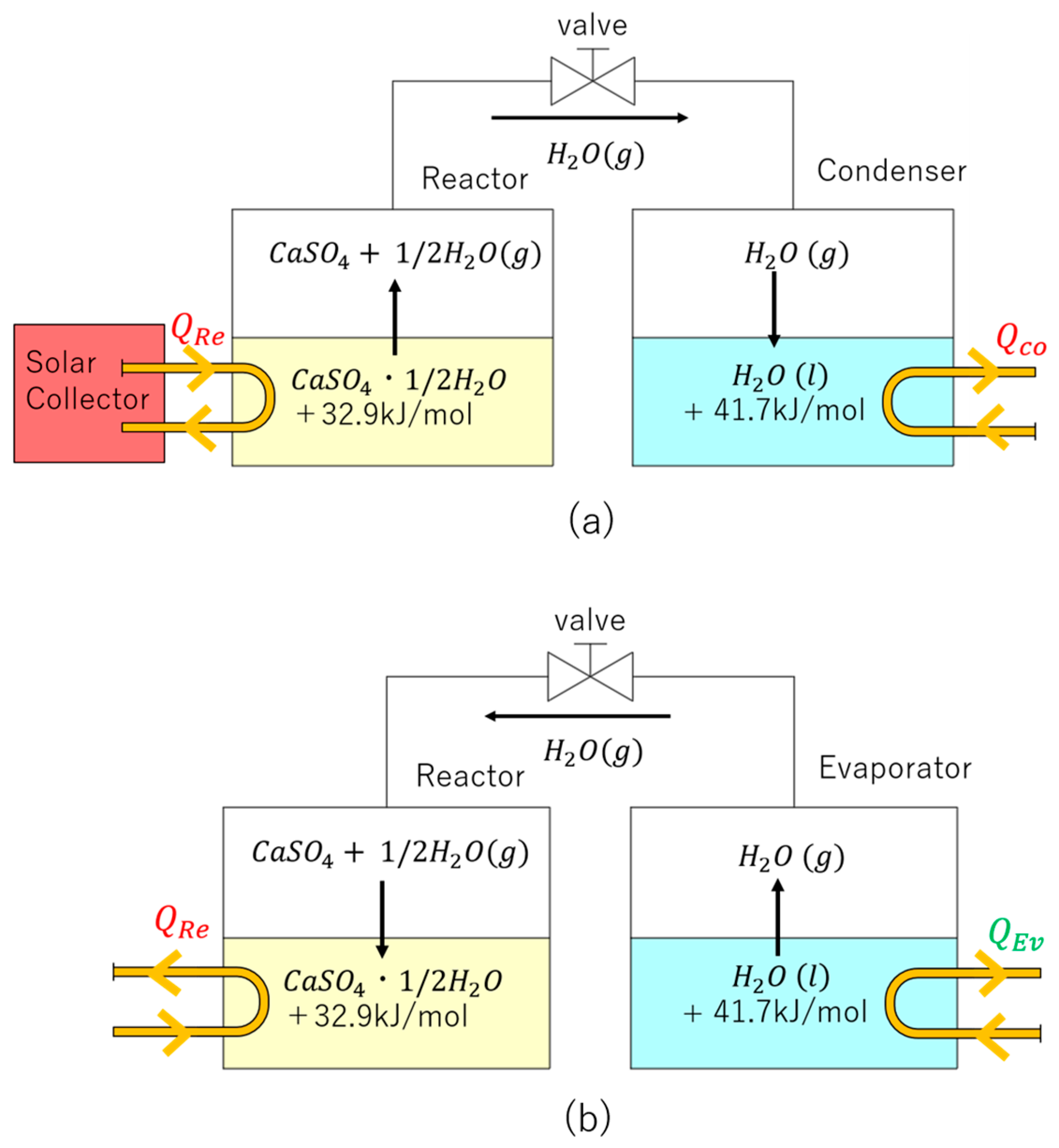
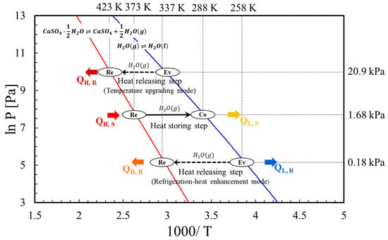
Figure 1 depicts a schematic diagram of the heat storing (a) and heat releasing (b) steps of SCHP using the CaSO4/H2O reaction. Figure 2 illustrates the operations on the equilibrium line of the SCHP system. As Figure 1a shows, the CHP subsystem comprises two tanks, a reactor (Re) and a condenser/evaporator (Co/Ev). The latter tank acts as a condenser (Co) in the heat storing step to condense water vapor, and acts as an evaporator (Ev) in the heat releasing step to evaporate water vapor. The Re containing reactant and Co/Ev containing the ethylene glycol aqueous solution as the condensing/evaporating solution are connected by a joint valve to control gas passage (like water vapor) [12]. Since ethylene glycol is an antifreeze, the experiment can be conducted smoothly without solidification, even if the temperature drops below 273 K. The reversible chemical reaction equation in the CHP subsystem is given by
Figure 1.
Schematic diagram of solar chemical heat pump (SCHP): (a) heat storing step; (b) heat releasing step.
Figure 2.
Operations on equilibrium line of SCHP system.
In the Re:
CaSO4∙1/2H2O(s) + 32.9 kJ/mol ⇌ CaSO4(s) + 1/2H2O(g)
In the Co/Ev:
H2O(g) ⇌ H2O(l) + 41.7 kJ/mol
As also shown in Figure 2, the detailed description of the synergy between the Re and the Co/Ev is shown below.
In the heat storing step, as shown in Figure 1a, when the sunlight irradiates the solar collector (SC), the temperature of the heat exchange medium (HEM) in the SC is increased. The reactant temperature in the Re rises through the HEM. When the reactant temperature reaches the required chemical heat storage conditions (e.g., 373 K, 1.68 kPa), the dehydration reaction occurs. The reactant CaSO4∙1/2H2O is dehydrated into CaSO4. QH,S (241 kJ/kg CaSO4, 217 MJ/m3 CaSO4) is stored as thermochemical energy in the Re in the heat storing step, which is a permanent chemical heat with almost no loss. Since water vapor is generated due to the dehydration reaction, the water vapor moves to the Co due to the pressure difference and condenses into water by heat exchange in the Co. The joint valve closes when the dehydration reaction is close to the end. At this time, the condensation heat QL,S (153 kJ/kg CaSO4, 138 MJ/m CaSO4) of water vapor is stored at the condensation equilibrium temperature (e.g., 288 K, 1.68 kPa).
In the heat releasing step, when the joint valve is opened, water evaporates into water vapor. The water vapor moves from the Ev to Re, and when it arrives at the Re, CaSO4.∙1/2H2O is generated by the hydration reaction of CaSO4. High-temperature heat QH,R (241 kJ/kg CaSO4, 217 MJ/m3 CaSO4) is generated in the Re, and low-temperature heat QL,R (153 kJ/kg CaSO4, 138 MJ/m CaSO4) is produced in the Ev. For example, there are two modes presented in Figure 2. In the temperature upgrading mode, the hot heat QH,R (e.g., 423 K) in the Re can be released under the evaporation equilibrium pressure (e.g., 20.9 kPa). In the refrigeration-heat enhancement mode, the hot heat QH,R (e.g., 337 K) in the Re and the cold heat (e.g., 258 K) in the Ev can be released under the evaporation equilibrium pressure (e.g., 0.18 kPa). In this case, the thermal efficiency (thermal COP) for cold/hot heat generation comes to 1.63.
Calorimetric and kinetic studies on the exothermic and endothermic reactions of gypsum were conducted and the enhancement of chemical heat storage performance was investigated [13,14].
The reaction kinetics of the CaSO4/CaSO4∙1/2H2O system have previously been investigated by our group, and the following rate equations were proposed [15]. As the detailed reaction kinetics have already been discussed in that study, only a brief summary is provided here. ΔPd and ΔPh affect the reaction rates significantly. These relationships indicate that maintaining a high HEM temperature between the solar collector and reactor is important for promoting the dehydration reaction.
Xh = 1 − (1 − khηr (ΔPh)t)3
ΔPh = (P − Pe)/{Ps − (P − Pe)}
Xd = 1 − (1 − kdηr (ΔPd)t)3
ΔPd = (Pe − P)/{Ps − (Pe − P)}
A lab-scale CHP system using CaSO4/CaSO4∙1/2H2O has been established and studied in our laboratory for decades based on the fundamental studies on reaction kinetics. For example, experimental studies confirmed that when a 373 K level heat source is supplied, the system can release heat at 423 K and generate cooling energy at 258 K or lower on the evaporator side [16]. Simulations on the reactor, evaporator/condenser and solar collector of CaSO4 SCHP were also conducted [17,18].
Thermochemical energy storage has attracted increasing attention for building and residential applications because of its high energy density and long-term storage capability. Recent studies have investigated solar-driven thermochemical storage systems from the viewpoint of building performance and system optimization [19]. Collector area, storage volume, and installation space have been identified as important design parameters for residential deployment [20]. Furthermore, a feasibility study of a next-generation energy supply system in buildings was performed [21]. However, practical demonstrations of compact standalone solar chemical heat pumps, as well as design guidelines for minimizing collector area and installation space, remain limited. In particular, the design principles required to maintain heat storage performance under the lower solar irradiation conditions encountered outside the summer season have not yet been clarified. For example, in Japan, solar irradiation in autumn is lower than in summer; however, cold heat demand for air conditioning often remains significant because ambient temperatures are still relatively higher than before.
Although many studies have reported thermodynamic characteristics, reaction kinetics, durability, and numerical analyses of CaSO4-based thermochemical energy storage systems, most investigations have focused on material-level or component-level performance. For residential applications, however, system compactness is a critical issue because the installation area of solar collectors, piping network, and CHP units is limited. Nevertheless, design guidelines for reducing the system size while maintaining heat storage performance have not been sufficiently established.
Therefore, the objective of this study is to experimentally demonstrate a compact standalone CaSO4 solar chemical heat pump and to establish practical design guidelines for system miniaturization. Particular attention is given to the optimization of HEM flow rate, collector configuration, and apparatus layout under autumn meteorological conditions in Japan. In autumn, high heat storing efficiency is required more than in summer because of the irradiation decrease although solar cooling is still needed. The study specifically investigates how system-level optimization can mitigate the performance loss associated with reductions in collector area and installation space.
2. Methodology
2.1. Description of SCHP System
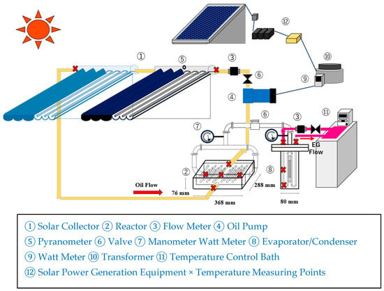
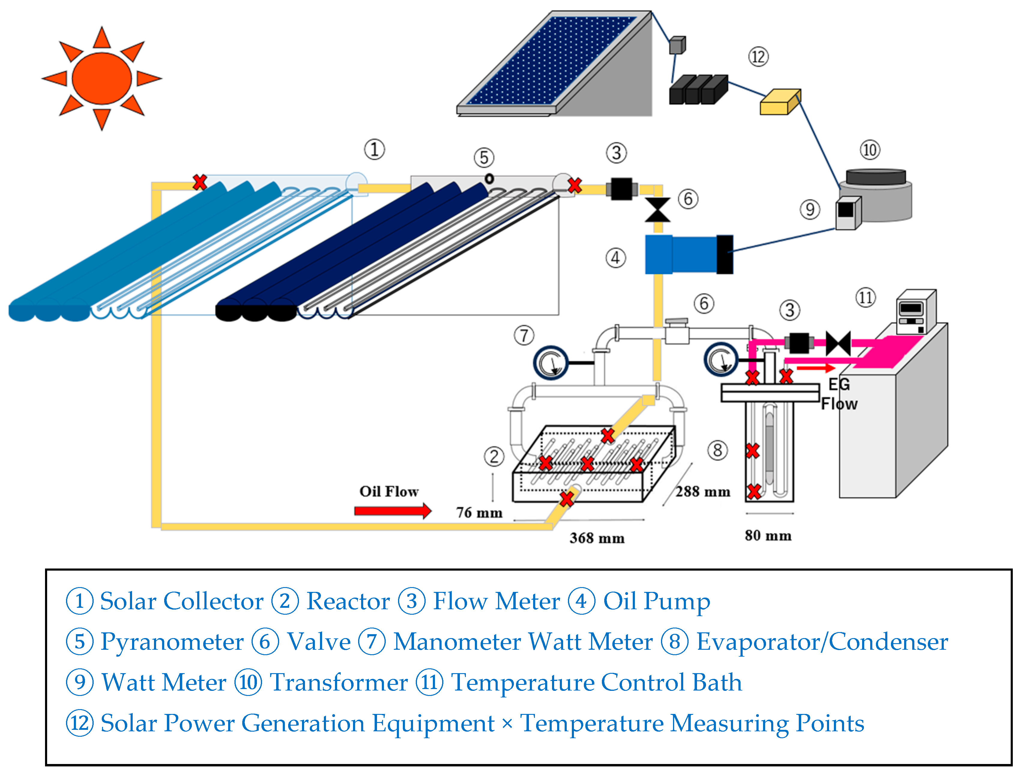
The schematic diagram of the SCHP experimental unit is shown in Figure 3. ① The solar collector (SC) is an evacuated-tube solar collector with CPC (compound parabolic concentrator) reflectors (SORARIS∞ CPC1506, 1 m2 per collector, Terada Iron Works Co., Ltd. Fukuyama, Japan). ② The reactor (Re) is constructed of stainless steel with a compact profile (200 mm × 368 mm × 76 mm). It has 23 heat-exchanging tubes with an outer diameter of 5.3 mm. Commercial Australian gypsum was sieved to obtain particles in the size range of 710–1000 μm. A total of 2400 g of CaSO4·1/2H2O was packed into the reactor. The particle size distribution and packing amount were selected based on the optimum conditions identified in previous studies [16]. ⑧ The evaporator/condenser is made of stainless steel in a prismatic shape (80 mm × 80 mm × 200 mm). ⑦ The reactor and condenser pressures were measured using a capacitance manometer (CCMT-100A, ULVAC, Chigasaki, Japan; accuracy: ±0.2%). ④ An Oil Magnet Pump (MMP, Sanwa Hydrotech Co., Ltd. Suita, Japan) is used as the heat exchange media (HEM) circulation pump. ⑤ Solar irradiance was measured using a pyranometer (ML-01, EKO Instruments Co., Ltd. Shibuyaku, Japan; accuracy: ±0.2%), which was installed at the same tilt angle as the solar collector. ⑨ The electrical power consumption of the HEM circulation pump was measured using a power meter (EC-03, Custom Co., Ltd. Chiyodaku, Japan; accuracy: ±10%). ③ The HEM flow rate was measured using a flow meter (RR940N, Tokyo Keiso Co., Ltd. Minatoku, Japan; accuracy: ±0.2%). ⑫ A photovoltaic system supplies the electrical power required by the oil circulation pump. Temperatures at the measurement points indicated in Figure 3 were recorded using T-type sheathed thermocouples (diameter: 1 mm; accuracy: ±0.6 K). To decrease heat loss, surfaces of the pipes, reactor, and evaporator/condenser are thoroughly insulated with glass wool.
Figure 3.
Schematic diagram of the standalone solar chemical heat pump (SCHP) experimental unit and measurement points.
2.2. Experimental Procedure
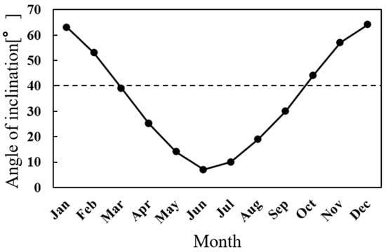
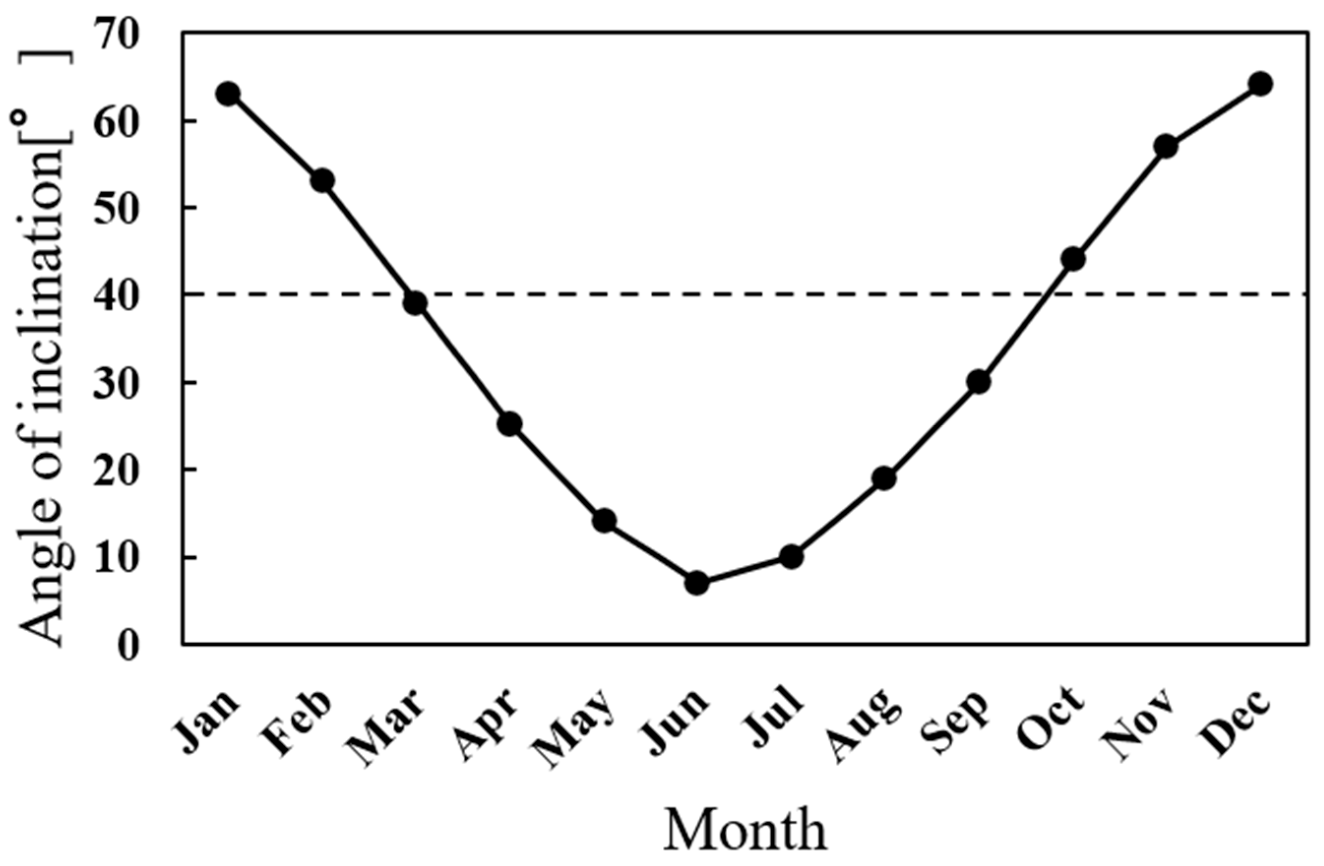
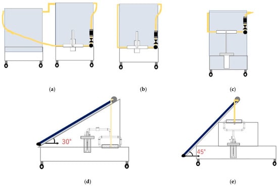
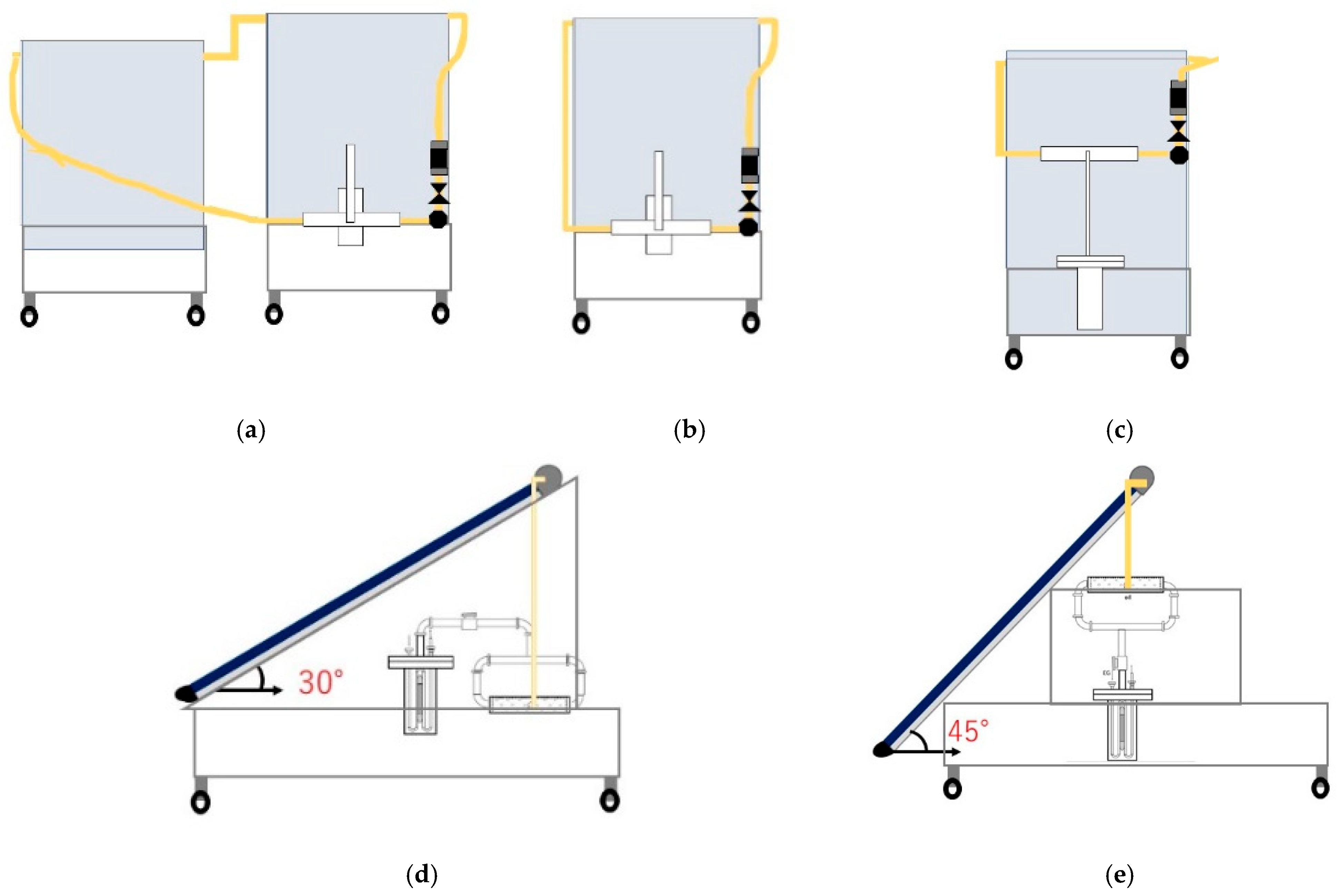
In this study, the layout of the SCHP apparatus is modified under autumn meteorological conditions in Japan. The experiments are carried out at the Nishi-Chiba Campus of Chiba University (Chiba, Japan; 140.1° E, 35.62° N) in autumn (September and October). The ambient temperature ranged from 296 to 299 K. Table 1 shows the conditions and methods of the three types of experimental setups. To reduce the footprint of the system, Type 2 uses one SC. Therefore, the length of the pipe is 0.59 times that of Type 1. Type 3 uses one SC, and the position of the CHP unit was optimized, reducing the piping length to 70% of that of Type 1. Figure 4 presents the best angle of inclination [22], and the collector tilt angle in Type 3 is set to the optimal angle in autumn. The SC is fixed due south. Figure 5 represents the schematics of each experimental apparatus.
Table 1.
Conditions and methods of the three types of experimental setups.
Figure 4.
Recommended solar collector tilt angle for Chiba, Japan (adapted from Ref. [22]).
Figure 5.
Photographs of the experimental configurations. (a) Type 1 (rear view); (b) Type 2 (rear view); (c) Type 3 (rear view); (d) Type 1 and Type 2 (side view); (e) Type 3 (side view).
The experiments were conducted under naturally varying outdoor conditions, which limited the possibility of repeated measurements under identical operating conditions. This limitation should be considered when interpreting the quantitative comparisons presented in this study.
In the sensible heat storage phase, to raise the temperature of CaSO4∙1/2H2O, HEM is circulated through the SC and reactor after the reactor is evacuated using a vacuum pump. The minimum temperature required for chemical heat storage is set at 368 K. Since the flow rate does not rise immediately at the beginning, the measurement is started after it reaches a predetermined value. This is why the maximum flow rate is 2 L/min in the sensible heat storage phase. Before the chemical heat storage experiment, the condenser is evacuated with a vacuum pump until it reaches the saturated vapor pressure of the ethylene glycol aqueous solution. After confirming that the temperature of the particle bed exceeds 368 K and that the pressure of the reactor is higher than that of the condenser, the connecting valve between the reactor and the condenser is opened. The sensible heat storage experiment and the chemical heat storage experiment are carried continuously. The internal pressure of the reactor, the internal pressure of the evaporator/condenser, the temperature of the particle bed, and the HEM temperatures at the SC and Re inlet/outlet are recorded by a data logger, and the solar irradiance is measured with a pyranometer.
2.3. Calculation Method
The heat quantity of the HEM is calculated using the following equation:
where TSC_out is the SC outlet temperature and TSC_in is the SC inlet temperature. The recovered heat in the SC is calculated by using Equation (1). Similarly, the heat exchanged with the reactor is determined according to Equation (2). The reaction rate of CaSO4∙1/2H2O is obtained from the change in the water level of the evaporator/condenser with the following equation:
where ∆mwater is the change in the amount of water during the chemical heat storage experiment, mCaSO4 is the mass of CaSO4, and M represents the respective molecular weights. The accuracy of X depends on the water level meter (accuracy ±1%).
QSC [W] = wc (TSC_out − TSC_in),
QRe [W] = wc (TRe_in − TRe_out),
X [%] = ∆mwater/mCaSO4/(1/2 × Mwater/MCaSO4),
The power required for the circulation of the HEM is calculated based on the friction energy loss.
- Major head loss (Darcy–Weisbach equation):
∆Pliner = f × L × ρ × U2/2D,
∆Pcurve = (ξ + λl/d) × ρ × U2/2,
ξ = {0.131 + 0.1632(d/r)3.5} × θ/90
3. Results and Discussion
3.1. Baseline System Performance and HEM Circulating Power
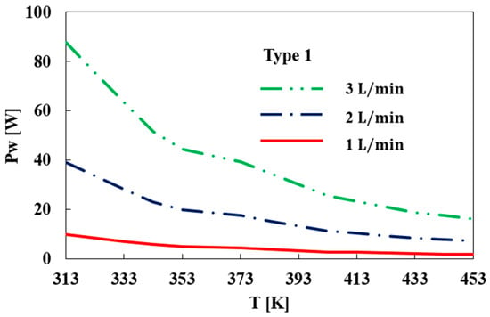
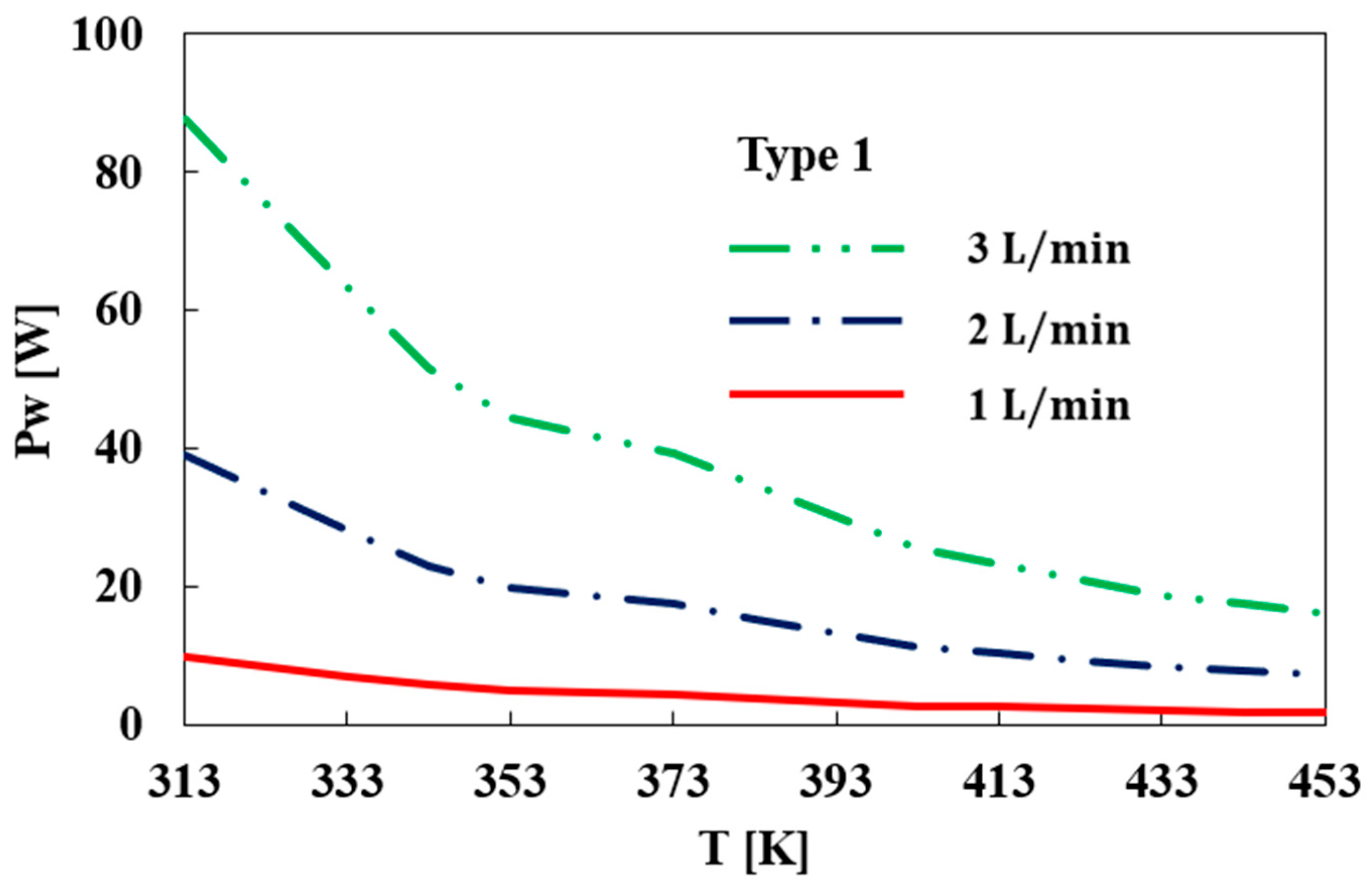
An external power supply is required to circulate the HEM. Therefore, the electrical power required to compensate for this demand using photovoltaic power generation is an important consideration. Figure 6 displays the circulation pump power consumption at each temperature in 1, 2, and 3 L/min of Type 1. Here, 2 L/min is three times as much circulation pump power consumption as 1 L/min and 3 L/min is twice as much circulation pump power consumption as 2 L/min at 313 K. Although the circulation power consumption increased with increasing HEM flow rate, the additional electrical demand remained relatively small compared with the amount of stored thermochemical energy, especially in the high-temperature heat storing range. Furthermore, the required pumping power can be supplied by a compact photovoltaic system. Therefore, the HEM flow rate can be increased to enhance reactor heat transfer without imposing a significant energy penalty on the standalone SCHP system.
Figure 6.
Effects of HEM flow rate on the circulation pump power consumption in Type 1.
These results indicate that pumping-power requirements are not a major constraint in the residential SCHP design and that flow-rate optimization should primarily focus on maximizing thermochemical storage performance.
3.2. Effect of Flow Rate of HEM on Sensible Heat Storage Experiment
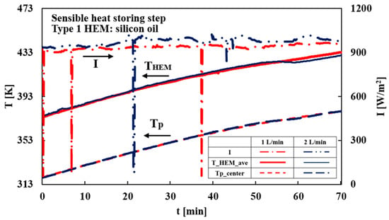
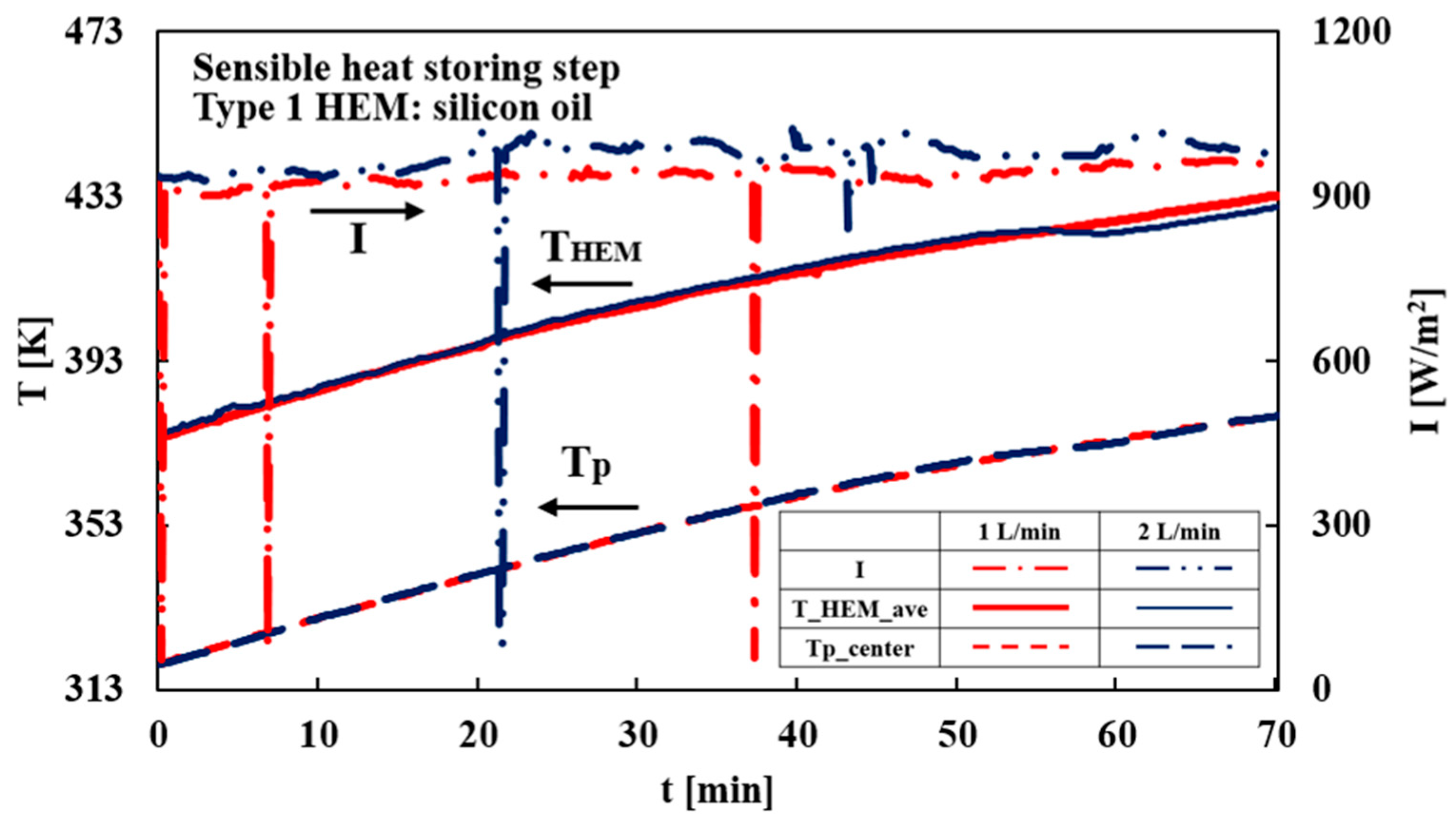
Figure 7 shows the temperature of the HEM on average and in the center of the particle bed, and solar radiation per unit area comparing 1 L/min to 2 L/min in Type 1. It should be noted that the maximum flow is 2 L/min because the viscosity of silicon oil is high at the first low-temperature range. The solar irradiance conditions were comparable between the 1 and 2 L/min experiments, and the heating rate of each HEM and the particle bed are almost same.
Figure 7.
Temporal variations in average HEM, particle bed center temperature and solar irradiance in Type 1 at an HEM flow rate of 1 and 2 L/min.
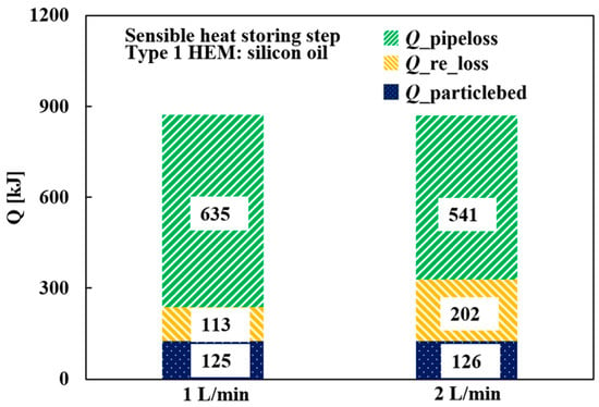
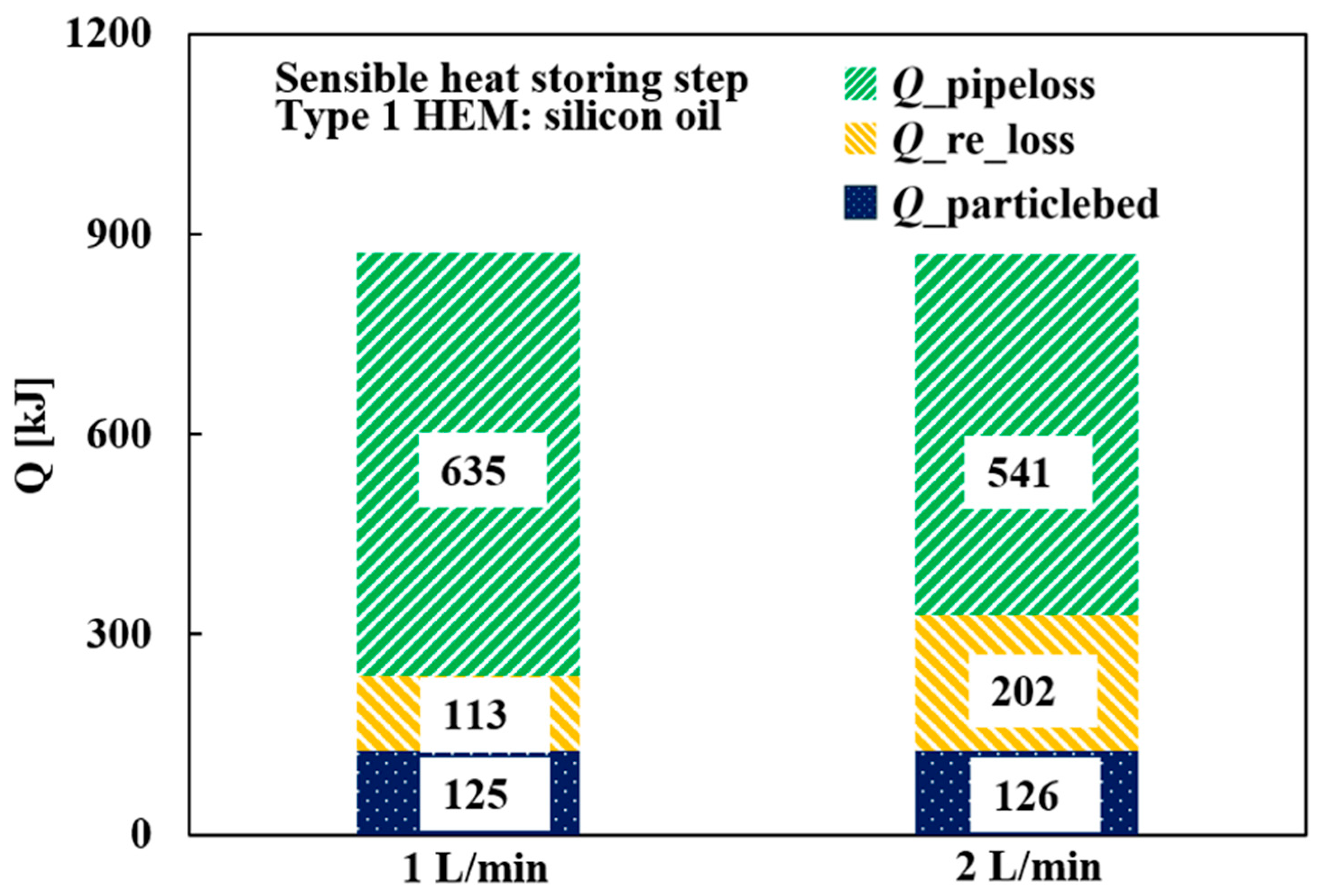
Figure 8 represents the stored sensible heat in the particle bed reactor and heat loss before the temperature of the particle bed reaches 380 K comparing 1 L/min to 2 L/min in Type 1. The ratio of heat loss in the pipe to the recovered heat in the SC decreases by 15% in 2 L/min. However, the ratio of heat loss in the reactor increases by 78% in 2 L/min. As a result, the amount of sensible heat stored in the reactor was nearly identical in both cases. Although increasing the HEM flow rate reduced heat loss in the piping section, the sensible heat stored in the particle bed showed little variation. This finding suggests that heat transfer within the particle bed rather than heat transport through the HEM circuit governs sensible heat storage performance.
Figure 8.
Comparison of sensible heat stored in the reactor particle bed and thermal losses during the sensible heat storage process in Type 1 at flow rates of 1 and 2 L/min.
Because the thermal resistance between the heat exchanger surface and the packed particle bed remained dominant, the benefit of increasing the HEM flow rate was limited during the sensible heat storage phase. Therefore, further enhancement of sensible heat storage requires improvements in reactor-side heat transfer rather than additional increases in flow rate.
3.3. Optimization of HEM Flow Rate on Chemical Heat Storage Experiment
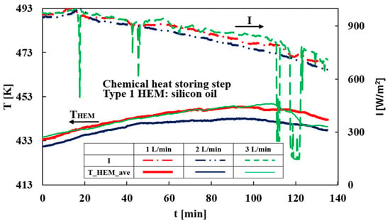
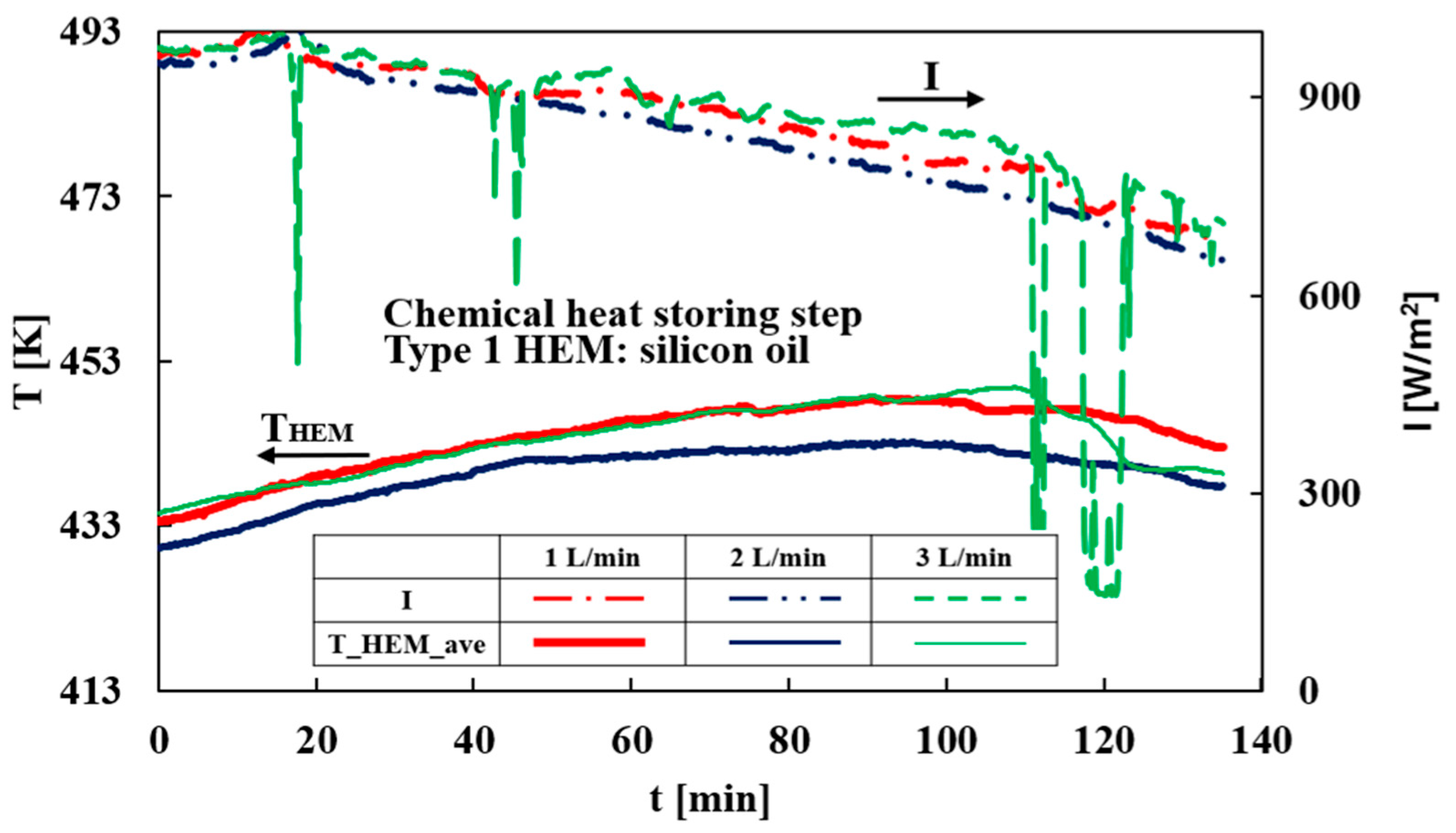
The experiments for the chemical heat storing step are conducted under various flow rates of 1, 2, and 3 L/min. Figure 9 shows the temperature of the HEM on average and solar radiation per unit area in 1, 2, and 3 L/min. In case of 1 and 3 L/min, the temperature of HEM is maintained at around 440 K, which is higher than case of 2 L/min. This is because the temperature at the start of the chemical heat storage step is high in 1 and 3 L/min.
Figure 9.
Temporal variations in average HEM temperature and solar irradiance during the thermochemical heat storage process in Type 1 at HEM flow rates of 1, 2, and 3 L/min.
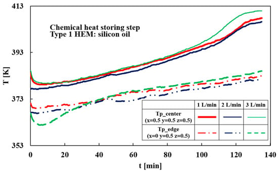
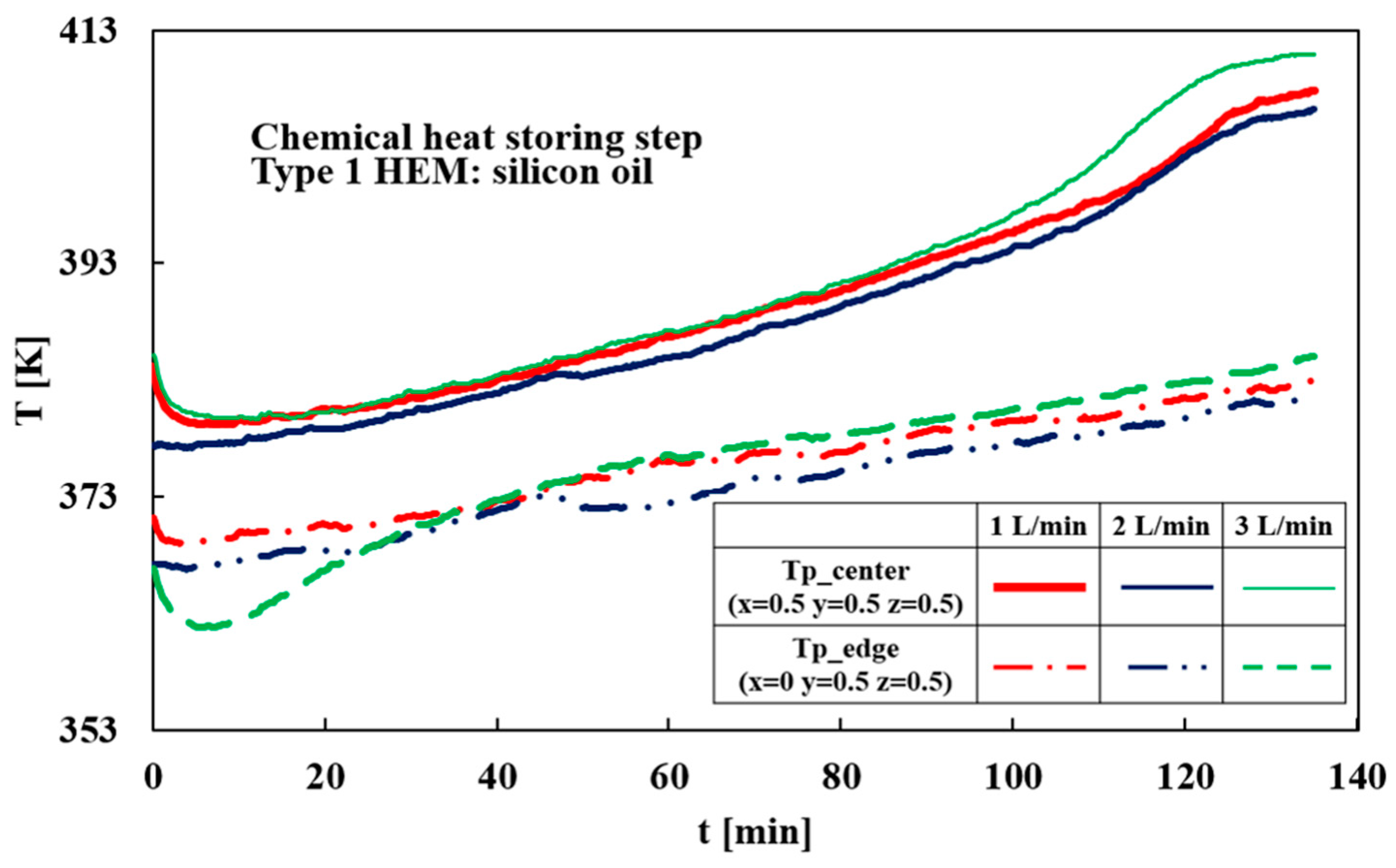
Figure 10 presents the temperature of the center and the edge of the particle bed in 1, 2, and 3 L/min. The temperature at the center in case of 1 and 3 L/min similarly decreases. However, the temperature at the edge in case of 3 L/min decreases the most. The heating rate at center varies after 100 min because CaSO4 completes chemical heat storing and restarts sensible heat storing.
Figure 10.
Temporal variations in particle bed temperature at the center and edge during the thermochemical heat storage process in Type 1 at HEM flow rates of 1, 2, and 3 L/min.
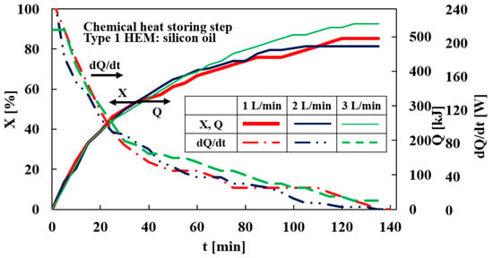
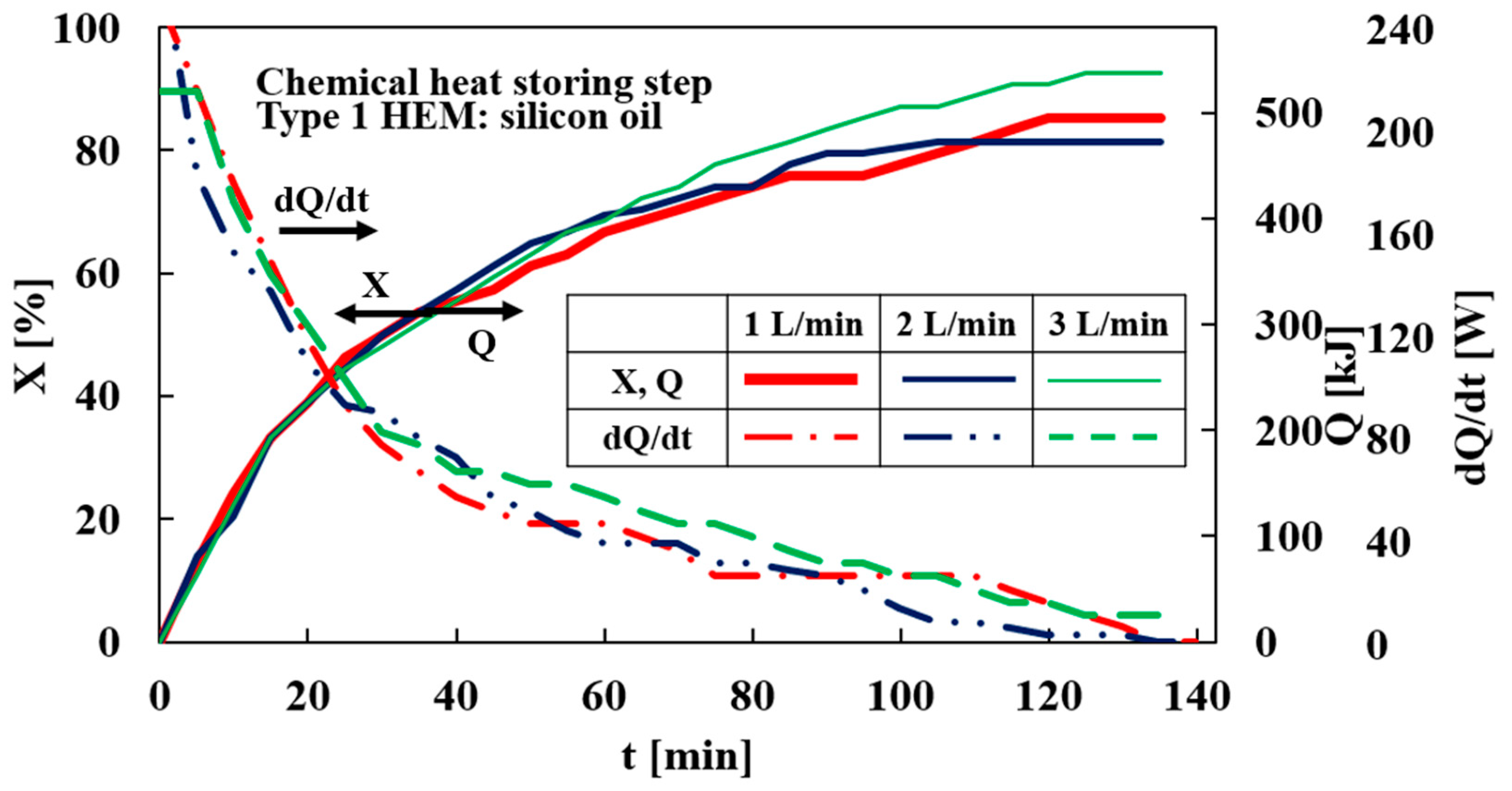
Figure 11 represents conversion rates and the chemically stored heat at 1, 2, and 3 L/min. Each conversion rate in case of 1 and 3 L/min is better than that at 2 L/min at first. This can be attributed to the high HEM temperatures. However, the conversion rates at 1 and 2 L/min are about 80% in the end. In 3 L/min, the conversion rate reaches 93%, and the chemical stored heat reaches 537 kJ. This can be attributed to the fact that the temperature drop at the edge of the particle bed at 3 L/min is the largest of the three cases. Therefore, the temperature difference between the particle bed and the HEM increases, which promotes heat exchange. The reaction rates at 1 and 2 L/min were nearly identical even though the temperature of the HEM at 2 L/min is lower than that at 1 L/min. This is also because the temperature drop is larger than that at 1 L/min, which enhanced the heat transfer rate.
Figure 11.
Conversion rate changes in the dehydration reaction and chemical heat storage capacity in Type 1 at HEM flow rates of 1, 2 and 3 L/min.
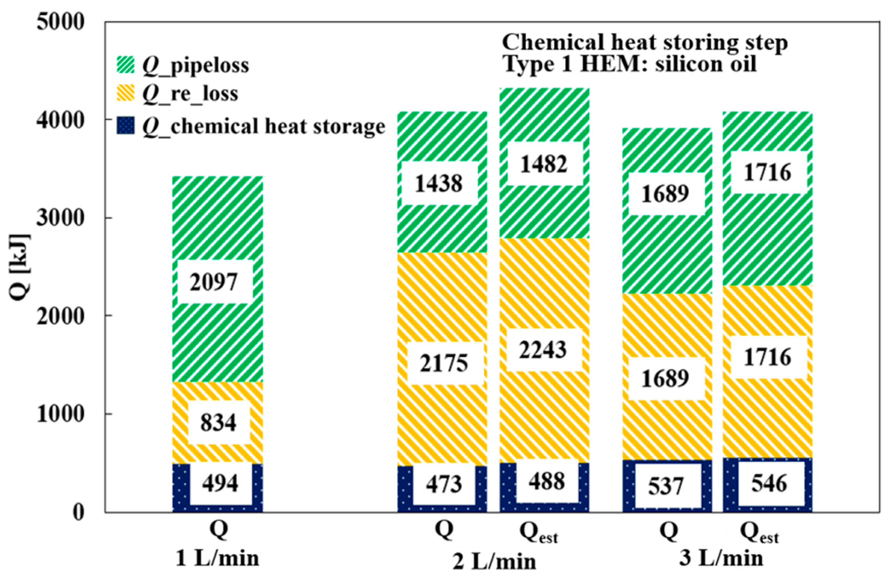
Figure 12 displays chemically stored heat and heat loss. The estimated values Qest under equivalent irradiation conditions for the case of 1 L/min are also presented. Because perfectly identical solar irradiation conditions could not be obtained for all experiments under natural outdoor weather conditions, these estimated values were included to facilitate a more meaningful comparison. Heat exchanged with reactor at 2 and 3 L/min is larger than that at 1 L/min. This is because the temperature difference between particle bed and HEM at 2 and 3 L/min is larger than that at 1 L/min. On the other hand, the heat loss in 3 L/min is bigger than that in 2 L/min. Since the HEM temperature at 3 L/min is higher, the temperature difference between the fluid and the ambient air at 3 L/min is larger than that at 2 L/min. It is found that the heat transfer rate between HEM and the reactor is increased at 2 and 3 L/min. Therefore, 2 and 3 L/min enhance the reaction rate by proceeding into the edges of the particle bed.
Figure 12.
Comparison of chemical heat storage capacity and thermal losses in Type 1 at HEM flow rates of 1, 2 and 3 L/min.
The results clearly demonstrate that HEM flow rate has a greater influence on thermochemical storage performance than on sensible heat storage performance. While the reactor temperature behavior was similar among the three cases, the final conversion strongly depended on flow rate. At 3 L/min, the conversion reached approximately 93% and the chemical heat storage capacity reached 537 kJ, representing the highest values obtained in this study. The improved performance can be attributed to enhanced heat transfer between the heat exchanger tubes and the peripheral region of the particle bed, which allowed a larger fraction of the packed CaSO4 to participate in the dehydration reaction.
These findings suggest that reactor-side heat transfer is a key limiting factor during thermochemical heat storage. Consequently, optimizing HEM flow rate is an effective strategy for improving reaction utilization and maximizing stored chemical energy. Accordingly, a flow rate of 3 L/min was selected for the subsequent system-miniaturization study.
3.4. Layout Optimization for a Compact SCHP
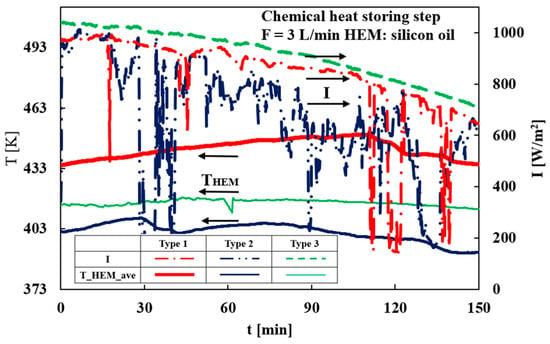
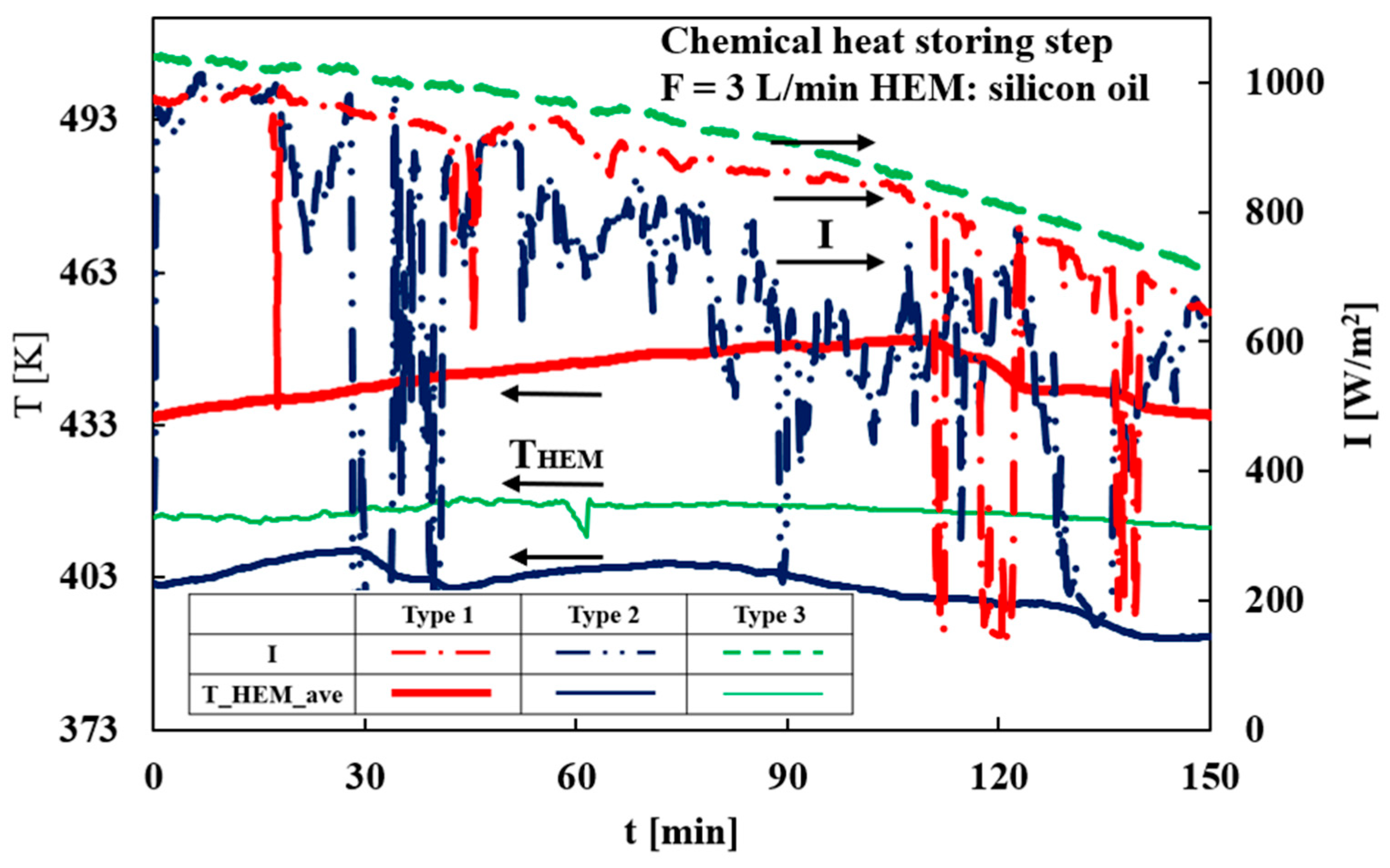
In this subsection, the performance of Type 2 and 3 is compared with Type 1 in case of 3 L/min. Figure 13 shows the temperature changes in the HEM on average and solar radiation per unit area in Type 1, 2, and 3 at 3 L/min. In Type 3, the solar radiation per unit area is the greatest and the temperature of HEM is maintained at around 415 K. On the other hand, the temperature of HEM in Type 2 is around 403 K. This is because the angle of the SC in Type 3 is the best in autumn and the solar radiation in Type 2 is not stable.
Figure 13.
Temporal variations in average HEM temperature and solar irradiance in the Type 1, Type 2 and Type 3 configurations at an HEM flow rate of 3 L/min.
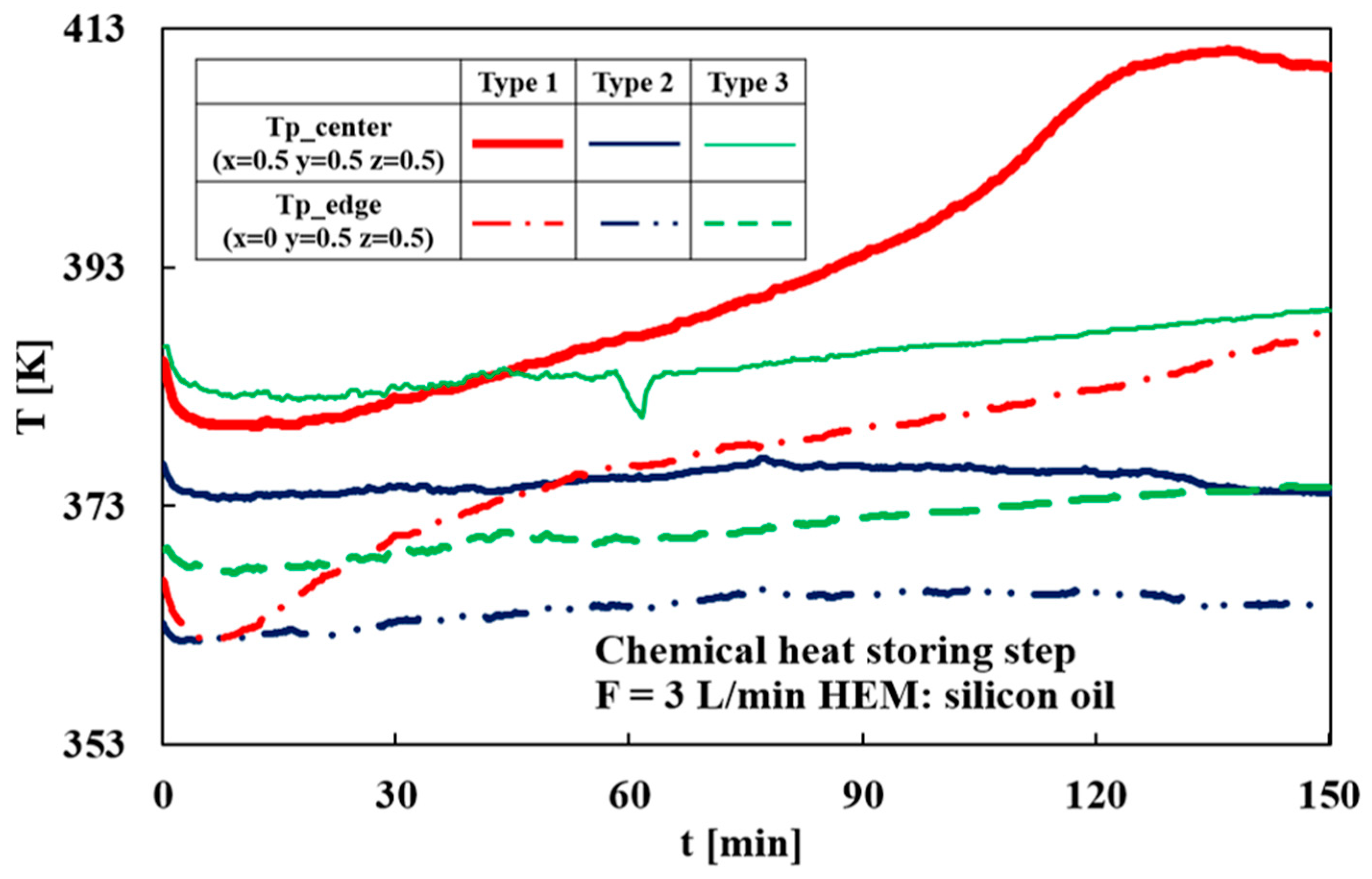
Figure 14 presents the temperature changes at center and edge of the particle bed in Type 1, 2, and 3 at 3 L/min. In both Type 2 and 3, the initial temperature is 383 K. However, the temperature drop during the dehydration reaction is not as large as that in Type 1. This behavior is attributed to the approximately 20 K higher HEM temperature due to the two SCs observed in Type 1.
Figure 14.
Temporal variations in particle bed temperature at the center and edge during the thermochemical heat storage process in Type 1, 2 and 3 at an HEM flow rate of 3 L/min.
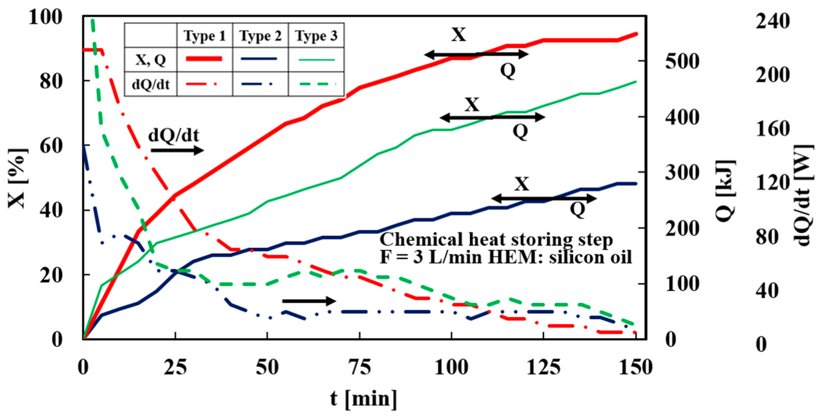
Figure 15 represents the conversion rates and chemically stored heat in Type 1, 2, and 3. The reaction rate of Type 1 is higher than those of Types 2 and 3 and reaches 94% in 150 min. The chemical stored heat reaches 548 kJ. Furthermore, while Type 1 exhibits a higher heat storage rate before 90 min, Types 2 and 3 surpass it after 90 min. This is because the reaction velocity in Types 2 and 3 becomes more gradual. Type 3 has a higher heat storage rate than Type 2. This can be attributed to the vertical CHP connection and the higher HEM temperature due to a smaller pipe length and high solar radiation.
Figure 15.
Conversion rate changes in the dehydration reaction and chemical heat storage capacity among the Type 1, 2 and 3 configurations at an HEM flow rate of 3 L/min.
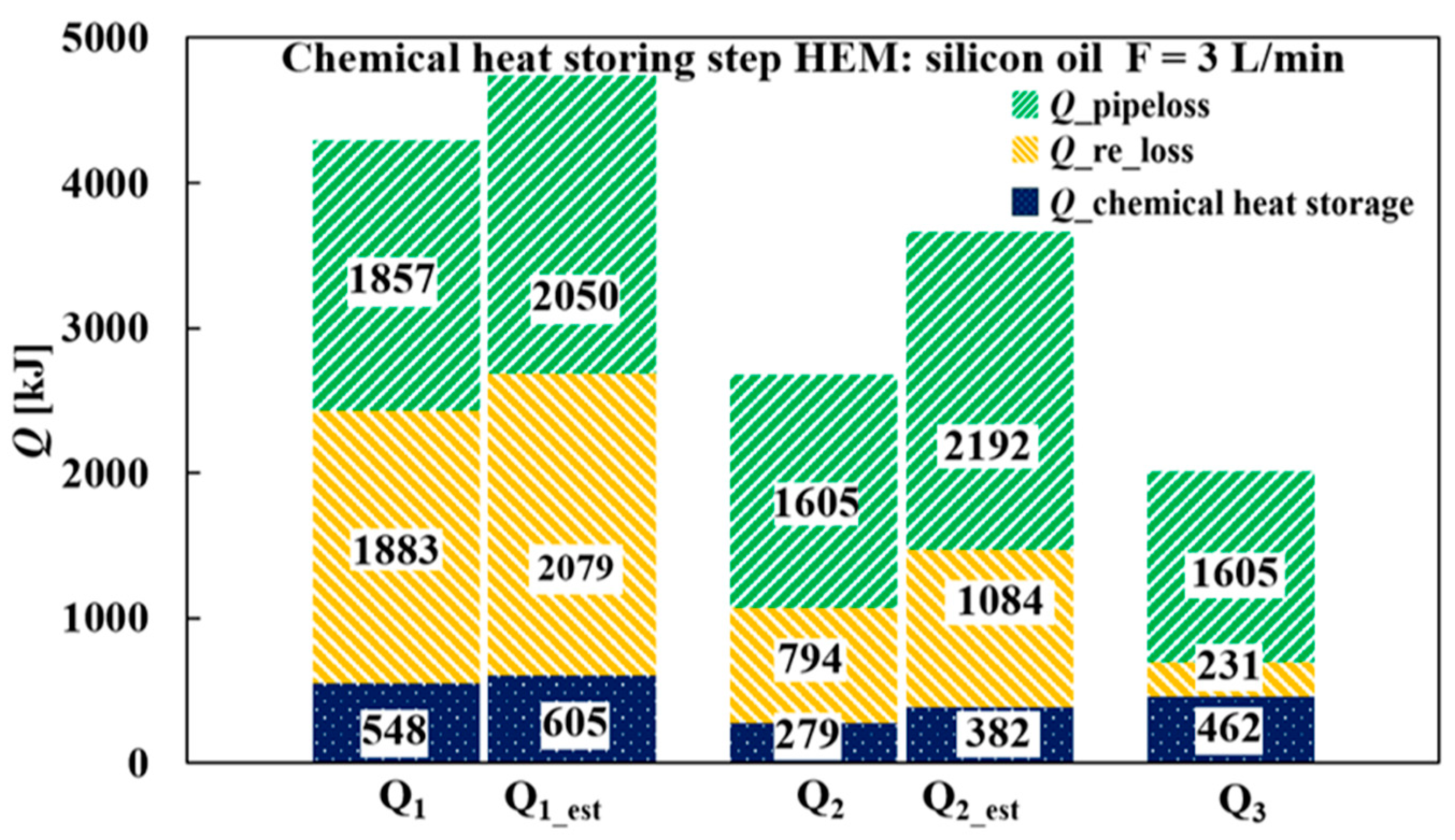
Figure 16 displays the chemically stored heat and heat loss in Type 1, 2, and 3. The estimated values Qest under equivalent irradiation conditions for Type 3 are also presented. A key outcome of this study is that the reduction in collector area did not result in a proportional reduction in thermochemical storage performance. Type 3 employed only one solar collector, corresponding to a 50% reduction in collector area compared with the baseline Type 1 configuration. Nevertheless, the chemical heat storage capacity remained as high as 462 kJ, corresponding to 84% (76% for estimated values under equivalent solar irradiation conditions) of the 548 kJ obtained in Type 1. In other words, a 50% reduction in collector area resulted in only a 16% (24% for estimated same amount Ir) decrease in chemical heat storage capacity.
Figure 16.
Comparison of chemical heat storage capacity and thermal losses among the Type 1, Type 2, and Type 3 configurations.
This result demonstrates that the performance penalty associated with collector downsizing can be substantially mitigated through system-level optimization. The improved performance of Type 3 can be attributed to two major factors. First, the collector tilt angle was optimized for autumn operation, increasing the effective utilization of available solar irradiation. Second, the shortened piping network reduced thermal losses during heat transport from the solar collector to the reactor. Furthermore, the comparison between Types 2 and 3 highlights the importance of apparatus layout. Although both systems employed the same collector area, Type 3 achieved significantly higher heat storage performance owing to reduced thermal losses and improved heat utilization.
These findings indicate that collector area alone should not be regarded as the dominant design parameter for residential SCHPs. Instead, thermal-loss management and system integration play equally important roles in determining overall system performance. Therefore, layout optimization represents an effective strategy for improving the performance-to-size ratio of compact SCHP systems.
4. Conclusions
A standalone CaSO4 solar chemical heat pump (SCHP) driven by solar thermal energy and a photovoltaic-powered heat exchange medium (HEM) circulation system was experimentally investigated. The effects of HEM flow rate, collector configuration, and apparatus layout on thermochemical heat storage performance were evaluated with the aim of establishing design guidelines for compact residential SCHPs under moderate solar irradiation conditions in autumn.
The main findings are summarized as follows:
Increasing the HEM flow rate enhanced heat transfer within the reactor and promoted the dehydration reaction of CaSO4. The highest performance was obtained at an HEM flow rate of 3 L/min, achieving a conversion of approximately 93% and a chemical heat storage capacity of 537 kJ in the baseline Type 1 configuration equipped with two solar collectors (2 m2).
Optimization of the collector tilt angle and reduction in piping length improved solar energy utilization and reduced thermal losses during heat transport from the solar collector to the reactor.
Although the collector area was reduced by 50%, the optimized Type 3 (1 m2) configuration achieved a chemical heat storage capacity of 462 kJ, corresponding to approximately 84% of that obtained in the baseline Type 1 (2 m2) system. In other words, a 50% reduction in collector area resulted in only a 16% reduction in thermochemical heat storage capacity.
These experimental results demonstrate that collector area is not the sole determinant of SCHP performance. Appropriate system-level optimization, including flow-rate control, collector-angle adjustment, and piping-layout design, can substantially mitigate performance losses associated with collector downsizing. The proposed design provides a practical pathway toward compact residential SCHPs with reduced installation space requirements while maintaining high thermochemical heat storage performance. Future work will focus on enhancing heat and mass transfer within the reactor to further improve both the compactness and thermochemical performance of the SCHP system.
Author Contributions
Conceptualization, H.O.; methodology, H.O.; investigation, H.O. and Y.H.; formal analysis, H.O. and Y.H.; validation, H.O. and Y.H.; visualization, H.O. and Y.H.; writing—original draft preparation, H.O. and Y.H.; writing—review and editing, H.O.; supervision, H.O.; project administration, H.O. All authors have read and agreed to the published version of the manuscript.
Funding
This research received no external funding.
Data Availability Statement
Data will be made available on request.
Conflicts of Interest
The authors declare no conflicts of interest.
Abbreviations
| Nomenclature | ||
| c | Specific heat capacity | (kJ/kg/K) |
| D | Diameter | (m) |
| f | Darcy friction factor | (-) |
| L | Length | (m) |
| M | Molecular weight | (kg/mol) |
| m | Mass | (kg) |
| P | Pressure | (Pa) |
| Pw | Circulation power | (W) |
| Q | Thermal energy | (kJ) |
| T | Temperature | (K) |
| t | Time | (min) |
| U | Flow velocity | (m/s) |
| w | Mass flow rate | (kg/s) |
| X | Conversion | (%) |
| ε | Loss coefficient | (-) |
| λ | Pipe friction factor | (-) |
| ρ | Density | (kg/m3) |
| Subscript | ||
| ave | Average | |
| Co | Condenser | |
| d | Dehydration | |
| Ev | Evaporator | |
| e | Equilibrium | |
| H | High | |
| h | Hydration | |
| HEM | Heat exchange medium | |
| in | Inlet | |
| k | Reaction rate constant | |
| out | Outlet | |
| P | Particle | |
| R | Releasing | |
| Re | Reactor | |
| r | Radius | |
| S | Storing | |
| SC | Solar collector | |
| s | Saturated | |
| η | Diameter influence term | |
References
- Wongsuwan, W.; Kumar, S.; Neveu, P.; Meunier, F. A review of chemical heat pump technology and applications. Appl. Therm. Eng. 2001, 21, 1489–1519. [Google Scholar] [CrossRef] [Scilit]
- Krishnadoss, R.; Dyrland, I.A.; Thomas, A.A. Design and optimization of alcohol-ketone-hydrogen chemical heat pumps. Comput. Chem. Eng. 2025, 199, 109158. [Google Scholar] [CrossRef] [Scilit]
- National Laboratory of the Rockies. Champion Photovoltaic Module Efficiency Chart. Available online: https://www.nlr.gov/pv/module-efficiency (accessed on 28 September 2026).
- Kaushik, S.C.; Verma, A.; Tyagi, S.K. Advances in solar absorption cooling systems: An overview. J. Therm. Eng. 2024, 10, 14744. [Google Scholar] [CrossRef] [Scilit]
- Prajapati, S.; Patel, D.K.; Bhargav, H.; Chan, C.K.; Singh, S.; Varshney, D. Performance enhancement of activated carbon-methanol solar adsorption system using coaxial collector and dual-valve stability. Int. J. Thermofluids 2026, 33, 101608. [Google Scholar] [CrossRef] [Scilit]
- Fadhel, M.I.; Sopian, K.; Daud, W.R.W.; Alghoul, M.A. Review on advanced of solar assisted chemical heat pump dryer for agriculture produce. Renew. Sustain. Energy Rev. 2011, 15, 1152–1168. [Google Scholar] [CrossRef] [Scilit]
- Ibrahim, M.; Sopian, K.; Daud, W.R.W.; Alghoul, M.A.; Yahya, M.; Sulaiman, M.Y.; Zaharim, A. Solar Chemical Heat Pump Drying System for Tropical Region. WSEAS Trans. Environ. Dev. 2009, 5, 404–413. [Google Scholar]
- Wang, R.; Hong, H.; Sun, J.; Jin, H. A solar hybrid system integrating concentrating photovoltaic direct steam generation by chemical heat pump. Energy Convers. Manag. 2019, 196, 856–865. [Google Scholar] [CrossRef] [Scilit]
- Zhang, Y.; Gao, Z.; Yu, J.; Jia, T.; Zhou, D.; Zhao, Y.; Dai, Y. Efficient heat upgrading in concentrated solar thermal conversion using chemical heat pump. Energy 2026, 342, 139620. [Google Scholar] [CrossRef] [Scilit]
- Tamm, S.; Berberich, M. Solar Collector Technologies for District Heating: An Analysis of Technical and Economic Characteristics and System Integration. In IEA SHC Task 68 Report RA1; IEA: Paris, France, 2024. [Google Scholar] [CrossRef] [Scilit]
- Palacious, A.; Navarro, M.E.; Barreneche, C.; Diang, Y. Water sorption-based thermochemical storage materials: A review from material candidates to manufacturing routes. Front. Therm. Eng. 2022, 2, 1003863. [Google Scholar] [CrossRef] [Scilit]
- Kobayashi, E.; Hirose, Y.; Ogura, H. Improvement of Evaporator Performance in Chemical Refrigerator—Effects of Aqueous Solution Components and Mass Transfer. Trans. Jpn. Soc. Refrig. Air Cond. Eng. 2020, 37, 233–240. [Google Scholar] [CrossRef]
- Harrak, E.A.; Lahrar, E.H.; Slimani, H.; El karch, A.; Rmail, S.; Ait Ousaleh, H.; Faik, A. Thermodynamic and kinetics investigation of Phosphogypsum hydration/dehydration reaction for thermochemical energy storage. Appl. Therm. Eng. 2025, 279, 128079. [Google Scholar] [CrossRef] [Scilit]
- Karch, E.A.; Rmail, S.; Slimani, H.; El Harrak, A.; Sair, S.; Faik, A.; Ait Ousaleh, H. Doping gypsum with divalent metals for thermochemical energy storage: Enhancing stability and reversibility. J. Energy Storage 2026, 144, 119816. [Google Scholar] [CrossRef] [Scilit]
- Ogura, H.; Haguro, M.; Shibata, Y.; Otsubo, Y. Reaction Characteristics of CaSO4/CaSO4·1/2H2O Reversible Reaction for Chemical Heat Pump. J. Chem. Eng. Jpn. 2007, 40, 1252–1256. [Google Scholar] [CrossRef] [Scilit]
- Ogura, H.; Kubota, M.; Suzuki, H.; Yamakawa, T. Enhancement of Refrigeration Cold-Heat Production by Thermal Driven Chemical Heat Pump. Trans. Jpn. Soc. Refrig. Air Cond. Eng. 2015, 32, 373–380. [Google Scholar] [CrossRef] [Scilit]
- Ren, Y.; Ogura, H. Performance Evaluation of Off-grid Solar Chemical Heat Pump for Cooling/Heating. Sol. Energy 2021, 224, 1247–1259. [Google Scholar] [CrossRef] [Scilit]
- Ren, Y.; Ogura, H. Dynamic Simulations on Enhanced Heat Recovery Using Heat Exchange PCM Fluid for Solar Collector. Energies 2023, 16, 3075. [Google Scholar] [CrossRef] [Scilit]
- Wang, S.; Hoes, P.-J.; Hensen, J.L.M.; Adan, O.C.G.; Donkers, P.A.J. A design optimization method for solar-driven thermochemical storage systems based on building performance simulation. J. Energy Storage 2023, 72, 108354. [Google Scholar] [CrossRef] [Scilit]
- Su, Y.; Yang, Y.; He, G.; Liu, R.; Ding, D. Two-Stage Solar–NaOH Thermochemical Heat Pump Heating System for Building Heating: Operations Strategies and Theoretical Performance. Energies 2024, 17, 1976. [Google Scholar] [CrossRef] [Scilit]
- Ren, Y.; Ogura, H. Feasibility study with EnergyPlus simulation for solar chemical heat pump unit introduced into building as next-generation energy supply system. Energy Build. 2024, 313, 114256. [Google Scholar] [CrossRef] [Scilit]
- NEDO Solar Radiation Database. Available online: https://www.nedo.go.jp/seika_hyoka/ZZFF_100041.html (accessed on 10 September 2026).



Disclaimer/Publisher’s Note: The statements, opinions and data contained in all publications are solely those of the individual author(s) and contributor(s) and not of MDPI and/or the editor(s). MDPI and/or the editor(s) disclaim responsibility for any injury to people or property resulting from any ideas, methods, instructions or products referred to in the content. |
© 2026 by the authors. Licensee MDPI, Basel, Switzerland. This article is an open access article distributed under the terms and conditions of the Creative Commons Attribution (CC BY) license.