


Abstract
An advanced frequency study in thick-walled functionally graded material (FGM) spherical shells is investigated with advanced shear correction. The values of advanced shear correction can be greater than one, be a negative value, and be affected by a nonlinear term of third-order shear deformation theory (TSDT) of displacements, FGM power law index, and temperature. It is novel and interesting to consider using TSDT and advanced shear correction to derive a simple homogeneous equation with reasonable simplifications into a symmetrical sparse matrix subjected to free vibration. The zero determinant of the symmetrical sparse matrix can be expressed to calculate the natural frequency by Newton’s method. The parameter effects of advanced shear correction, a nonlinear TSDT term, temperature, and the FGM power-law index on the natural frequencies of thick-walled FGM spherical shells are presented. The natural-frequency data for the axial and circumferential mode shapes are obtained. This is a new finding, as the assumed simplification in a sparse matrix causes a numerical truncation error; the natural-frequency values of the presented sparse matrix are much greater than those in a full matrix for thick-walled FGM spherical shells.
1. Introduction
Free vibration studies in the materials of spherical shells were investigated for the natural frequency. In 2021, Bagheri et al. [1] presented the free vibration of a functionally graded material (FGM) conical-spherical shell by using the first-order shear deformation theory (FSDT) of displacements and considering various types of boundary conditions on the result of natural frequencies. In 2021, Liu et al. [2] used the three-dimensional (3D) elasticity theory and the state space method to study the free vibrations of functionally graded graphene platelets reinforced composite (FG-GPLRC) spherical shells. In 2021, Tang and Dai [3] used the multiscale method and hygrothermal effects to obtain the analytical results for the nonlinear free vibration of carbon fiber-reinforced polymer (CFRP) spherical shell panels. In 2021, Roy et al. [4] presented the modified higher order zigzag theory (HOZT) of displacements and the experimental modal by Bruel and Kjaer to study the free vibration of laminated composite hybrid and glass fiber reinforced plastic (GFRP) shells. In 2019, Sayyad and Ghugal [5] presented the results of free vibration for laminated spherical shells by using a generalized higher-order shell theory. In 2019, Li et al. [6] presented the free vibration analysis of combined spherical-cylindrical-spherical (CSCS) shells based on the Ritz method with thin FSDT of displacements. In 2019, Li et al. [7] presented the Ritz method and the FSDT of displacements to obtain the free vibration analyses for functionally graded porous spherical shell (FGPSS). In 2016, Fantuzzi et al. [8] presented two-dimensional (2D) computational models and 3D exact shell models for the free vibration of FGM shells. In 2010, Sepiani et al. [9] presented the numerical results of free vibration for FGM shells by using the FSDT of displacements without considering the thermal effect.
Mathematical simulation reviews on thick FGM spherical shell structures are presented. In 2020, Zannon et al. [10] presented a free vibration numerical study for thick-walled FGM spherical shells by using the third-order shear deformation theory (TSDT) model. In 2023, Keibolahi et al. [11] presented a thermal-shock vibration numerical study for deep FGM spherical shells by using the FSDT model. In 2017, Khoa and Tung [12] presented a pressure load study for moderately-thick FGM sandwich spherical shells by using the FSDT model. In 2025, Zhang et al. [13] presented a thermal and mechanical loads static study for thick FGM spherical shells by using a heat conduction model. In 2026, Nejad et al. [14] presented a pressure load study for an FGM spherical solid by using the plane-elasticity theory (PET) model. In 2021, Dastjerdi et al. [15] presented a mathematical study for thick FGM spherical shells by using the FSDT model. In 2022, Arslan and Mack [16] presented a pressure load stress study for thick FGM spherical shells by using the homogenized-properties model. In 2014, Khaire et al. [17] presented a free vibration numerical study for FGM spherical shells by using the higher-order shear deformation theory (HSDT) model. In 2020, Zeverdejani and Kiani [18] presented a thermal-shock vibration numerical study for FGM spherical shells. In 2019, Shariyat and Ghafourinam [19] presented a pressure load stress study for thick FGM spherical shells by using Norton’s creep model.
Free vibration computational studies with shear correction effect in FGM spherical shells under environment-temperature were investigated for natural frequency. In 2020, Hong [20] used TSDT to present the frequency results for thick-walled FGM spherical shells with a simple homogeneous equation and varied shear correction, which was usually positive, smaller than one, and not affected by the nonlinear TSDT term. It is novel and interesting to investigate the natural frequency for thick-walled FGM spherical shells with advanced shear correction, whose value can be greater than one, can be a negative value, and can be affected by the nonlinear TSDT term. Four parameter effects of advanced shear correction, nonlinear TSDT term, temperature, and FGM power law index on the natural frequencies of thick-walled FGM spherical shells for a given angle with respect to the z axis and radius are investigated.
It is interesting to investigate what is fundamentally new on the effects of natural frequency, e.g., treatment of advanced shear correction presented in Section 2.2, Section 2.3, Section 3 and Section 4; nonlinear TSDT term effects presented in Section 2.1, Section 3 and Section 4; temperature dependency on FGMs presented in Section 3 and Section 4; and compared homogeneous equation in sparse matrix and full matrix presented in Section 2.4 and Section 4.
2. Materials and Methods
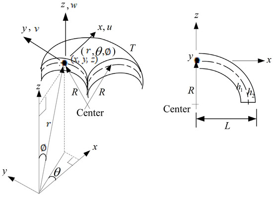
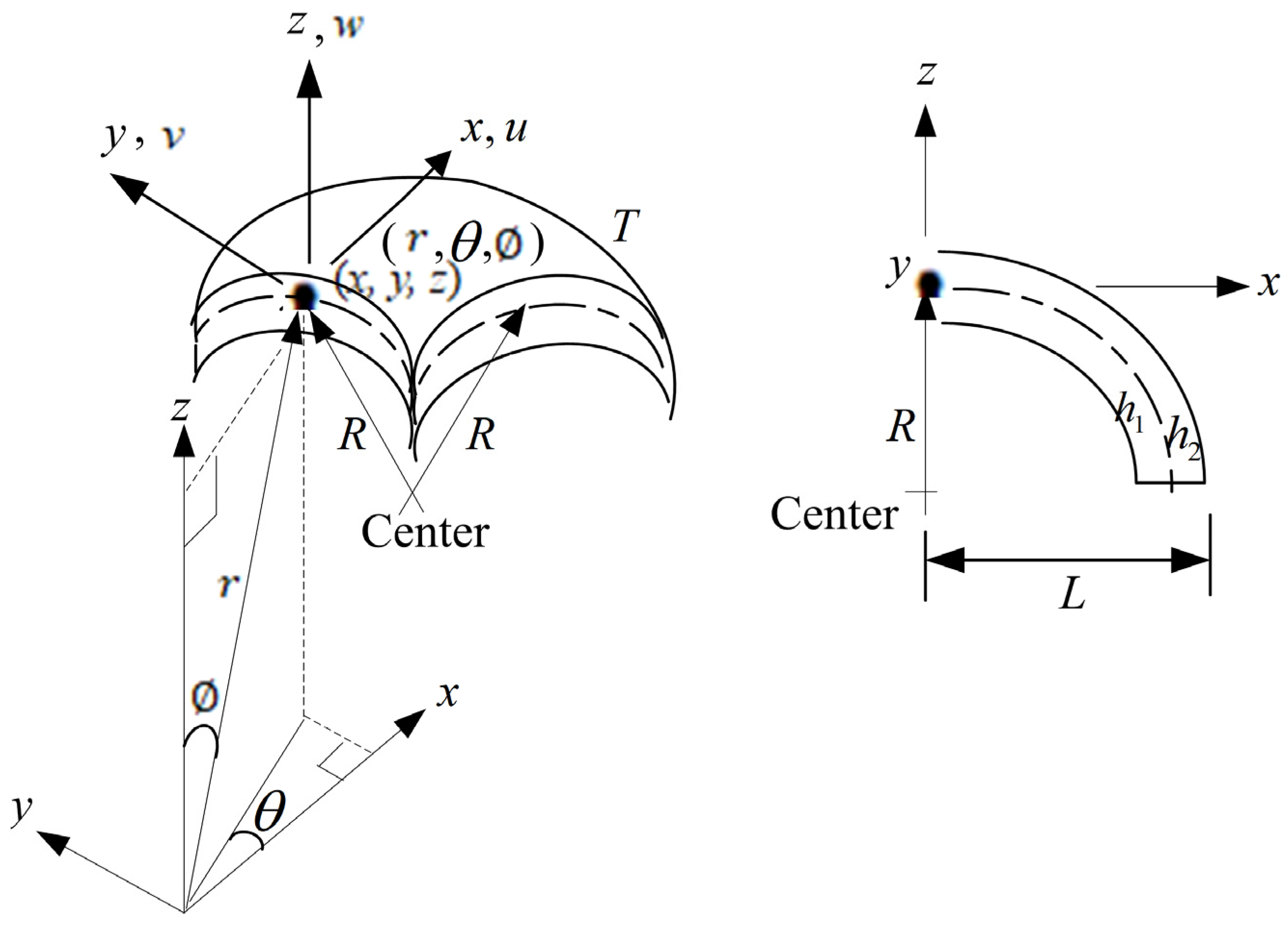
A two constituent-material in thick-walled FGM spherical shells has FGM material 1 on the inner layer and FGM material 2 on the outer layer [20]. A position point on FGM spherical shells in two coordinate systems between spherical axes and Cartesian axes (x, y, z) is displayed in Figure 1, where r denotes the radius, is the circumferential angle, and is the angle between the z axis and the r axis. The power law function type material properties of FGM spherical shells are considered. They are functions of the environment-temperature [21,22].
Figure 1.
Coordinate systems of spherical axes and Cartesian axes for FGM spherical shells on effect.
2.1. TSDT Model of Displacements
The nonlinear TSDT model of displacements , , and of thick-walled FGM spherical shells in Figure 1 on a given angle and x axial length are expressed with denotes the nonlinear TSDT term of z3 as follows [22],
in which and are tangential-displacement in x and axes, respectively, denotes the transverse-displacement in the axis of the middle plane in shells. and denote the shear-rotations. denotes the radius of the middle surface in shells. t denotes the time. , in which is the total thickness equal to + , where denotes the thickness of constituent-material 1 and denotes the thickness of constituent-material 2.
2.2. Dynamic Equilibrium Equation with TSDT
The dynamic partial differential equation (PDE) of motion represented in TSDT on the given of thick-walled FGM spherical shells can be applied [20]. Also, the Von Karman strain-displacement relations with not negligible shear strains are applied to the given of thick-walled FGM spherical shells. Thus, the five dynamic equilibrium PDE with TSDT in matrix form can be represented for FGM spherical shells. The coefficients of elements containing stiffness integrals ,, , and terms. The stiffness integrals that are in integrals of stiffness , can be applied to the given ≠ 0 in the following [22],
in which denotes shear correction, usually considered and used in transverse stresses to make a good adjustment for thick-walled materials.
2.3. Advanced
The advanced expression for the given in the thick-walled FGM spherical shells can be applied in the following [22]:
where expressed in power and expressed in power, in which , , , , and are parameters in the functions of the Young’s modulus on FGM constituent-material 1 and 2 for , , respectively, and the power law index . Thus, the advanced values are non-dimensional and nonlinear and functions of , , and , but the advanced values are not functions of parameter .
2.4. Simple Homogeneous Equation
In the free vibration study, there are no thermal loads for temperature-difference = 0, no in-plane distributed forces and no external pressure load . The free vibration frequency with subscripts m and n denote that the mode shape number can be used in the following typical four-sided simple supported time sinusoidal displacements , , and shear rotations , expressions with amplitudes , , , and .
where is the natural frequency with subscripts is the number of axial half-waves and is the number of circumferential waves. By substituting Equations (7)–(11) into PDE under free vibration with no external loads and assumed reasonable simplifications of = = = = = = 0, and = = = = 0 in the homogeneous matrix. Thus, the simple homogeneous equation in a symmetrical sparse matrix can be obtained in the following [22].
Thus, the stiffness integrals value, containing value, and value of TSDT; they are all included in the homogeneous matrix of (12).
2.5. Numerical Method
The determinant of (12) vanishes for obtaining a non-trivial solution that can be used in the simple fifth-order of in a polynomial equation as follows,
where coefficients are listed in the Appendix A.
The Lahey-Fujitsu Fortran 7.8 program is used to solve (13) by using the algorithm of Newton’s method [23]. In the numerical calculation for choosing and iterating a into (13) until the tolerance is less than or equal to the 1 × 10⁻⁶ value, then the root can be solved. Thus, the can be calculated for the given ≠ 0 of the thick-walled FGM spherical shells under free vibration.
3. Numerical Results
The FGM constituent-material 1 on the inner part of the spherical shells is SUS304, the FGM constituent-material 2 on the outer part of the spherical shells is Si3N4 on the given . They are used for free vibration frequency computations with a simple homogeneous equation under the effects of , advanced and four-sided simple supported boundary conditions. The basic geometric values are , , mm. The calculated values of advanced , referred to by Hong [21], which are much different from the varied values of calculated by Hong [20], e.g., the compared values of advanced with varied for T = 300 K and 1000 K are listed in Table 1. The values of advanced can be greater than one, can be a negative value, and can be affected by . The values of varied are usually positive, smaller than one, and not affected by . Both types of values are affected by and T.
Table 1.
Values of advanced and varied vs. under T = 300 K and 1000 K.
3.1. Non-Dimensional Frequency
The non-dimensional frequency defined, in which is the first natural frequency for mode shape . Values of under = 0.925925/mm2 and = 0/mm2 for = 5, 8 and 10, respectively, on and are displayed in Table 2, Table 3 and Table 4 for the present solution of simple homogeneous Equation (12). The greatest values under environment-temperature 1 K, 100 K, 300 K, 600 K, and 1000 K with advanced and = 0.925925/mm2 are 208.72235 on and 24.658657 on , 10.076400 on , respectively, but when = 0/mm2 is applied, then greatest values become 366.27481 on , 24.460136 on and 7.898860 on . Thus the values are significantly affected by . On , = 10, a non-zero drastically reduces the frequency value from 366.27 (for = 10, = 0/mm2, T = 600 K) to 208.72 (for = 0.5, = 0.925925/mm2, T = 1000 K); the value reduces mainly due to the effects of , , T, and . On (become a circular cylindrical shell), a non-zero value smoothly increases the frequency value from 7.90 (for = 5, = 10, = 0/mm2, T = 600 K) to 10.08 (for = 8, = 1, = 0.925925/mm2, T = 300 K); the value increases mainly due to the effects of , , , T and .
Table 2.
for SUS304/Si3N4 on .
Table 3.
for SUS304/Si3N4 on
Table 4.
for SUS304/Si3N4 on
Another one non-dimensional frequency defined, where is the density of FGM constituent-material 1. Values of under = 0.925925/mm2 and = 0/mm2 for = 5, 8, and 10, respectively, on , and are displayed in Table 5, Table 6 and Table 7 for the present solution of simple homogeneous Equation (12). The greatest values under environment-temperature 1 K, 100 K, 300 K, 600 K, and 1000 K with advanced and = 0.925925/mm2 are 811.82086 on , 63.836673 on , and 18.566265 on , respectively, but when = 0/mm2 is applied, then greatest values become 1119.0484 on , 68.950126 on , and 17.473329 on . Thus, the values are significantly affected by .
Table 5.
for SUS304/Si3N4 on
Table 6.
for SUS304/Si3N4 on
Table 7.
for SUS304/Si3N4 on
Comparisons for the present solution of frequency parameters , with published available work are displayed in Table 8 and Table 9. The values of vs. for SUS304/Si3N4, = 10 under T = 300 K with advanced are displayed in Table 8. The compared value = 2.336681 is mainly affected by the advanced = −4.392341 on = 0.925925/mm2. = 1 is much smaller than 11.616583 due to linear variation = 0.138573 presented by Hong [20] and is also much smaller than 11.8633 presented by Sayyad and Ghugal [5] for a/h = 10, R/a = 10, in which a is the arc length and h is the thickness, three-layer spherical laminates without considering the shear correction. Thus the values are significantly affected by . The values of vs. for SUS304/Si3N4, = 10 under T = 1000 K with advanced and varied effects are displayed in Table 9. The compared value = 38.434036 is mainly affected by the advanced = −0.532898, = 0.925925/mm2. = 2 is smaller than 59.915550 due to linear variation = 0.137812 presented by Hong [20] and is also smaller than 69.520 presented by Li et al. [24] for h/R = 0.02, three-layer spherical laminates by using FSDT and constant = 5/6. Thus, the values are significantly affected by .
Table 8.
Comparison of frequency for
Table 9.
Comparison of frequency for
3.2. Natural Frequency
The values of dimensional (1/s) for SUS304/Si3N4 FGM thick-walled spherical shells are presented. Values of (1/s) vs. on are shown in Table 10 for = 5, 8, and 10, advanced , TSDT with = 0.925925/mm2, FSDT with = 0/mm2, under environment-temperature 1 K, 100 K, 300 K, 600 K, and 1000 K. Usually, the values on = 5 of FSDT are overestimated vs. TSDT except for = 1, T = 1 K, 1000 K and = 2, T = 1000 K, e.g., = 0.030261/s with = 0/mm2 is greater than = 0.017753/s with = 0.925925/mm2 for = 0.5, T = 1 K. Values of vs. , = 1,2,…,9 on are shown in Table 11 for = 5 and 10, = 0.5, = 300 K, advanced , = 0.925925/mm2. The values are smaller than 0.008277/s for = 5 and smaller than 0.008056/s for = 10.
Table 10.
Fundamental natural frequency under advanced for
Table 11.
vs. and under advanced , , and T = 300 K for .
3.3. Compared
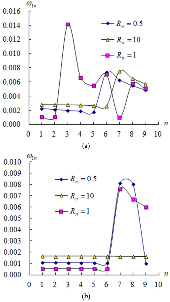
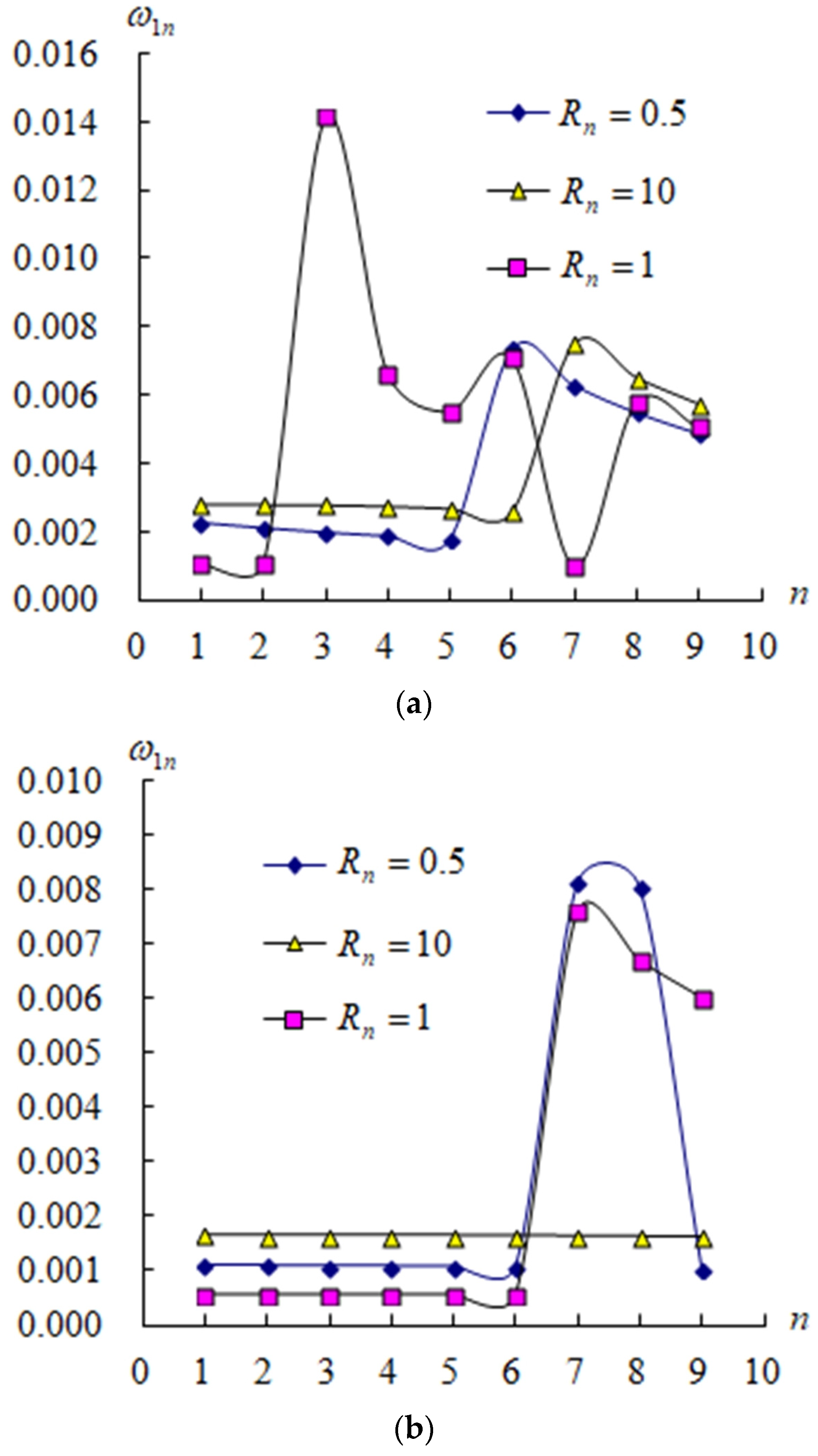
The values of dimensional for = 1 and = 1 to 9 vs. and (K) are presented for SUS304/Si3N4. Figure 2 displays the (1/s) vs. for = 5, 10, , advanced , = 0.925925/mm2 under = 300 K. Usually for thick-walled = 5 in Figure 2a, the values are oscillating with , versus = 1; the values are almost constant firstly, increasing then decreasing with , versus = 0.5 and 10; the maximum = 0.014121/s is obtained for = 1. Thus, the values are affected by or = 5. For moderately thick-walled = 10 in Figure 2b, the values are constant with , versus = 10; the values are a lower constant with from 1 to 6, increasing then decreasing, versus = 0.5 and 1; the maximum = 0.008109/s is obtained for = 0.5. Thus, the values are also affected by or = 10.
Figure 2.
(1/s) vs. under = 300 K for: (a) = 5; (b) = 10.
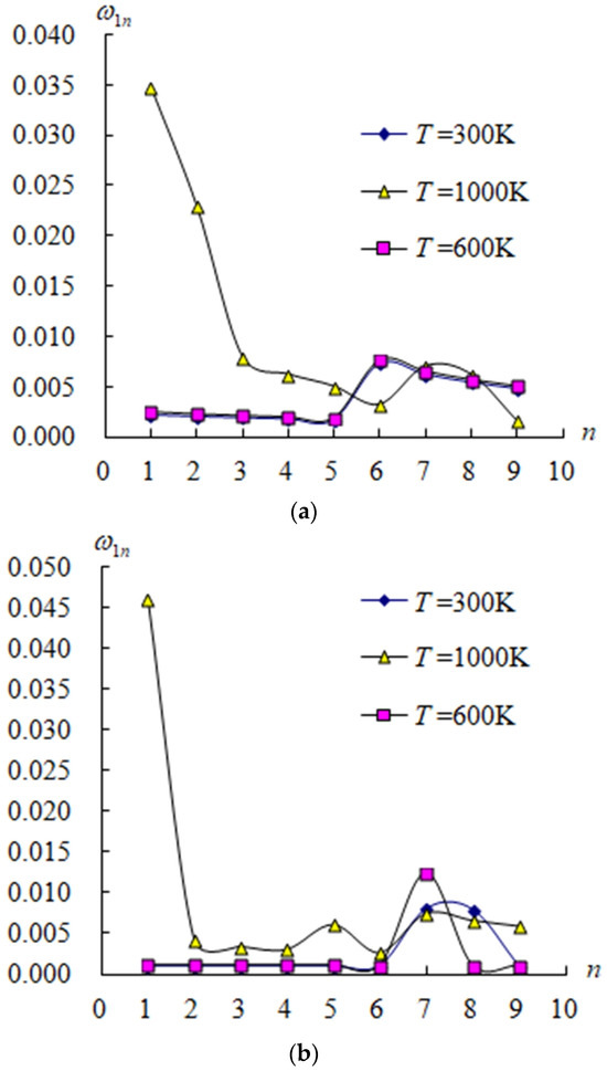
Figure 3 displays the (1/s) vs. for = 5, 10, , advanced , = 0.925925/mm2 and = 0.5. Usually for thick-walled = 5 in Figure 3a, the values are constant with from 1 to 5, increasing with from 5 to 6 versus = 300 K and 600 K, but decreasing with from 1 to 6 versus = 1000 K; the maximum = 0.034761/s is obtained for = 1000 K. Thus, the and values have the endurance ability on higher environment-temperature 1000 K for = 5. For moderately thick-walled = 10 in Figure 3b, the values are constant with from 1 to 6 versus = 300 K and 600 K; the maximum = 0.046005/s is obtained for = 1000 K. Thus, the value has the endurance ability in a higher environment-temperature of 1000 K for = 10.
Figure 3.
(1/s) vs. (K) for: (a) = 5; (b) = 10.
4. Discussions
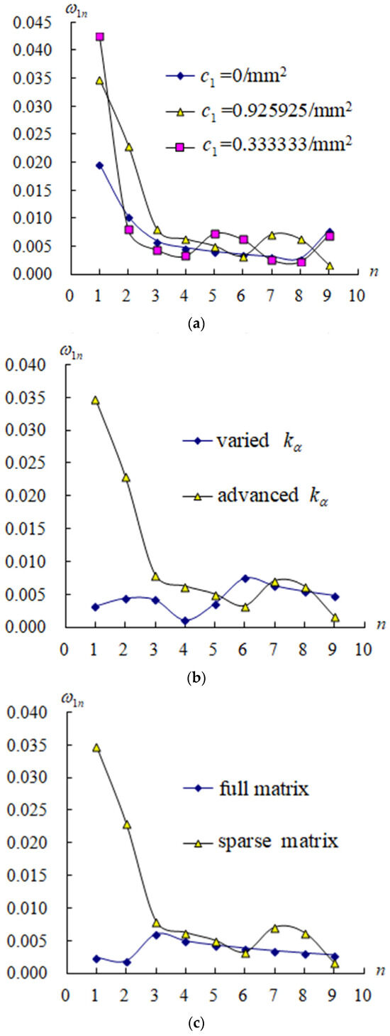
The variation of natural frequency compared (1/s) with respect to and requires further clarification on , = 5, = 0.5, T = 1000 K are displayed in Figure 4. The effects of value are displayed in Figure 4a for , values are decreasing for n = 1 to 6, values on = 0.925925/mm2 are greater than on = 0/mm2 for n = 1 to 8, values on = 0.333333/mm2 are greater than on = 0.925925/mm2 for n = 1 and oscillate close on = 0/mm2 for n = 2 to 9. The effects of value are displayed in Figure 4b for values on advanced [21] are greater than on varied [20] for n = 1 to 5, and the values are in sinusoidal oscillating on varied case. Basically, the values of advanced [21] are mainly functions of material properties , , , T, which are primarily from stiffness redistribution, but not a function of which is from a thickness-wise examination of the strain energy approach, and which is from a correction associated with the assumed kinematic TSDT model. The values of varied [20] are mainly functions of material properties , , , T, and , but not a function of .
Figure 4.
Compared (1/s) for: (a) = 0/mm2, = 0.333333/mm2, and = 0.925925/mm2; (b) advanced [21] and varied [20]; (c) sparse matrix and full matrix [20].
Thus, when = 0/mm2 is used, the structure behaves classically for FSDT, whereas when ≠ 0 is used, e.g., = 0.333333/mm2 on = 2 mm and = 0.925925/mm2 on = 1.2 mm dominate the size effects for TSDT. There is a critical temperature, e.g., greater than 600 K or a thickness ratio, e.g., less than 10 for a thick-walled study where local effects become not negligible due to thermal effects for FGMs. The dependence of on higher mode numbers (m,n ≤ 9) results in very low frequency values. This free vibration behavior is physically expected for thick-walled spherical FGM shells in the given typically sinusoidal displacements and shear rotations. The numerical truncation effects involved in the compared descriptions are displayed in Figure 4c with a presented simple homogeneous equation in a symmetrical sparse matrix (12) and a fully homogeneous equation in a symmetrical full matrix [20]. The assumed simplification in the sparse matrix causes a numerical truncation error, e.g., a large different value occurs at n = 1 and 2; the values of the presented sparse matrix are greater than those in the full matrix. The variation of natural frequency compared , with respect to value on , = 0.925925/mm2, = 0.5, 1, 10, T = 300 K are displayed in Figure 2. For = 5, it is displayed in Figure 2a, and for = 10, it is displayed in Figure 2b due to the power function of Young’s modulus in the expression for FGMs [21]. This dominates thickness and affects bending-shear coupling for data with = 10 showing slightly lower frequencies than = 5. In Figure 3a, the frequency increases with moderate temperatures T = 600 K but decreases at T = 1000 K. The physical phenomenon causes this trend reversal at high temperature due to the individual temperature-natural material property , e.g., , , etc. are expressed in , in which , , , , and denote coefficients of temperature for FGMs [20]. The values of advanced expression in (6) are non-dimensional and nonlinear and functions of , , and , but are not functions of for thick-walled FGMs [22]. The physical meaning of advanced is used to obtain an auto-calculation adjustment value rather than an assumed constant positive value for the transverse stiffness and transverse shear stress. Thus behaves unusually, e.g., > 1 or < 0 due to the given values of , , and . There are many key parameters studied in the applied mathematical simulation for the FGM spherical shell structure under numerical free vibration. In theory and simulation go first, this is why certain parameters, e.g., advanced shear correction, temperature, and power-law index = 0.1 are closely related to ceramic Si3N4; = 10 is closely related to metal SUS304, which leads to the influence on increases or decreases in natural frequencies by solving the homogeneous equation in a sparse matrix or a full matrix.
In particular, it is interesting in the related works on nonlinear vibration in 2025 by Putranto et al. [25] and equivalent single-layer (ESL) modeling in 2024 by Putranto [26] to discuss the broader context of advanced structural dynamics. A brief comparison of modeling philosophy and applicability would be valuable if possible in the future. A numerical flowchart summarizing the modeling steps, assumptions, and solution procedure to improve readability is displayed in Figure 5. The comparisons with selected published results would show more agreement in the exact choice of benchmark studies, e.g., FGM type, value, value, sparse matrix, and full matrix. If possible, one further comparison with an ESL-based solution would be more confidence in the future.
Figure 5.
A numerical flowchart.
5. Conclusions
The parameters of dimensional natural frequency and non-dimensional frequency, respectively, on and are presented with the simply symmetrical sparse matrix of thick-walled FGM spherical shells subjected to free vibration. Four main effects on frequency values are considered. They are the advanced shear coefficient, the nonlinear TSDT term of displacements, the FGM power law index, and the environment temperature. The novel and important numerical results are obtained in the following: the frequency parameters , data are presented and subjected to effect; the natural frequency data vs. and subjected to mode-shape number , are computed; the frequency values are studied for thick-walled FGM SUS304/Si3N4 spherical shells by using advanced . This is a new finding, as the assumed simplification in a sparse matrix causes a numerical truncation error; the values at n = 1 and 2 of the presented sparse matrix are much greater than those in the full matrix for thick-walled FGM spherical shells.
Funding
This research received no external funding.
Data Availability Statement
The original contributions presented in the study are included in the article; further inquiries can be directed to the corresponding authors.
Acknowledgments
The author expresses his thanks to the people helping with this work and acknowledges the valuable suggestions from the peer reviewers.
Conflicts of Interest
The author declares no conflicts of interest.
Abbreviations
The following symbols and abbreviations are used in the nomenclature list for this manuscript:
| FGM | Functionally Graded Material |
| FGMs | Functionally Graded Materials |
| FG-GPLRC | Functionally Graded Graphene Platelets Reinforced Composite |
| FGPSS | Functionally Graded Porous Spherical Shell |
| CSCS | Combined Spherical-Cylindrical-Spherical |
| CFRP | Carbon Fiber-Reinforced Polymer |
| GFRP | Glass Fiber Reinforced Plastic |
| FSDT | First-order Shear Deformation Theory |
| TSDT | Third-order Shear Deformation Theory |
| HSDT | Higher-order Shear Deformation Theory |
| HOZT | Higher Order Zigzag Theory |
| PET | Plane-Elasticity Theory |
| PDE | Partial Differential Equation |
| ESL | Equivalent Single-Layer |
| 2D | Two-Dimensional |
| 3D | Three-Dimensional |
| (x, y, z) | A point in Cartesian axes x, y, z |
| Radius | |
| Circumferential angle | |
| axis | |
| Displacements in x axis, y axis, z axis | |
| axes of the middle-plane of shells | |
| axis of the middle-plane of shells | |
| x axial length of shells | |
| , Nonlinear TSDT term of z3 | |
| , Total thickness of shells | |
| Inner layer thickness | |
| Outer layer thickness | |
| axes of the middle-plane of shells | |
| Middle-surface radius of shells | |
| t | Time |
| , | |
| Shear correction | |
| Young’s modulus on FGM constituent materials 1 and 2 | |
| Density on FGM constituent material 1 | |
| Power law index | |
| Coefficients of temperature for FGM constituent material | |
| Environment-temperature | |
| Temperature-difference | |
| In-plane distributed forces | |
| External pressure load | |
| External loads | |
| Amplitudes of sinusoidal displacements and shear rotations | |
| Free vibration frequency with subscripts m, n denote mode shape number | |
| , i = 0, 1, 2,…, 6 | |
| Density of the (k)th ply | |
| , i = 1, 4 | |
| Total number of layers | |
| Length to thickness ratio | |
| Length to radius ratio | |
| Non-dimensional frequency, | |
| Non-dimensional frequency, |
Appendix A
The coefficients in Equation (12) are listed as follows,
The coefficients in Equation (13) are listed as follows,
in which
References
- Bagheri, H.; Kiani, Y.; Eslami, M.R. Free vibration of FGM conical–spherical shells. Thin-Walled Struct. 2021, 160, 107387. [Google Scholar] [CrossRef] [Scilit]
- Liu, D.; Zhou, Y.; Zhu, J. On the free vibration and bending analysis of functionally graded nanocomposite spherical shells reinforced with graphene nanoplatelets: Three-dimensional elasticity solutions. Eng. Struct. 2021, 226, 111376. [Google Scholar] [CrossRef] [Scilit]
- Tang, H.; Dai, H.L. Nonlinear vibration analysis of CFRP spherical shell panel under hygrothermal effects. Compos. Struct. 2021, 274, 114343. [Google Scholar] [CrossRef] [Scilit]
- Roy, S.; Thakur, S.N.; Ray, C. Free vibration analysis of laminated composite hybrid and GFRP shells based on higher order zigzag theory with experimental validation. Eur. J. Mech. A Solids 2021, 88, 104261. [Google Scholar] [CrossRef] [Scilit]
- Sayyad, A.S.; Ghugal, Y.M. Static and free vibration analysis of laminated composite and sandwich spherical shells using a generalized higher-order shell theory. Compos. Struct. 2019, 219, 129–146. [Google Scholar] [CrossRef] [Scilit]
- Li, H.; Cong, G.; Li, L.; Pang, F.; Lang, J. A semi analytical solution for free vibration analysis of combined spherical and cylindrical shells with non-uniform thickness based on Ritz method. Thin-Walled Struct. 2019, 145, 106443. [Google Scholar] [CrossRef] [Scilit]
- Li, H.; Pang, F.; Ren, Y.; Miao, X.; Ye, K. Free vibration characteristics of functionally graded porous spherical shell with general boundary conditions by using first-order shear deformation theory. Thin-Walled Struct. 2019, 144, 106331. [Google Scholar] [CrossRef] [Scilit]
- Fantuzzi, N.; Brischetto, S.; Tornabene, F.; Viola, E. 2D and 3D shell models for the free vibration investigation of functionally graded cylindrical and spherical panels. Compos. Struct. 2016, 154, 573–590. [Google Scholar] [CrossRef] [Scilit]
- Sepiani, H.A.; Rastgoo, A.; Ebrahimi, F.; Arani, A.G. Vibration and buckling analysis of two-layered functionally graded cylindrical shell considering the effects of transverse shear and rotary inertia. Mater. Des. 2010, 31, 1063–1069. [Google Scholar] [CrossRef] [Scilit]
- Zannon, M.; Abu-Rqayiq, A.; Al-bdour, A. Free vibration analysis of thick FGM spherical shells based on a third-order shear deformation theory. Eur. J. Pure Appl. Math. 2020, 13, 766–778. [Google Scholar] [CrossRef] [Scilit]
- Keibolahi, A.; Kiani, Y.; Eslami, M.R. Nonlinear dynamic snap-through and vibrations of temperature-dependent FGM deep spherical shells under sudden thermal shock. Thin-Walled Struct. 2023, 185, 110561. [Google Scholar] [CrossRef] [Scilit]
- Khoa1, N.M.; Tung, H.V. Nonlinear thermo-mechanical stability of shear deformable FGM sandwich shallow spherical shells with tangential edge constraints. Vietnam J. Mech. 2017, 39, 351–364. [Google Scholar] [CrossRef] [Scilit]
- Zhang, Z.; Feng, Z.; Shi, Z.; Xie, H.; Sun, Y.; Gu, Z.; Xiao, J.; Xu, J. Static analysis of temperature-Dependent FGM spherical shells under thermo-mechanical loads. Buildings 2025, 15, 2709. [Google Scholar] [CrossRef] [Scilit]
- Nejad, M.Z.; Abedi, M.; Alavi, N. Elastic analysis of FGM solid sphere with parabolic varying properties. J. Comput. Appl. Mech. 2026, 57, 1–10. [Google Scholar]
- Dastjerdi, S.; Malikan, M.; Eremeyev, V.A.; Akgöz, B.; Civalek, Ö. On the generalized model of shell structures with functional cross-sections. Compos. Struct. 2021, 272, 114192. [Google Scholar] [CrossRef] [Scilit]
- Arslan, E.; Mack, W. Sensitivity of predicted stresses in thick-walled steel/ceramics spherical FGM-structures to parameter uncertainties. Proc. Appl. Math. Mech. 2022, 22, 1. [Google Scholar] [CrossRef] [Scilit]
- Khaire, P.; Ambhore, N.; Jagtap, K.R. Nonlinear free vibration analysis of functionally graded materials spherical shell using higher order shear deformation theory. Int. J. Eng. Res. Tech. 2014, 3, 3. [Google Scholar]
- Zeverdejani, P.K.; Kiani, Y. Radially symmetric response of an FGM spherical pressure vessel under thermal shock using the thermally nonlinear Lord-Shulman model. Int. J. Pres. Vessel. Pip. 2020, 182, 104065. [Google Scholar] [CrossRef] [Scilit]
- Shariyat, M.; Ghafourinam, M. Hygrothermomechanical creep and stress redistribution analysis of thick-walled FGM spheres with temperature and moisture dependent material properties and inelastic radius changes. Int. J. Pres. Vessel. Pip. 2019, 169, 94–114. [Google Scholar] [CrossRef] [Scilit]
- Hong, C.C. Free vibration frequency of thick FGM spherical shells with simply homogeneous equation by using TSDT. J. Braz. Soc. Mech. Sci. Eng. 2020, 42, 159. [Google Scholar] [CrossRef] [Scilit]
- Hong, C.C. Advanced frequency of thick FGM cylindrical shells with fully homogeneous equation. J. Struct. Eng. Appl. Mech. 2024, 7, 69–83. [Google Scholar] [CrossRef] [Scilit]
- Hong, C.C. Advanced dynamic responses of thick FGM spherical shells analyzed using TSDT under thermal vibration. Computation 2025, 13, 245. [Google Scholar] [CrossRef] [Scilit]
- Conte, S.D.; de Boor, C. Elementary Numerical Analysis, an Algorithmic Approach, 3rd ed.; McGraw-Hill Book Company: New York, NY, USA, 1980. [Google Scholar]
- Li, H.; Pang, F.; Miao, X.; Gao, S.; Liu, F. A semi analytical method for free vibration analysis of composite laminated cylindrical and spherical shells with complex boundary conditions. Thin-Walled Struct. 2019, 136, 200–220. [Google Scholar] [CrossRef] [Scilit]
- Putranto, T.; Yulianto, T.; Sujiatanti, S.H.; Setyawan, D.; Zakki, A.F.; Alie, M.Z.M.; Wibowo, W. Numerical analysis of composite stiffened NiTiNOL–Steel wire ropes and panels undergoing nonlinear vibrations. Modelling 2025, 6, 77. [Google Scholar] [CrossRef] [Scilit]
- Putranto, T. Equivalent single layer approach for ultimate strength analysis of box girder under bending load. Ocean Eng. 2024, 292, 116535. [Google Scholar] [CrossRef] [Scilit]



Disclaimer/Publisher’s Note: The statements, opinions and data contained in all publications are solely those of the individual author(s) and contributor(s) and not of MDPI and/or the editor(s). MDPI and/or the editor(s) disclaim responsibility for any injury to people or property resulting from any ideas, methods, instructions or products referred to in the content. |
© 2026 by the author. Licensee MDPI, Basel, Switzerland. This article is an open access article distributed under the terms and conditions of the Creative Commons Attribution (CC BY) license.