


Abstract
We studied the Stokes signals generated following the Raman photoexcitation of dissolved oxygen in water. When a water sample is pumped with intense nanosecond radiation, Stokes signals of different origins are generated. These signals form a characteristic nonlinear diffraction pattern, comprising a central spot and concentric rings whose radii depend on the Stokes wavelengths. Although most of the Stokes signals correspond to the stretching vibrations of water molecules, we also observed a small contribution from dissolved oxygen molecules. This contribution can be separated from the others using appropriate spectroscopic filters, then analyzed with a spectrometer. In this study, we report on Stokes components assigned to singlet oxygen excitation detected in the central spot, as well as in the diffraction pattern’s ring structure. The signal detected in the central spot exhibits a single peak, while that from the ring shows a two-peak structure. These two observed peaks are interpreted as Stokes signals corresponding to Raman transitions to the two lowest vibrational sublevels of the singlet-oxygen electronic state. We also report exponential growth in the Stokes signal with the pulse energy, in agreement with the standard stimulated Raman theoretical model.
1. Introduction
Singlet oxygen (1O2) is a reactive oxygen species (ROS) widely used in photochemistry, photobiology, and photomedicine [1,2,3,4,5,6], which corresponds to the lowest excited electronic level of the oxygen molecule. 1O2 excitation via direct photon absorption is not effective, as the dipolar transition from the ground to the 1O2 state is heavily forbidden by quantum mechanics selection rules. As such, photosensitizing is the commonly used 1O2 excitation method [7,8]. A large molecule that can absorb visible photons stores part of the absorbed energy in a metastable triplet state; this energy can then be transferred to oxygen molecules, thereby exciting 1O2. We previously reported a new Raman-based, photosensitizer-free method for 1O2 photoexcitation [9,10,11,12], in which a pumping photon generates a Stokes photon of lower energy, inducing the transition from the ground state to the 1O2 level. The energy difference between the two photons corresponds to the 1O2 energy level. We demonstrated that the observed Stokes signal was oxygen-dependent by reducing the oxygen concentration with an oxygen quencher such as sodium bisulfite (NaHSO3), increasing the sample temperature, or purging the solvent with argon [9]. We also showed that the signal’s wavelength was the same across different solvents, demonstrating its solvent independent nature. Furthermore, we assessed the Raman character of the observed 1O2 Stokes signal by measuring its wavelength shift as the pump wavelength was varied, and showing its temporal coincidence with the pump pulse [10]. We reported that the 1O2 Stokes’ signal exhibited a diffraction pattern with a central spot and a system of rings, characteristic of a stimulated Raman process [10,13]. We also reported the 1O2 phosphorescence at 1270 nm, which is typically observed upon excitation of the 1O2 state [11]. More recently, we determined the efficiency of the abovementioned 1O2 Raman photoexcitation process [12].
When performing the previous experiments, we noted that Stokes signals corresponding to the solvent’s vibrational modes overlap with the 1O2 Stokes signal in both parts of the diffraction pattern, making their detection difficult. However, Stokes photons from water typically have lower energy than those from 1O2, allowing the contributions to be separated using long-pass spectroscopic filters. Furthermore, the oxygen Stokes peaks are of electronic origin and exhibit a spectral width on the order of tens of nanometers, while the solvent Stokes peaks have a spectral width that is an order of magnitude smaller [9]. These differences help to identify peaks and separate them from one another. In this work, we present evidence for two other remarkable characteristics of the 1O2 Stokes signal that have not been reported previously. First, we provide spectroscopic evidence regarding the contribution of the vibrational structure of the 1O2 electronic level. Second, we show that the 1O2 Stokes signal grows exponentially with the pulse energy.
The spectral response of the lowest electronic levels of molecular oxygen has been studied in detail for over a century. Analyzing the atmospheric absorption of solar radiation, Herzberg reported peaks at 1268 and 1067 nm [14,15], which were assigned to absorption bands corresponding to transitions from the ground state to the two lowest vibrational modes of the 1O2 state. These results were confirmed in Ellis and Kneser’s study of the absorption of light by liquid oxygen [16]. Details of molecular oxygen spectra were further discussed in later reviews [17,18], while more recent studies have reported the same spectral absorption peaks for molecular oxygen dissolved in solvents [19,20,21]. Here, we demonstrate that examining the spectral properties of the Raman diffraction pattern provides insight into the Raman photoexcitation of oxygen molecules. In particular, we observed Stokes components corresponding to excitation of the two lowest vibrational sublevels of the 1O2 state, which is in agreement with previous absorption studies. This study’s novelty lies in the fact that the peaks are Stokes signals in the visible spectrum, generated during the excitation of molecular oxygen via a stimulated Raman process. The presence of both peaks confirms that the reported Stokes signals originate from oxygen, as only the oxygen molecule can induce such a spectral response.
The basic theory of stimulated Raman scattering predicts exponential gain in Stokes signals [22,23,24,25], which is the fundamental idea underlying the development of Raman fiber lasers, Raman sensors, and highly sensitive Raman spectroscopy techniques [26,27,28,29]. The exponential gain in the Stokes signals due to Raman 1O2 photoexcitation observed in this study confirms the basic predictions of standard stimulated Raman excitation theory. These results may impact the design of methods and instrumentation to improve 1O2 photosensitizer-free excitation using the Raman approach.
2. Theoretical Considerations
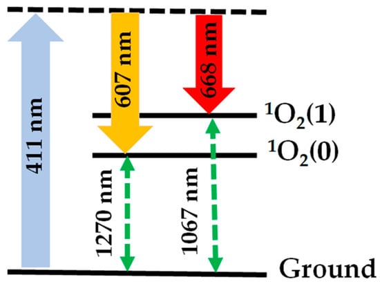
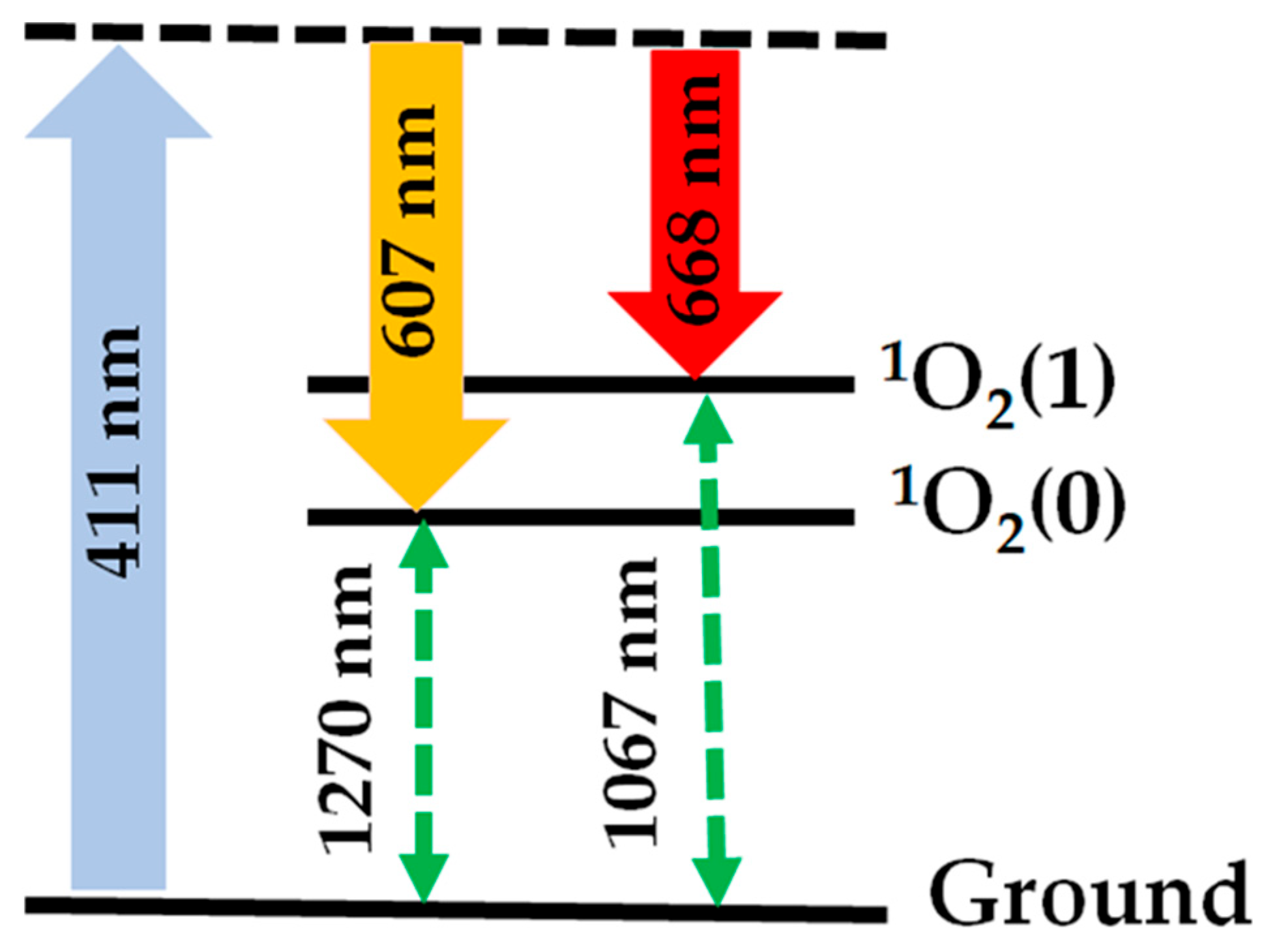
Figure 1 shows the schematic of the first two vibrational sublevels, 1O2(0) and 1O2(1), of the 1O2 electronic state, as established in the studies cited above. 1O2(0) lies 0.97 eV from the ground, which corresponds to the energy of a photon with a wavelength of 1270 nm. 1O2(1) is at 1.16 eV, which corresponds to the energy of a photon with a wavelength of 1067 nm. Both states have rotational sub-levels that are not indicated in the figure. Raman excitation generates Stokes signals for these two levels; for example, when pumping at 411 nm, Stokes signals at 607 and 668 nm are expected. Anti-Stokes components are also generated in the ultraviolet (UV) region of the spectrum, but this contribution is generally small for the pulse energies used in the present experiments.
Figure 1.
Schematic of Raman excitation of the two lowest vibrational levels of the 1O2 electronic state. When pumping at 411 nm, Stokes components at 607 nm and 668 nm are generated.
Stimulated Raman scattering refers to the interaction between Stokes and anti-Stokes photons and matter. The basic theory of the effect states that there are two kinds of stimulated Raman scattering signals: one set of signals propagates in the direction of the excitation beam, and another set propagates at an angle with respect to this direction [24,25]. As a result, the stimulated Raman interaction-induced diffraction pattern shows a central spot and concentric rings [14].
As discussed above, theoretical models of stimulated Raman scattering indicate that the Stokes signal experiences exponential gain, whereas the anti-Stokes beam exhibits losses [25]. In Appendix A we present the calculated gain values (see Equation (A5)), which quantify the signal’s growth as a function of the pump pulse energy.
The Raman diffraction pattern ring’s structure corresponds to the phase-matching condition given by the following equation [13]:
where , , and are the wavevectors of the pump, Stokes, and anti-Stokes fields, respectively, , , and are the pump, Stokes, and anti-Stokes wavelengths, respectively, , , and are the refraction indices at , , and , respectively, and , , and are the unit wave-vectors of the pump, Stokes and anti-Stokes beams, respectively.
The values of and are calculated from their definition and , where are the wavelengths corresponding to the transitions from the ground to the quantum levels 1O2(0) and 1O2(1).
In Appendix B, we describe the procedure for estimating the deviation angles of the beams that form the ring structure. Notably, nonlinear Raman diffraction effects such as self-focusing are not included in this simplified model, which may affect the final deviation values [13]. As indicated by Equation (1), the radii of the rings depend on the wavelength of each of the fields; thus, the procedure for separating and identifying different Stokes components becomes less cumbersome. In the Experimental Section, we take advantage of this fact, allowing us to identify the Stokes signals corresponding to the Raman transition to the 1O2 electronic state vibrational sublevels (0) and (1).
3. Materials and Methods
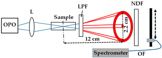
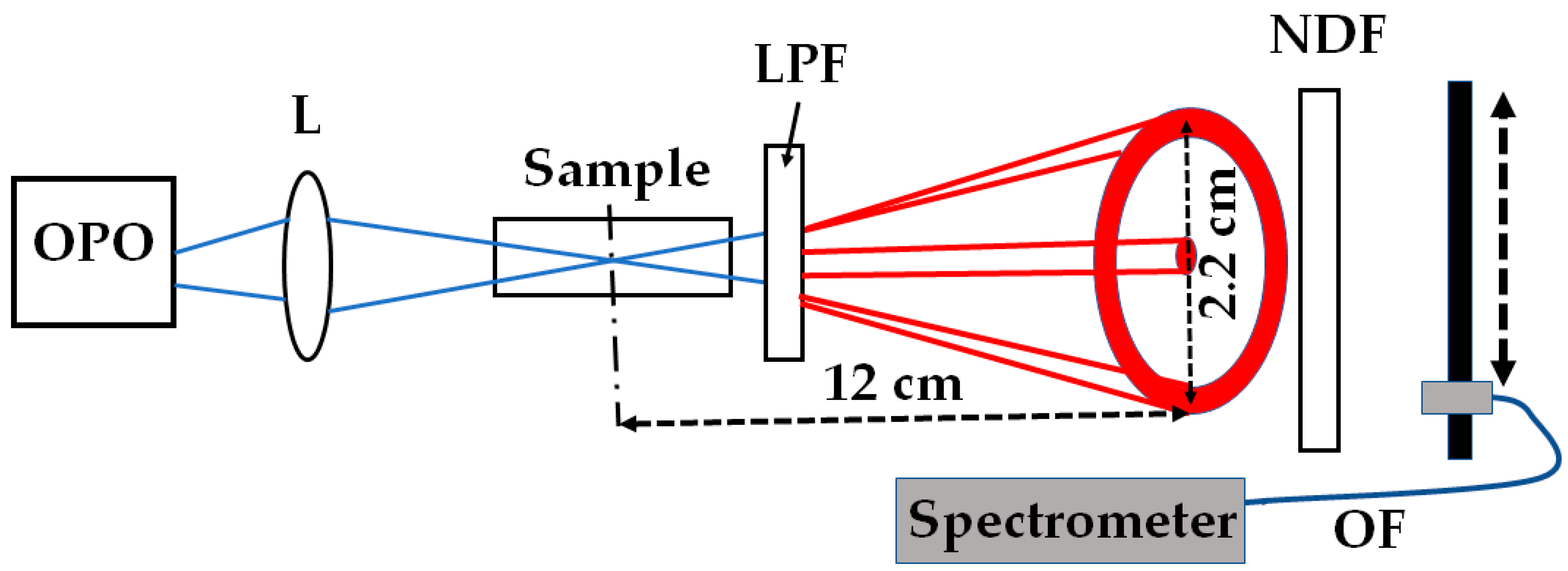
Figure 2 shows a schematic of the experimental setup. An optical parametric oscillator (OPO, OPOTEK, Carlsbad, CA, USA) provided the pump beam. We used a pump wavelength of 411 nm. The device generated 5-nanosecond pulses with a pulse energy of around 20 mJ. A lens with a 20 cm focal length focused the pumping light onto the sample. We estimated a waist beam radius of 5.2 μm and a Rayleigh range of 0.02 cm. The sample was distilled water in a glass cuvette with a path length of 20 cm.
Figure 2.
Schematic of experimental setup showing the optical parametric oscillator (OPO), the focusing lens (L), the glass cuvette containing water (Sample), the long-pass filter (LPF), the neutral-density filter (NDF), an optical fiber (OF, dark blue line), and a spectrometer. A schematic of the Raman diffraction pattern is shown in red. The pump beam is shown in blue. The distances between the pump focal plane and the observation plane is indicated, as well as the ring diameter.
A long-pass filter (LPF) with a cut-off wavelength of 600 nm was used to select light matching the 1O2 Stokes contribution. The filter removed all Stokes contributions from the solvent molecules, leaving only those from dissolved oxygen molecules [9,10]. As a result, a red-colored Raman diffraction pattern with a central spot and a ring appeared at the cuvette’s exit. A neutral-density filter (NDF) was used to control the intensity of this light and prevent saturation of the detection system.
The pattern was analyzed using a spectrometer (Ocean Optics USB 2000, Orlando, FL, USA) connected to an optical fiber (OF). The instrument averaged 100 spectra. We placed the optical fiber’s entrance coupler 12 cm from the pump waist position. At that distance, the ring’s radius was about 11 mm. The coupler’s entrance diameter was 1 mm.
We collected spectra from different parts of the diffraction pattern by scanning the fiber’s coupler along the center of the pattern in 1 mm steps. We also measured the signals’ dependence on pump energy at the central spot and the ring using a diode detector (DET100 A2, Thorlabs, Newton, NJ, USA). The detector sent the signal to a digital oscilloscope (TDS 3052, Tektronix, Beaverton, OR, USA) for averaging and monitoring, with the resulting signal corresponding to an average of 512 pulses. A reference detector (not shown in Figure 2) triggered the oscilloscope. We varied the pump energy by placing neutral-density filters with optical densities from 0.1 to 1.9 in front of the cuvette. The pump pulse energy was calibrated using a pulse energy detector (Pulsar-1, Newport Corporation, Ophir, North Logan, UT, USA), which averaged the energy of 500 pulses, providing a standard deviation of about 10%.
4. Results and Discussion
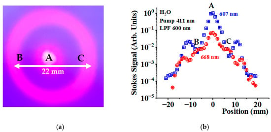
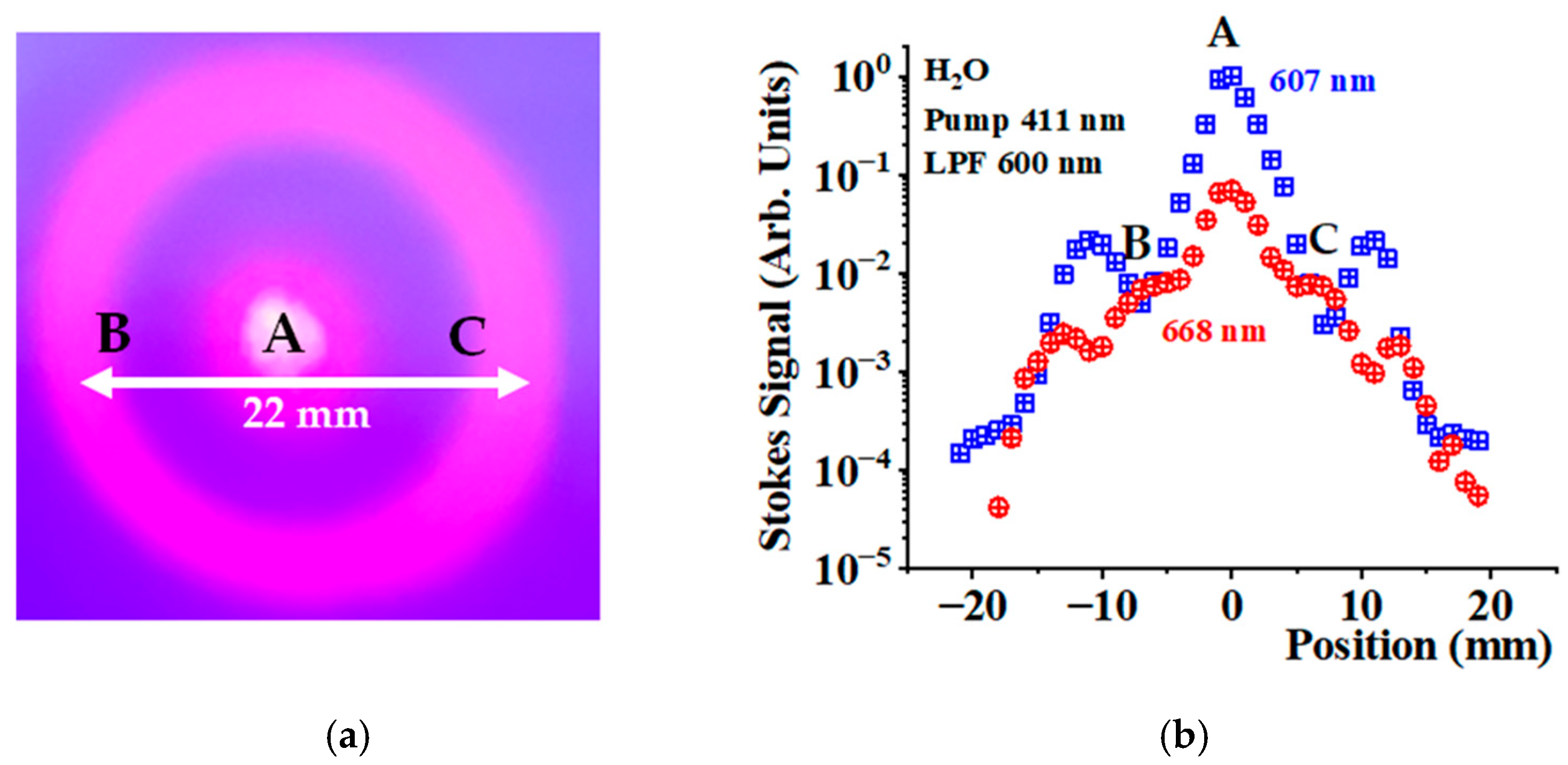
Figure 3a shows a photograph of the diffraction pattern observed when pumping at 411 nm and using a long-pass filter with a cut-off wavelength of 600 nm, in the which the central spot and the ring structure can be seen. Our previous experiments have demonstrated that the observed signal corresponds to the Stokes signal generated by Raman excitation of oxygen toward the 1O2 level [9,10,11,12].
Figure 3.
(a). Raman diffraction pattern observed at a distance of 12 cm from the pump waist when pumping at 411 nm and using an LPF with a cut-off wavelength of 600 nm. (b) Stokes signal amplitudes at 607 nm (blue crossed squares) and 668 nm (red crossed circles) as a function of position in the Raman diffraction pattern. The points indicated by the letters A, B, and C are the same in both figures.
Using the spectrometer, we collected spectra along the direction indicated by the white arrow as we scanned the optical fiber coupler with 1 mm steps. For each spectrum, we determined the Stokes signal amplitude as a function of the positions at 607 and 668 nm.
Figure 3b shows this relationship on a semi-logarithmic scale. The blue-crossed squares correspond to the signals at 607 nm, while the red-crossed circles refer to those at 668 nm. The signals at 668 nm are generally smaller than those at 607 nm, particularly for the central spot (point A). At some points on the ring—indicated by B and C- the signals become comparable. From the figure, it can be seen that the ring radii depend slightly on wavelength, allowing for the separation of Stokes components with slightly different wavelengths.
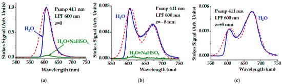
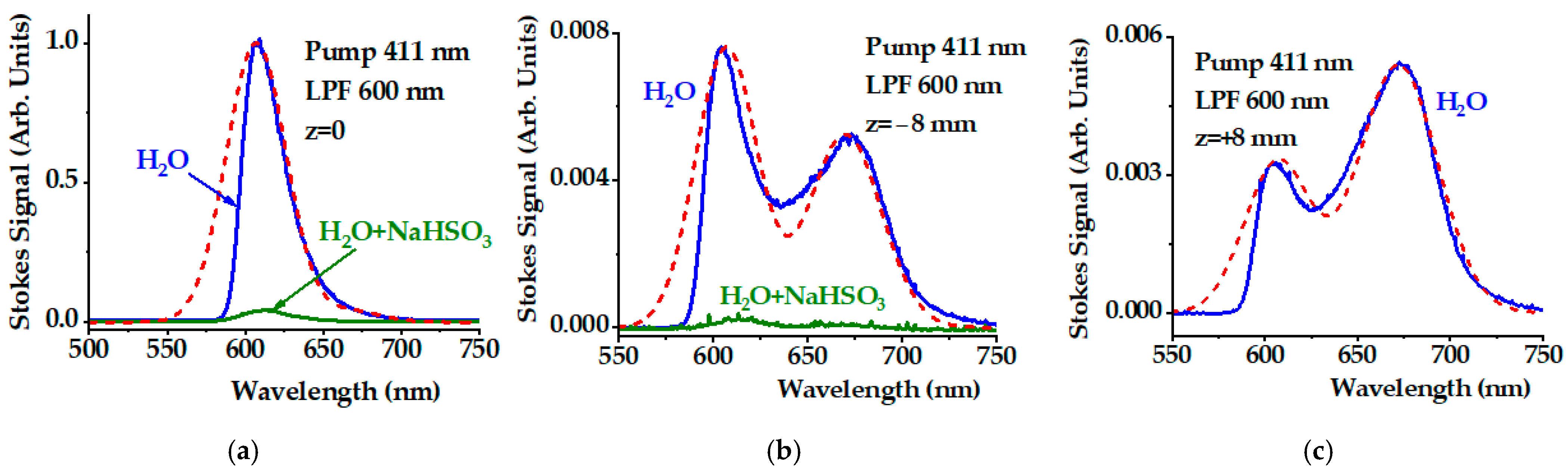
Figure 4 shows the spectra measured at points A, B, and C (Figure 4a, Figure 4b, and Figure 4c, respectively). All signal amplitudes are given in the same arbitrary units. The signal at point A is more than two orders of magnitude larger than those at B and C. The most important feature is that the central spot exhibits a single peak around 607 nm, whereas those at B and C show a double-peak structure with peaks around 607 and 668 nm. These spectra confirm the generation of Stokes signals corresponding to Raman transitions from the ground state to the 1O2(0) and 1O2(1) levels. Only the oxygen molecule can exhibit the double-peak response in the Stokes signal spectrum shown in Figure 4b,c. For the central spot, the contribution at 668 nm is more than one order of magnitude smaller than the Stokes signal at 607 nm. Some spectral asymmetry toward longer red wavelengths is evident in Figure 4a due to the contribution at 668 nm.
Figure 4.
(a) Stokes spectra collected at the central spot at position A (z = 0), and those at the ring positions (b) B (z = −8 mm), and (c) C (z = +8 mm) shown in Figure 3. The green curve in (a,b) is the signal after adding NaHSO3 at a concentration of 40 mg/mL. The red dashed lines represent the interpretation of the spectra as the sum of two Gaussians centered at 607 nm and 668 nm (see Table 1 for details). We used a pump wavelength of 411 nm and a long-pass filter with a cut-off of 600 nm.
To validate that the observed Stokes signal is oxygen-dependent, we added the oxygen quencher NaHSO3 to the water sample. The green lines in Figure 4a,b represent the same Stokes signal upon adding NaHSO3 up to a final concentration of 40 mg/mL. We measured the oxygen concentration using an optical sensor (LabQuest 2, Vernier, Beaverton, OR, USA). Adding NaHSO3 reduced the oxygen concentration from 8.5 mg/L to 0.6 mg/L. Both Stokes signals at 607 nm and 668 nm were significantly reduced (see Figure 4a,b), confirming that these peaks originate from oxygen.
The red dashed lines in Figure 4a–c correspond to the interpretation of the spectra as the sum of two Gaussians centered at 607 nm and 668 nm. These lines were calculated using the equation
where represents the predicted spectrum and is the signal’s wavelength (in nm). The values of the parameters and are given in Table 1.
Table 1.
Parameters used in the calculations of Equation (2).
The values of and are provided in the same arbitrary units. The values for the spectral widths and varied slightly. The signals shown in Figure 4b,c correspond to beams propagating at an angle with respect to the pump beam. As this angle depends on the wavelength, small changes in the spectral width may be expected. The lines are broad with an average full spectral width of 55 ± 8 nm. The width reflects the rotational structure of the electronic-vibrational lines, which are broadened by interactions with solvent molecules. The real spectra disagree with the model spectra at wavelengths below 600 nm. As the LPF partially depleted the signal below 600 nm, yielding the asymmetric spectra shown in Figure 4.
We calculated the angle of deviation following the procedure described in Appendix B using the parameters presented in Table 2; in particular, the wavelengths corresponding to the transition from the ground state to 1O2(0) and 1O2(1) predicted from the literature, the wavelengths of the Stokes and anti-Stokes components, and the expected angle of deviation of the Stokes components at 607 nm and 668 nm when pumping at 411 nm. We used Equation (A8) in Appendix B to calculate . The final column shows the actual deviations measured in the experiments. For the calculation, we used the refraction index values available from the literature [30].
Table 2.
Wavelength values corresponding to the transition from ground toward 1O2(0) and 1O2(1), , Stokes , anti-Stokes wavelengths, and predicted and measured values for the deviation of the 1O2 Stokes components at 607 nm and 668 nm ().
Although the model predicted a larger deviation angle for larger Stokes wavelengths, the measured deviation values were smaller than the predicted ones. As nonlinear Raman diffraction induces beam self-focusing, thereby reducing the deviation a more precise model that includes these effects is required to better validate the measured values.
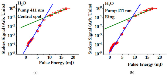
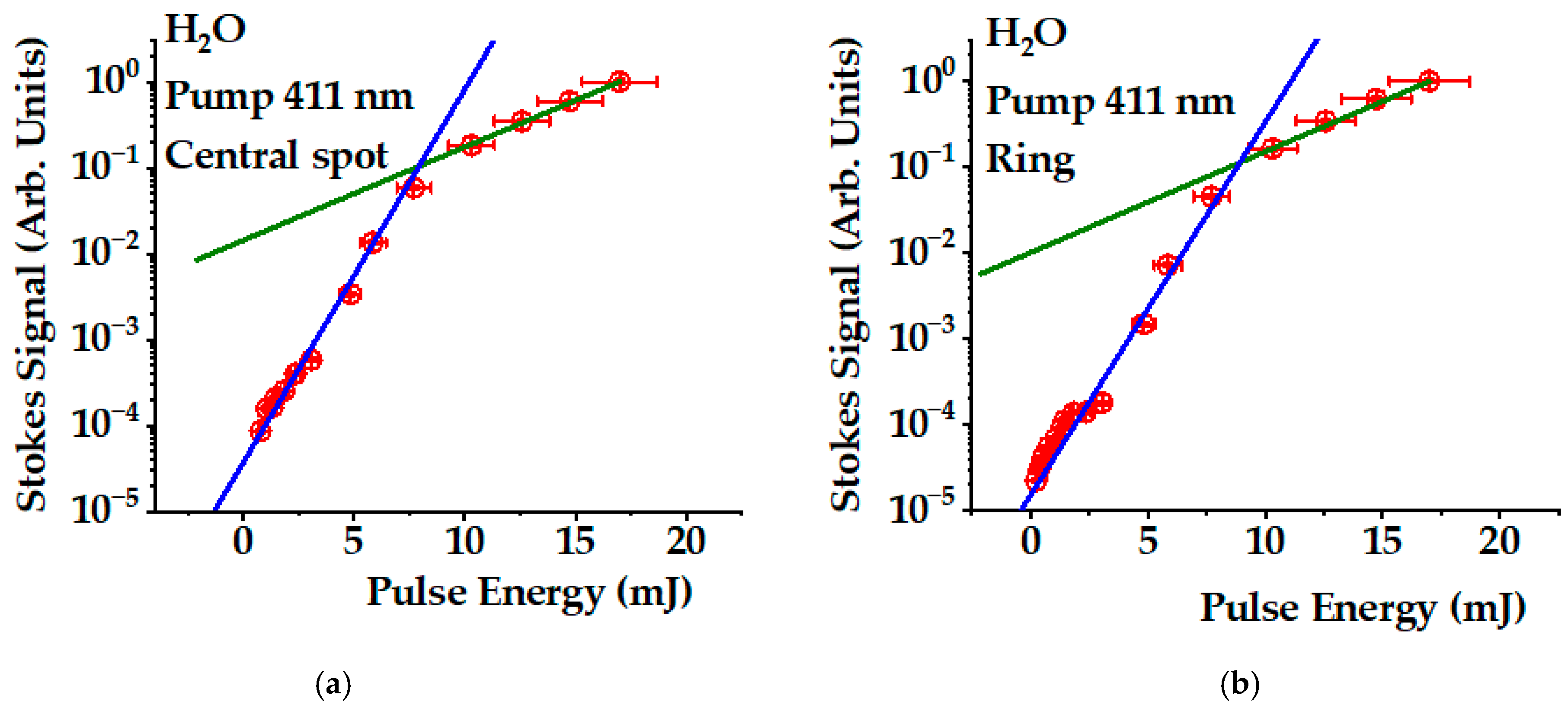
We also studied the dependence of the Stokes signal on the pump energy using a set of neutral-density filters to change the pump energy. Figure 5 shows this dependence on a semi-logarithmic scale measured for the central spot (Figure 5a) and the ring structure (Figure 5b). Both dependencies are similar: when the pulse energy changes by a factor of 20, the Stokes signal changes by 5 orders of magnitude, indicating exponential growth.
Figure 5.
Pump pulse energy dependence of Stokes signals in (a) the central spot and (b) the ring (red dots). We used a pump wavelength of 411 nm and a long-pass filter with a cut-off wavelength of 600 nm. The blue solid lines correspond to a simulation with an exponential gain of 1 mJ−1. The green solid line is a simulation with a gain of 0.25 mJ−1.
A reduction in exponential growth was observed for energies above 8 mJ. The blue solid lines in both, Figure 5a,b, correspond to an energy exponential gain of 1 mJ−1, while the green lines correspond to a gain of 0.25 mJ−1. At high intensity, the coupling between Stokes and anti-Stokes components increases. As the anti-Stokes components exhibit absorption, an additional loss channel for the Stokes component limits the gain. Furthermore, the pump field induces significant Stokes components from the solvent’s stretching modes [12]. At high intensity, pump depletion occurs mostly due to these losses. The interactions between the Stokes and anti-Stokes components have been discussed in detail in the literature [25]. Using Equation (A5), we determined the imaginary component of the 1O2 Raman susceptibility to be of (6.0 ± 0.5) × 10−23 m2 V−2 under the conditions of the present experiment.
5. Conclusions
We measured the Raman 1O2 photoexcitation spectra upon 411 nm pumping. As predicted by basic stimulated Raman excitation theory, we observed two kinds of Stokes signals. The first propagates in the direction of the pumping beam, forming a central spot in the Raman diffraction pattern, while the second contribution forms an angle with respect to the pump direction, thus creating a ring structure. We analyzed the spectral properties of the Raman diffraction pattern. The central spot exhibits a single-peak structure centered around 607 nm, corresponding to the transition from the ground to the 1O2(0) state. At some points of the ring structure, it becomes possible to detect a two-peak structure containing contributions at 607 nm and 668 nm, with the latter corresponding to the transition toward the 1O2(1) state. These results confirm the electronic vibrational structure of molecular oxygen predicted in previous studies [14,15,16,17,18]. The findings also demonstrate that studying the spectral properties of the Stokes ring structure is a suitable method for separating different Stokes contributions. This strategy represents a new approach for spectroscopic studies of complex Raman interactions.
We have provided evidence for the exponential growth in the Stokes signals, as predicted by early theoretical models of the stimulated Raman process. This result opens the possibility for designing new methods and Raman instrumentation to improve the efficiency of photosensitizer-free 1O2 Raman photoexcitation with intrinsic applications in photobiology, photochemistry, and photomedicine. We have previously demonstrated that it is possible to deactivate viruses using only blue light [31]. As the Raman effect is a fundamental physical phenomenon arising from the interaction of light with matter, the approach may have universal applicability for the possible deactivation of any kind of viruses, bacteria, or fungi.
Author Contributions
A.M.O.: conceptualization, methodology, validation, data collection, formal analysis, writing, review and editing, funding acquisition and administration. W.R.: validation, data collection, formal analysis, and investigation. S.W.: validation, data collection, formal analysis, and investigation. All authors have read and agreed to the published version of the manuscript.
Funding
The research was sponsored by the Air Force Office of Scientific Research and was accomplished under grant number W911NF-23-1-0245. The views and conclusions are those of the authors and should not be interpreted as representing the official policies, either expressed or implied, of the Air Force Office of Scientific Research or the US Government. The US Government is authorized to reproduce and distribute reprints for Government purposes, notwithstanding any copyright notation herein.
Institutional Review Board Statement
Not applicable.
Informed Consent Statement
Not applicable.
Data Availability Statement
The raw data supporting the conclusions of this article will be made available by the authors on request.
Acknowledgments
During the preparation of this manuscript, the authors used the “Grammarly Pro for Windows” software for editing purposes. We also used MDPI editing services for the same purpose. The authors have reviewed and edited the output and take full responsibility for the content of this publication.
Conflicts of Interest
The authors declare no conflicts of interest.
Abbreviations
The following abbreviations are used in this manuscript:
| 1O2 | Singlet oxygen electronic level |
| 1O2(0) | Singlet oxygen lowest vibration sublevel |
| 1O2(1) | Singlet oxygen first excited vibration sublevel |
| LPF | Long-pass filter |
| NDF | Neutral density filter |
| OPO | Optical parametric oscillator |
| OF | Optical fiber |
Appendix A
In this appendix, we describe the relationship between the exponential gain and the pump pulse energy shown in Figure 5. We start with the propagation equation for the Stokes intensity [25]:
where x is the coordinate in the direction of the pump beam propagation and
is the Stokes gain coefficient, where is the imaginary part of the third-order nonlinear susceptibility, is the pump field intensity, c is the speed of light, and is the permittivity of vacuum. Considering the pump field Gaussian focused on the sample’s geometric center, we can write
where is the pump pulse energy, is the pulse duration, is the pump beam radius at the waist, and is the pump Rayleigh range. Integration of Equation (A1) over the length of the sample yields
where is the initial Stokes signal, and the gain is given by
In the calculation of Equation (A5), we considered the sample’s length to be much larger than the pump field Rayleigh range.
Appendix B
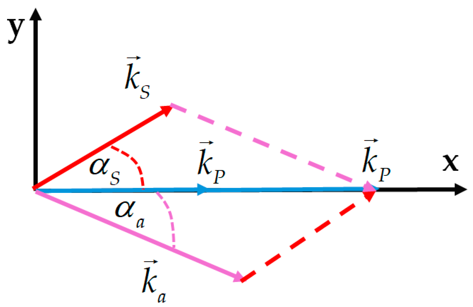
This appendix describes how the deviation angles of the Stokes and anti-Stokes components that form the Raman diffraction ring structure were estimated. Figure A1 shows the geometry of the beams forming the ring structure. The pump beam direction was chosen as the x-axis. The Stokes signal forms an angle with respect to this direction, whereas the anti-Stokes component forms an angle . Equation (1) written for the x- and y-components yields
From these equations, we obtain the equation for determination of as
Equation (A8) can be solved using the graphical method. We plot the left and right expressions of Equation (A8) as functions of . The solution is obtained at the intersection of the lines defined by these expressions.
Figure A1.
Schematic of the Stokes (red arrow), anti-Stokes (purple arrow), and pump wave (blue arrows) vectors that form the ring-shaped structure.
References
- Flors, C.; Griesbeck, A.G.; Vassilikogiannakis, G. Singlet Oxygen: Chemistry, Applications and Challenges Ahead. ChemPhotoChem 2018, 2, 510–511. [Google Scholar] [CrossRef] [Scilit]
- Curieles Andrés, C.M.; Pérez de la Lastra, J.M.; Juan, C.A.; Plou, F.J.; Pérez-Lebeña, E. Reactivity and Applications of Singlet Oxygen Molecule. In Reactive Oxygen Species—Advances and Development; Ahmad, R., Ed.; IntechOpen: London, UK, 2024. [Google Scholar] [CrossRef] [Scilit]
- Wang, Y.; Lin, Y.; He, S.; Wu, S.; Yang, C. Singlet Oxygen: Properties, Generation, Detection, and Environmental Applications. J. Hazard. Mater. 2024, 5, 132538. [Google Scholar] [CrossRef] [Scilit] [PubMed]
- Nidheesh, P.V.; Boczkaj, G.; Ganiyu, S.O.; Oladipo, A.A.; Fedorov, K.; Xiao, R.; Dionysiou, D.D. Generation, Properties, and Applications of Singlet Oxygen for Wastewater Treatment: A Review. Environ. Chem. Lett. 2025, 23, 195–240. [Google Scholar] [CrossRef] [Scilit]
- Nonell, S.; Flors, C. (Eds.) Singlet Oxygen: Applications in Biosciences and Nanosciences, Volume 2—Comprehensive Series in Photochemical & Photobiological Sciences, 1st ed.; Royal Society of Chemistry, Thomas Graham House: Cambridge, UK, 2016; Volume 14. [Google Scholar]
- Pibiri, I.; Buscemi, S.; Palumbo Piccionello, A.; Pace, A. Photochemically Produced Singlet Oxygen: Applications and Perspectives. ChemPhotoChem 2018, 2, 535–547. [Google Scholar] [CrossRef] [Scilit]
- Michelin, C.; Hoffmann, N. Photosensitization and Photocatalysis—Perspectives in Organic Chemistry. ACS Catal. 2018, 8, 12046–12055. [Google Scholar] [CrossRef] [Scilit]
- Frank Kino, F.; Medeiros Silva, G.T. The Photophysics of Photosensitization: A Brief Overview. J. Photochem. Photobiol. 2021, 7, 100042. [Google Scholar] [CrossRef] [Scilit]
- Olaizola, A.M.; Kuis, R.; Johnson, A.; Kingsley, D. Stimulated Raman Generation of Aqueous Singlet Oxygen without Photosensitizers. J. Photochem. Photobiol. B Biol. 2022, 235, 112562. [Google Scholar] [CrossRef] [Scilit] [PubMed]
- Marcano Olaizola, A.; Zerrad, A.; Jenneto, F.; Kingsley, D. Confirming the Stimulated Raman Origin of Singlet-Oxygen Photogeneration. J. Raman Spectrosc. 2024, 55, 58–64. [Google Scholar] [CrossRef] [Scilit]
- Marcano Olaizola, A. Near-Infrared Phosphorescence of Raman Photogenerated Singlet Oxygen. Photochem 2025, 5, 7. [Google Scholar] [CrossRef] [Scilit]
- Marcano Olaizola, A. Measuring the Efficiency of using Raman Photoexcitation to Generate Singlet Oxygen in Distilled Water. Photochem 2025, 5, 24. [Google Scholar] [CrossRef] [Scilit]
- Arbatskaya, A.N. Investigation of the Angular Distribution of Stimulated Raman Scattering of Light. In Stimulated Raman Scattering; Basov, N.G., Ed.; The Lebedev Physics Institute Series, Proceedings (Trudy) of the P.N. Lebedev Physics Institute; Springer: New York, NY, USA, 1982; Volume 99, pp. 1–36. [Google Scholar]
- Herzberg, G. Photography of the Infra-Red Solar Spectrum to Wave-length 12,900 A. Nature 1934, 133, 759. [Google Scholar] [CrossRef] [Scilit]
- Herzberg, L.; Herzberg, G. Fine Structure of the Atmospheric Oxygen Bands. Astrophys. J. 1947, 105, 353–359. [Google Scholar] [CrossRef] [Scilit]
- Ellis, J.W.; Kneser, H.O. Combination Relations in the Absorption Spectrum of Liquid Oxygen. Z. Phys. 1933, 86, 583–591. [Google Scholar]
- Krupenie, P.H. The Spectrum of Molecular Oxygen. J. Phys. Chem. Ref. Data 1972, 1, 423–534. [Google Scholar] [CrossRef] [Scilit]
- Meckler, A. Electronic Energy Levels of Molecular Oxygen. J. Chem. Phys. 1953, 21, 1750–1762. [Google Scholar] [CrossRef] [Scilit]
- Bachilo, S.M.; Nichiporovich, I.N.; Losev, A.P. Registration of Absorption of Oxygen in Solutions. J. Appl. Spektrosk. 1998, 65, 811–816. [Google Scholar] [CrossRef] [Scilit]
- Weldon, D.; Ogilby, P.R. Time-Resolved Absorption Spectrum of Single Oxygen in Solution. J. Am. Chem. Soc. 1998, 120, 12978–12979. [Google Scholar] [CrossRef] [Scilit]
- Krasnovsky, A.A., Jr.; Kozlov, A.S.; Roumbal, Y.V. Photochemical Investigation of the IR Absorption Bands of Molecular Oxygen in Organic and Aqueous Environment. Photochem. Photobiol. Sci. 2012, 11, 988–997. [Google Scholar] [CrossRef] [Scilit] [PubMed]
- Hellwarth, R.W. Theory of Stimulated Raman Scattering. Phys. Rev. 1963, 130, 1850–1852. [Google Scholar] [CrossRef] [Scilit]
- Garmire, E.; Panderese, F.; Townes, C.H. Coherently Driven Molecular Vibrations and Light Modulation. Phys. Rev. Lett. 1963, 11, 160–162. [Google Scholar] [CrossRef] [Scilit]
- Bloembergen, N. Nonlinear Optics, 4th ed.; World Scientific: Singapore, 1996; pp. 102–120. [Google Scholar]
- Boyd, R.W. Nonlinear Optics, 3rd ed.; Academic Press: Amsterdam, The Netherlands, 2008; pp. 473–509. [Google Scholar]
- Hill, K.O.; Kawasaki, B.S.; Johnson, D.C. Low-Threshold CW Raman Laser. Appl. Phys. Lett. 1976, 29, 181–183. [Google Scholar] [CrossRef] [Scilit]
- Kean, P.N.; Sinclair, B.D.; Smith, K.; Sibbett, W.; Rowe, C.J.; Reid, D.C.J. Experimental Evaluation of a Fibre Raman Oscillator Having Fibre Grating Reflectors. J. Mod. Opt. 1988, 35, 397–406. [Google Scholar] [CrossRef] [Scilit]
- Li, J.; Zhang, M. Physics and Applications of Raman Distributed Optical Fiber Sensing. Light Sci. Appl. 2022, 11, 128–157. [Google Scholar] [CrossRef] [Scilit] [PubMed]
- Tobita, R.; Kageyama, L.; Saito, A.; Tahara, S.; Kajimoto, S.; Nakabayashi, T. Highly Sensitive Raman Measurements of Protein Aqueous Solutions using Liquid–liquid Phase Separation. Chem. Commun. 2024, 60, 8732–8735. [Google Scholar] [CrossRef] [Scilit] [PubMed]
- Available online: https://refractiveindex.info/?shelf=3d&book=liquids&page=water (accessed on 18 July 2026).
- Kingsley, D.H.; Kuis, R.; Perez, R.; Basaldua, I.; Burkins, P.; Marcano Olaizola, A.; Johnson, A. Oxygen-Dependent Laser Inactivation of Murine Norovirus using Visible Light Lasers. Virol. J. 2018, 15, 117–124. [Google Scholar] [CrossRef] [Scilit] [PubMed]

Disclaimer/Publisher’s Note: The statements, opinions and data contained in all publications are solely those of the individual author(s) and contributor(s) and not of MDPI and/or the editor(s). MDPI and/or the editor(s) disclaim responsibility for any injury to people or property resulting from any ideas, methods, instructions or products referred to in the content. |
© 2026 by the authors. Licensee MDPI, Basel, Switzerland. This article is an open access article distributed under the terms and conditions of the Creative Commons Attribution (CC BY) license.