


Abstract
Bioreceptive building envelopes offer a potential pathway for integrating biological colonization into architectural surfaces. This article proposes a geometric design framework for bioreceptive façade components in which the surface itself is shaped to increase the exposed area available to the environment, and asks which admissible regular Euclidean tessellation maximizes that area. Triangular, square, and hexagonal tessellations are compared under a common circumscribed radius R and a common absolute indentation depth , counting only the inclined faces generated by the indentation. A closed-form expression is derived for the exposed-surface density , where is the apothem of the regular cell, and the triangular tessellation is shown to maximize it uniquely for every ; when the three configurations coincide. Because each inclined face has constant slope magnitude , the area Jacobian is constant, so clipping the indented surface with any measurable footprint of finite positive area gives exactly, with no boundary-error term. For the representative case , the hexagonal density is times the triangular one, equivalent to a triangular advantage specific to that ratio. An independently constructed CAD model reproduces the closed-form panel areas at both reference footprints to within and preserves the same ordering. Exposed area is a geometric descriptor of the available surface–environment interface and a candidate design parameter, not evidence of colonization, water behavior, or durability; no material, fabrication, or biological validation is claimed.
1. Introduction
1.1. Architectural Motivation: Toward Substrate-Free Bioreceptive Façade Components
Sustainability has become a defining concern in contemporary architectural design, particularly in relation to building envelopes, façade performance, material efficiency, and the integration of living systems into the built environment. Green façades, living walls, and vegetated architectural surfaces are widely explored as strategies for improving environmental quality, moderating microclimates, and increasing the ecological value of buildings. Nevertheless, many existing systems rely on additional substrates, containers, multilayer assemblies, irrigation membranes, or supporting frames. The present study does not compute whether omitting such layers changes mass, material volume, or total load; the comparison among the three tessellations is limited to exposed surface area.
An alternative design direction is to investigate whether the architectural component itself can contribute directly to biological receptivity. Instead of adding a separate growing medium as the primary support, this study investigates whether the exposed area of a mineral component can be increased through geometric configuration. This approach does not replace the need for material compatibility, water management, or biological validation, but it treats the façade element as a candidate biological support whose geometry determines the exposed surface area available for subsequent experimental evaluation.
Bioreceptivity—the capacity of a material surface to support biological colonization [1]—provides the conceptual basis for this approach. Across diverse systems, from microbial biofilms on engineered surfaces [2,3] to vegetation establishment on architectural substrates [4,5], the available contact surface area has been reported as one of several factors associated with organism attachment, nutrient exchange, and moisture interaction. Bioreceptivity is nevertheless a multivariable material and biological property, and reviews of bioreceptive concrete emphasize that it cannot be reduced to any single descriptor [6]. Previous studies have shown that material properties such as pH, porosity, roughness, water availability, and surface texture influence the colonization of concrete and mineral substrates [4,5,7,8]. In parallel, experimental work on microbial and biological surfaces indicates that substrate geometry and available contact area affect attachment, population distribution, and colonization dynamics [2,3].
These findings suggest that geometric design may contribute to the early-stage development of bioreceptive building components, provided that the geometric variables are made explicit and comparable. Exposed area can be treated as a first-order design parameter in this setting. A larger exposed area does not by itself establish colonization, root development, or ecological performance; it is treated here only as a geometric measure of the nominal surface–environment interface.
Research gap, question, and hypothesis. Within the literature reviewed here, four strands can be distinguished. Bioreceptivity is studied as a multivariable material and biological property governed by porosity, pH, mineralogy, roughness, and moisture [1,6]. Bioreceptive architectural design proposes the envelope itself as a biological host rather than a carrier for added planting [9,10]. Computational and performance-based methods generate and evaluate façade configurations, including tessellated envelopes and robotically fabricated bioreceptive surfaces [11,12,13]. Nature-based solutions and green-envelope research treat vegetated roofs and façades as technically differentiated building systems, with construction requirements and reported performance related to thermal and energy behavior, storm water management, and life-cycle constraints [14,15,16,17]. These references provide building-envelope context only; the corresponding performance outcomes are not evaluated for the indented surface studied here. What these strands leave open is a closed comparison of the admissible regular tessellations themselves under an explicitly stated normalization. This article therefore asks which regular Euclidean tessellation maximizes the exposed-surface density of a cellwise indented panel, and tests one purely geometric hypothesis: under a common circumscribed radius and a common absolute indentation depth, the triangular tessellation yields the highest density. This is not a biological hypothesis. The contribution is bounded accordingly to the class , the exposed-surface-per-projected-area functional, the stated normalizations, and an exact analytical solution.
We therefore formulate a geometric design framework for regular tessellated façade components that isolates the contribution of surface geometry while keeping material conditions, circumscribed radius, and indentation depth fixed. The analysis serves as a design tool for comparing surface configurations under explicitly stated geometric normalizations.
We model the panel as a tessellated planar domain with cell-wise concave indentations. Biological colonization tests, material ageing, and long-term façade performance lie outside the scope of this article. The resulting exposed-surface functional is comparable across tessellations under a common circumscribed radius and a common absolute indentation depth, and it admits a closed-form reduction, which makes it usable for early-stage screening of tessellated façade components before prototyping.
1.2. Geometric Design Problem and Analytical Formulation
We represent an idealized panel or façade component through its planar projection. Let be a bounded measurable domain representing the projected footprint of the specimen, and denote its area by .
Regularity assumption. We assume only that is Lebesgue measurable with , which is sufficient for the clipping construction and for the area identity of Corollary 1. Panel footprints of practical interest, such as squares and rectangles, satisfy this trivially.
We tessellate with a regular tiling consisting of congruent regular polygons, each inscribed in a circle of common radius R; we write for a single representative tile of . We restrict the admissible class to regular monohedral Euclidean tessellations. A classical classification theorem in discrete geometry [18] establishes that the only regular polygons that tile the Euclidean plane by congruent copies are the equilateral triangle, the square, and the regular hexagon. Consequently, the admissible set is exactly . In Schläfli notation, the admissible regular tessellations are (triangles), (squares), and (hexagons).
Allowing irregular (non-regular or non-monohedral) tessellations would define a different problem class: heterogeneous cells would not share a single apothem, and additional constraints would be required to keep the maximization well posed and comparable. We therefore treat as the natural admissible set under uniform cell geometry.
On each cell of the tessellation, we apply an identical concave indentation of depth , mapping the planar domain to a piecewise planar surface . Its total exposed three-dimensional surface area (i.e., the sum of the lateral faces of the inverted pyramidal cells; no horizontal base faces are counted) is denoted by .
- Notation. Throughout the paper, depends on the tessellation type n, the circumscribed radius R, the indentation depth , and the domain . When no ambiguity arises and R, , and are fixed, we write for brevity.
The optimization problem is:
1.3. Why the Optimal Tessellation Depends on the Design-Performance Functional
The Honeycomb Theorem (Hales [19]) establishes that among all partitions of the Euclidean plane into regions of equal area, the regular hexagonal tiling minimizes total perimeter. The optimality of the hexagon therefore depends on the specific choice of functional (planar interface length) and on the admissible class (all equal-area partitions).
In the present work, the admissible class is restricted to regular monohedral Euclidean tessellations, and the objective functional is fundamentally different: we maximize exposed three-dimensional surface area generated by a cell-wise indentation operator. For a regular n-gon inscribed in a circle of radius R, the apothem is , and the exposed-surface density per unit projected area is
Since is strictly decreasing in , and the apothems satisfy , the ordering of optimality reverses relative to the perimeter-minimization setting. This does not contradict the Honeycomb Theorem; it illustrates that geometric optimality is functional-dependent. In architectural terms, the best tessellation is not universal: it depends on whether the design-performance criterion is material minimization, planar packing, surface exposure, hydraulic retention, or another environmental objective.
- On the choice of normalization. Fixing R is a direct geometric normalization: it controls the maximum radial extent of each cell, from its center to its vertices, and corresponds exactly to the construction used here, in which every polygon is inscribed in a circle of the same radius. The depth is an absolute perpendicular displacement of the center, common to the three tessellations. The ordering is not exclusive to the common-circumradius normalization. As shown in Table 1, it is also preserved under a common side length or a common cell area, provided that the three tessellations are compared at the same absolute indentation depth. The result nevertheless remains conditional on the normalization: if a common aspect ratio is imposed instead, the three densities coincide.Table 1. Apothem under three geometric normalizations. In all three cases ; therefore, with a common absolute indentation depth , the ordering is unchanged.
The operative condition is that the depth is fixed in absolute terms. Were the aspect ratio held common instead, would take the same value for every n and no ordering would exist. That is a different normalization problem; the present result is conditional on a common R and a common absolute .
1.4. Contributions and Organization
This article provides:
- A design-performance formulation for bioreceptive façade components based on exposed surface area, with an analytical derivation of for .
- A geometric proof that triangular tessellation maximizes exposed-surface density under a common circumscribed radius and a common absolute indentation depth.
- An exact clipping result showing that the same ordering holds for any measurable panel footprint, with no boundary-error term.
- A design-oriented interpretation linking the mathematical result to the design of mineral façade components with increased exposed surface.
The remainder of the paper defines the geometric model, derives closed-form expressions for the exposed surface area, proves the optimality ordering among the three regular Euclidean tessellations, and discusses implications for bioreceptive surface design.
1.5. Notation Conventions
Throughout this article, we adopt the following conventions.
- : bounded measurable domain representing the projected panel footprint, with area
- : number of sides of the regular polygon (triangle, square, hexagon)
- : the infinite regular tessellation of type n
- : a single representative tile of , that is, one regular n-gon inscribed in the circle of radius R
- : circumscribed radius, common to the three tessellations
- : absolute indentation depth, common to the three tessellations
- : side length of the regular n-gon
- : apothem of the regular n-gon
- : slant height of an inclined face
- : planar projected area of one representative tile
- : exposed area of one indented tile, inclined faces only
- : exposed-surface density per unit projected area
- : exposed area of the indented tessellated surface clipped by the footprint ; equivalently
- , the reduced function governing the optimization problem
The density is dimensionless and admits the reading of an amplification factor , since it is the ratio between generated surface and consumed footprint. In the derivations, statements, and conclusions below we use the single symbol .
Note that is a representative tile, not a fundamental domain of the translation lattice. A translation does not change the orientation of a triangle, so a primitive translational cell of the triangular tiling contains two triangles of opposite orientation. The density does not require a lattice fundamental domain, since it is computed on a single tile.
When no ambiguity arises, the explicit dependence on n, R, , and is omitted for notational convenience.
2. Geometric Model of the Indented Bioreceptive Panel
2.1. Reference Cell Geometry
2.1.1. Definition of the Inscribed Polygon in a Circle
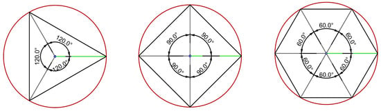
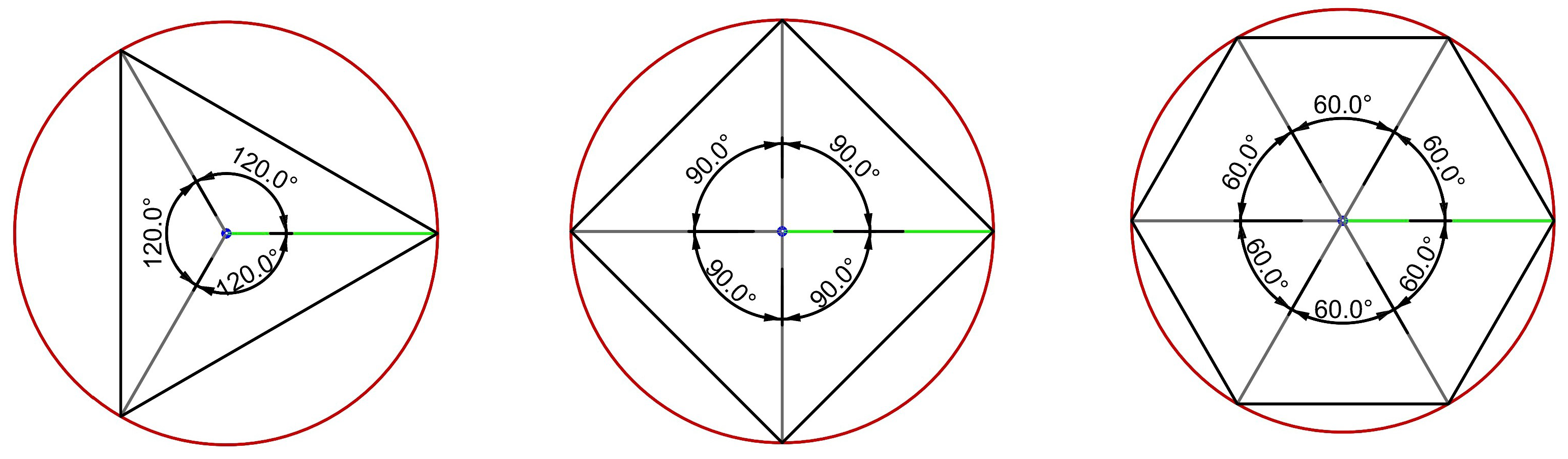
Figure 1 illustrates the admissible regular polygons inscribed in a circle of fixed radius R, from which the apothem is defined.
Figure 1.
Regular polygons () inscribed in a circle of fixed radius R. The apothem and interior angles are illustrated.
Definition 1.
A regular polygon (equal sides and equal angles) is inscribed in a circle if all its vertices lie on that circle. If the polygon has n sides and a circumscribed circle with radius R, then the vertices can be located in polar coordinates as
2.1.2. The Indentation Transformation
Definition 2.
Given a polygon with n vertices in the plane, the centroid, G, of this polygon is defined as follows:
Definition 3.
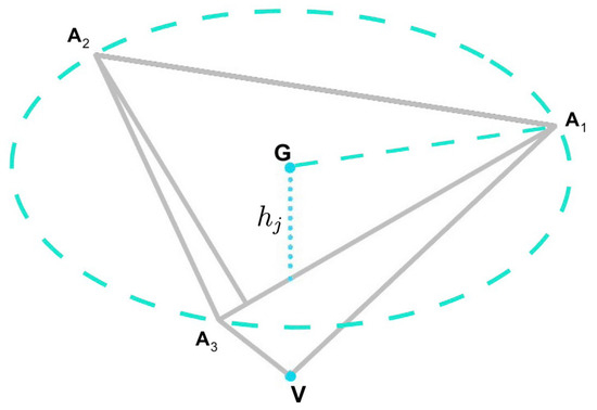
Given a polygon of n vertices, we define the indented polygon as an n-gonal pyramid . The base is the polygon in the plane , the apex is the point located directly below the centroid G, and the lateral faces are the planar triangles for (indices modulo n). The depth of the indentation is the perpendicular distance from the apex V to the centroid G of the polygon.
Figure 2 illustrates the indentation of a regular triangle inscribed in a circle.
Figure 2.
Indentation of a regular triangular cell: the centroid G is projected vertically to the apex V at depth , generating lateral triangular faces.
2.2. Tessellated Panel Construction
2.2.1. The Tessellation Process of the Plane
The admissible tessellation class consists of exactly three regular polygons that tile the plane: equilateral triangle, square, and hexagon. The angles meeting at each tiling vertex sum to .
To tessellate a planar domain in , we consider the base plane
Tessellation Generation Algorithm:
- Selection of the representative polygon. Let n be the number of sides and define the central angle:
- Edge length calculation. Given circumscribed radius R, the side length is
- Definition of the center set. For , cell centroids form a Bravais lattice generated by two translation vectors :Remark. One may take as the standard primitive translation vectors of the corresponding square/hexagonal lattice; their explicit form is not required for the area derivations below.For the triangular tiling (), congruent equilateral triangles occur in two opposite orientations, so the centroid set is the union of two translated sublattices. Let a be the triangle side length and defineThen the centroids are
- Construction of each cell. For we place translated copies of the single representative cell:For we use two congruent representative cells and (opposite orientations) and placewhich yields the regular tiling without gaps.
The mathematical theory of tessellations, lattices, and sphere packings is extensively developed in the literature [20,21]. Variational and measure-theoretic approaches to surface functionals are treated in geometric measure theory [22].
2.2.2. The Indentation Process of the Tessellated Panel
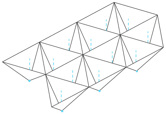
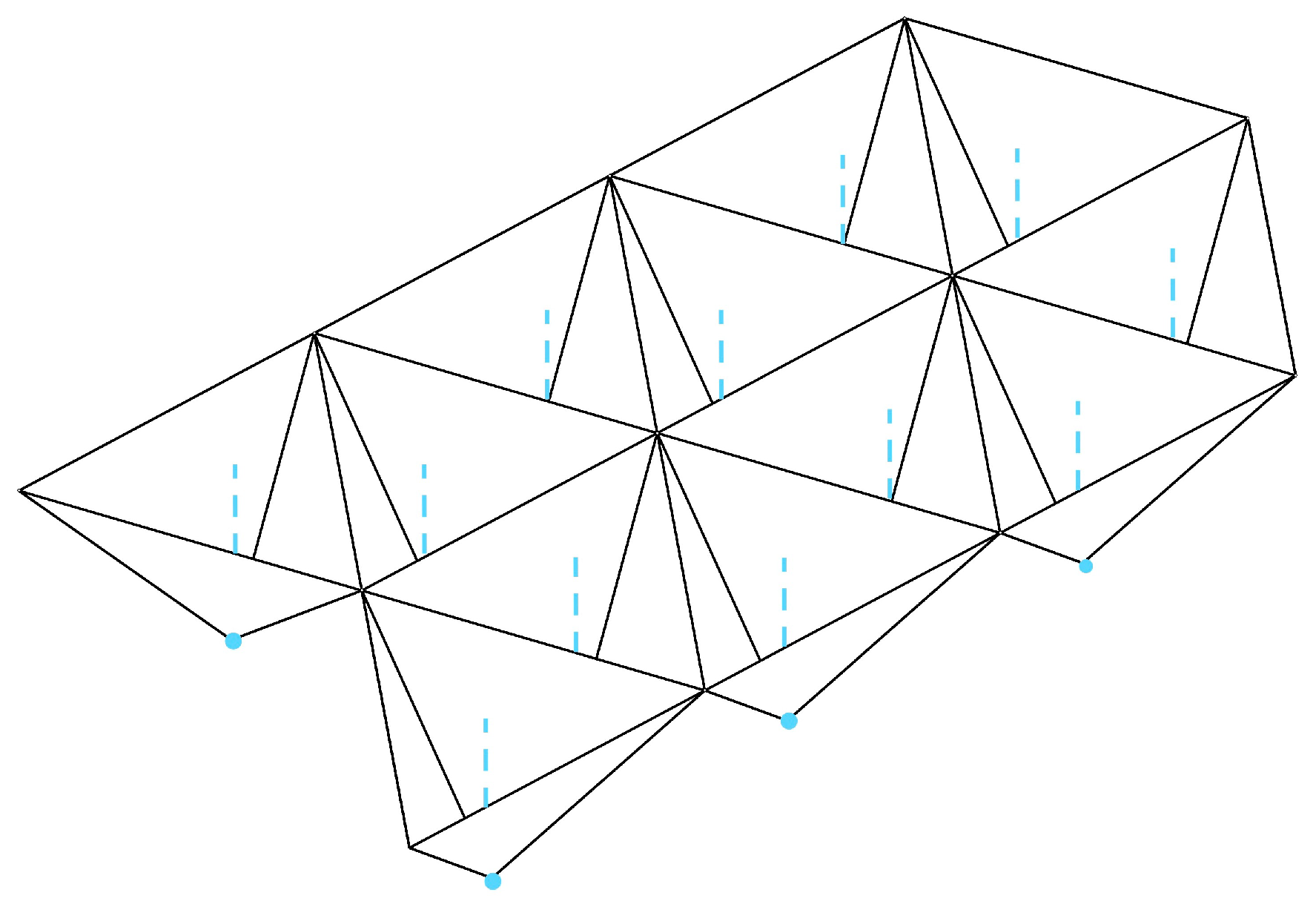
From a planar tessellation, we apply the indentation transformation to each cell. This process converts each polygon into a concave pyramid by projecting the centroid vertically downward by depth (Figure 3). In an architectural interpretation, the resulting surface is a tessellated mineral panel whose lateral faces constitute the exposed surface–environment interface.
Figure 3.
Tessellated triangular panel after applying the cell-wise indentation operator. Each cell forms an inverted pyramid contributing lateral exposed area.
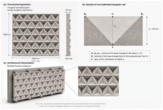
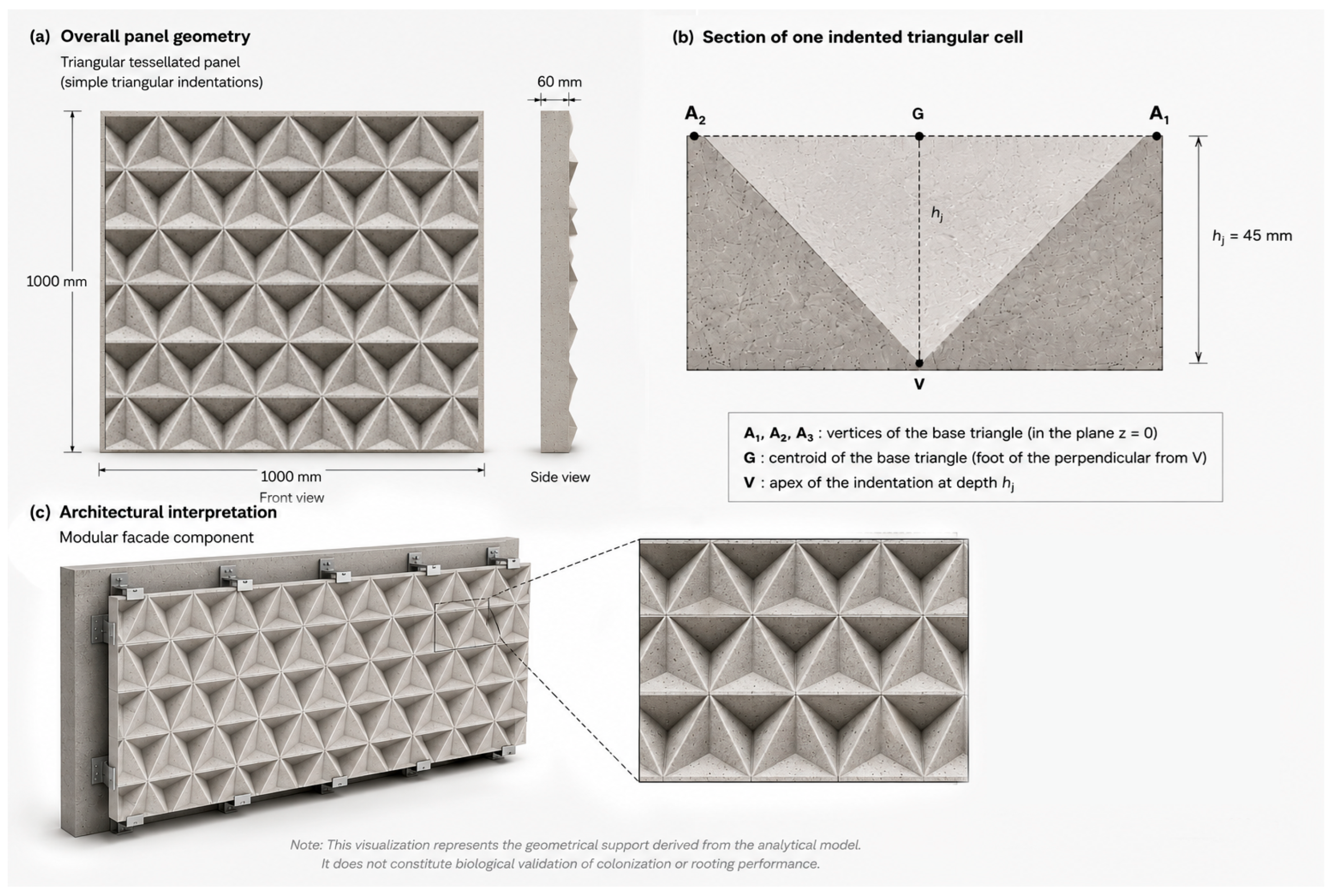
Figure 4 translates the same geometric principle into a conceptual architectural visualization, including the overall panel geometry, a sectional reading of one triangular indentation, and a possible modular façade interpretation.
Figure 4.
Conceptual visualization of a possible architectural application of the triangular tessellated bioreceptive panel derived from the exposed-surface maximization criterion. (a) Overall panel geometry showing a regular array of simple triangular concave indentations; (b) sectional interpretation of one indented triangular cell, indicating the base vertices, centroid G, indentation apex V, and depth ; (c) architectural interpretation of the system as a modular mineral façade component. The figure is conceptual: it does not represent a fabricated component, and it constitutes neither constructive, nor structural, nor biological validation.
The tessellated domain is transformed to a piecewise-linear surface with increased total area.
3. Surface Amplification Analysis
3.1. Cell-Level Geometry
3.1.1. Surface Area Formulations
For each indented polygon type, we report (i) the planar projected area of the cell, , and (ii) the exposed three-dimensional surface area generated by indentation, defined as the sum of the lateral triangular faces only (no horizontal base faces are counted).
Definition 4
(exposed cell area). Let be the inverted n-gonal pyramid obtained by indenting the regular n-gon , with apex . We define the exposed surface area of a single cell as
Equivalently, if is the area of one lateral face, then
where is the side length and is the apothem of the base polygon.
- Counting convention. The exposed-surface functional counts only the lateral triangular faces. Base faces are excluded. This is a geometric counting convention; no biological accessibility, attachment, exchange, or performance is inferred from it.
For triangle, square, and hexagon, respectively, the planar projected cell areas are , , and , while the exposed lateral areas are , , and .
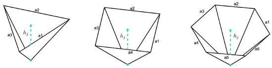
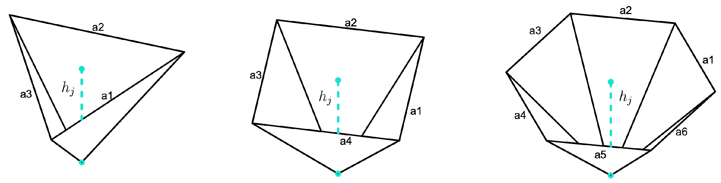
The three admissible indented cell geometries are shown in Figure 5.
Figure 5.
Indented triangular, square, and hexagonal cells under identical , illustrating differences in perimeter and lateral surface generation.
3.1.2. Cell-Level Area Is Not a Sufficient Design Criterion
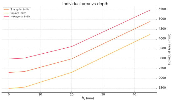
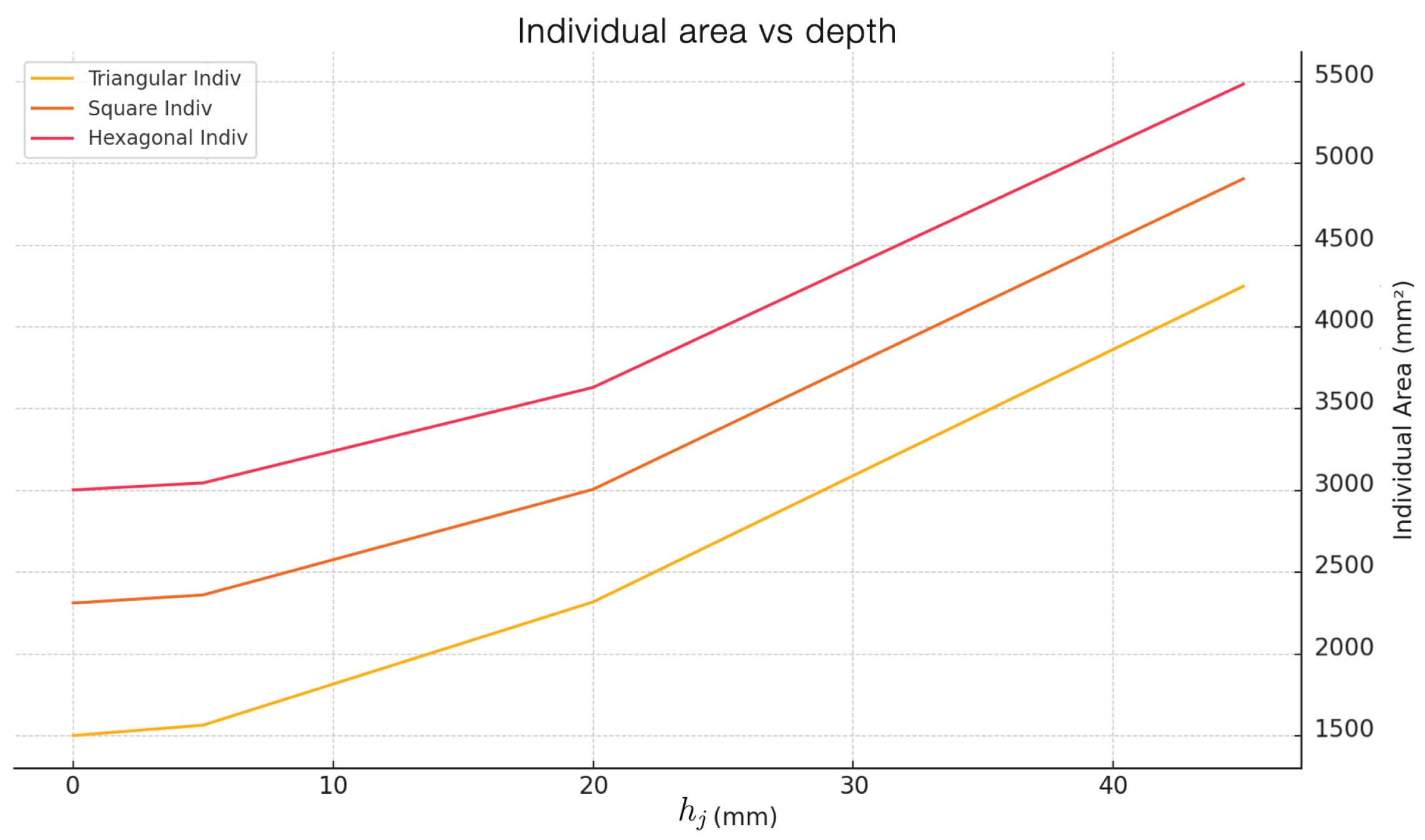
Figure 6 shows the relationship between individual surface area and indentation depth for the three configurations, with constant circumscribed radius R.
Figure 6.
Individual cell exposed area versus indentation depth for common R, showing hexagonal dominance at the single-cell level. This is not the panel-scale criterion.
For fixed R and , the hexagonal cell always exhibits the largest individual surface area, followed by square, then triangular. This ordering reflects the larger perimeter of hexagons relative to triangles inscribed in the same circle. However, individual cell area does not determine panel-scale optimality when cells must pack within a bounded architectural domain. This distinction is central for design: a geometry that appears more efficient as a single unit may become less efficient once the number of cells per unit area is taken into account.
3.2. Panel-Scale Optimization
The total exposed area for a tessellated domain depends on both individual cell geometry and the number of cells per unit area.
3.2.1. Individual Cell Geometry
For a regular n-sided polygon with circumscribed radius R and indentation depth , the side length, apothem, base area, slant height, face area, and exposed cell area are
When no ambiguity arises, we abbreviate and .
3.2.2. Periodic Domain Formulation
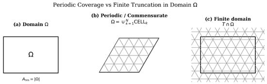
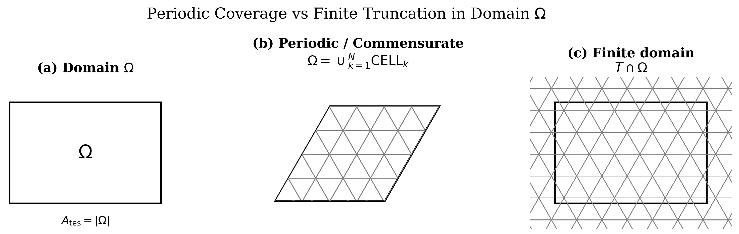
Setting. The indented surface is generated from the infinite tessellation of by applying the indentation operator to every tile. The exposed-surface density is defined on a single representative tile and requires neither a lattice fundamental domain nor any commensurability between the panel footprint and the tile area. The finite panel is then obtained by clipping the indented surface with the vertical projection of the footprint (Figure 7), so that cells crossing the boundary are partially cut. Only the inclined faces retained inside are counted; flat bases, the rear face of the panel, vertical closing faces, and perimeter walls are excluded throughout.
Figure 7.
Construction of a finite panel. (a) The planar footprint of area . (b) A tile-aligned footprint, whose boundary follows cell edges. (c) General case: the indented tessellation is clipped by , so that boundary cells are partially cut. By Corollary 1 the exposed area equals in all of these cases.
The resulting total exposed three-dimensional surface area is
an identity established in Corollary 1 without any commensurability hypothesis.
3.2.3. Surface-Amplification Criterion
In the indented configuration, each tessellation cell forms an inverted n-gonal pyramid. The exposed surface of each cell consists solely of its lateral triangular faces; no horizontal interior base face is present.
Substituting and into the expression for gives
Thus,
and the geometric amplification factor is
This expression is the design-performance criterion used in the present study. It converts the comparison of tessellated architectural surfaces into a direct relation among cell apothem, indentation depth, and total exposed area.
3.2.4. Panel-Scale Reference Values
The closed-form expression derived above allows direct evaluation of the exposed surface area at the scale of an architectural panel. For the representative parameters used in the analytical and computational evaluation,
the apothems of the three admissible cells are
Substitution into the amplification factor
gives the theoretical panel-scale values reported in Table 2. These values follow from the exact identity of Corollary 1 and therefore hold for the square panel footprints considered here, irrespective of the phase or orientation of the tessellation.
Table 2.
Panel-scale exposed surface area for the representative design case (, ). Values are obtained from the closed-form expression , which by Corollary 1 is exact for any measurable clipped footprint.
Under the exact clipped-surface model, the triangular tessellation provides the largest exposed surface area at both reference panel scales. At the representative depth-to-radius ratio , it provides approximately more exposed surface than the hexagonal configuration:
3.2.5. Normalized Density Ratio as a Function of
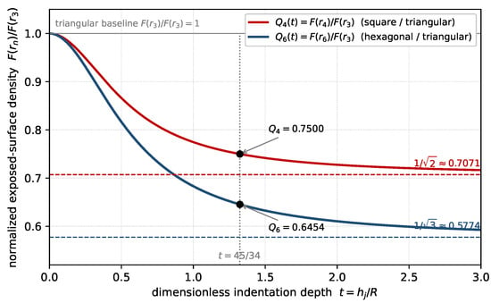
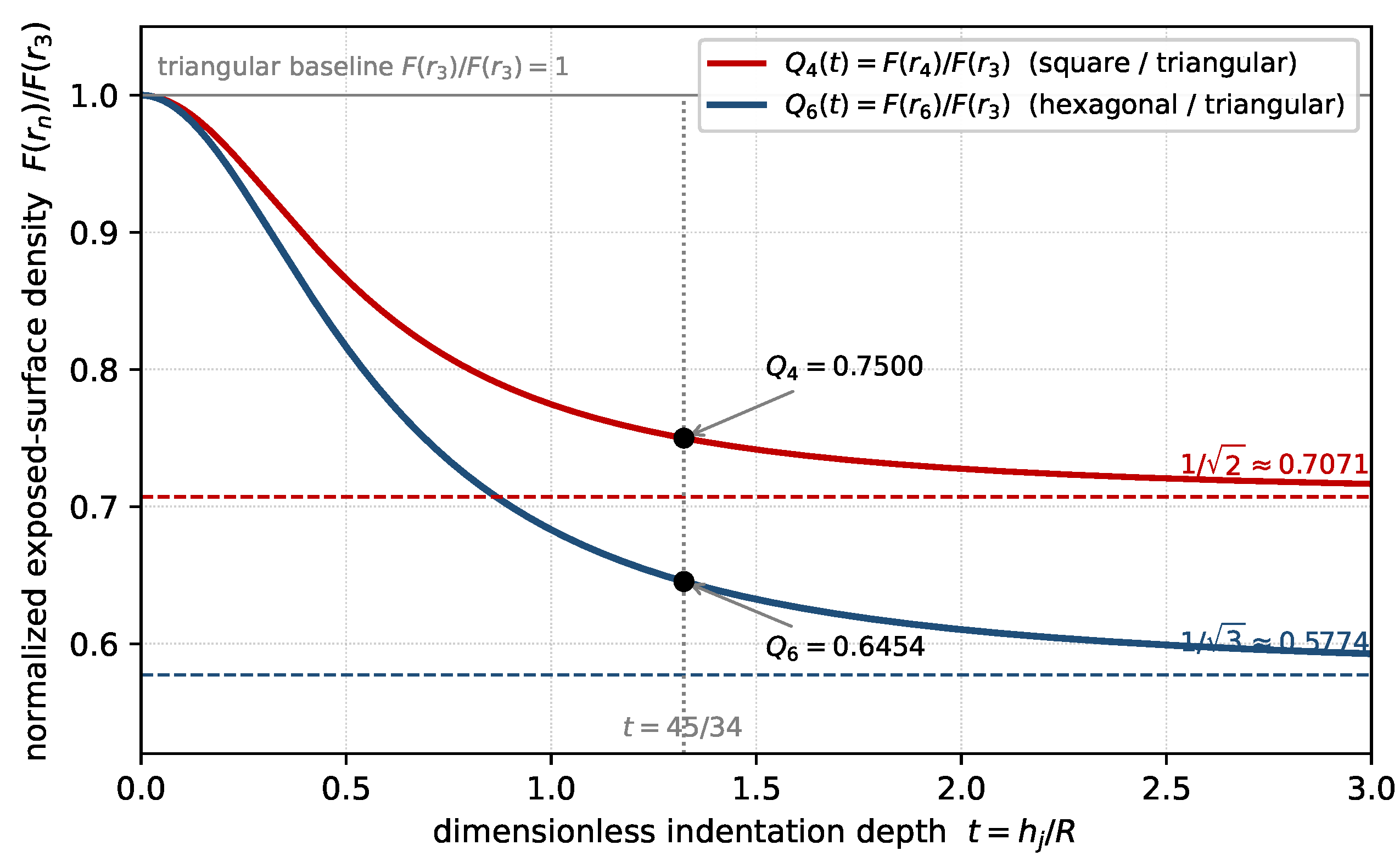
The percentage above is the value at one depth-to-radius ratio and should not be read as a general figure. Let and normalize the density of each tessellation by the triangular one. Since , and ,
Both ratios equal unity in the flat limit, , and decrease monotonically toward the finite asymptotes
For the representative case one obtains and . The latter is the same result as the percentage quoted above, since . Figure 8 plots both ratios; the interval shown is a range for mathematical visualization and is not a validated fabrication range.
Figure 8.
Normalized exposed-surface density of the square and hexagonal tessellations, relative to the triangular one, as a function of the dimensionless indentation depth , under a common circumscribed radius and a common absolute depth. Both ratios start at unity when and decrease toward the asymptotes and . The marked ordinates are the values at the representative case . The range shown serves mathematical visualization only and does not represent a validated fabrication range.
3.2.6. Linear Scaling and Domain Invariance
From the surface-amplification criterion, for fixed n, R, and , the total exposed surface scales linearly with the domain area :
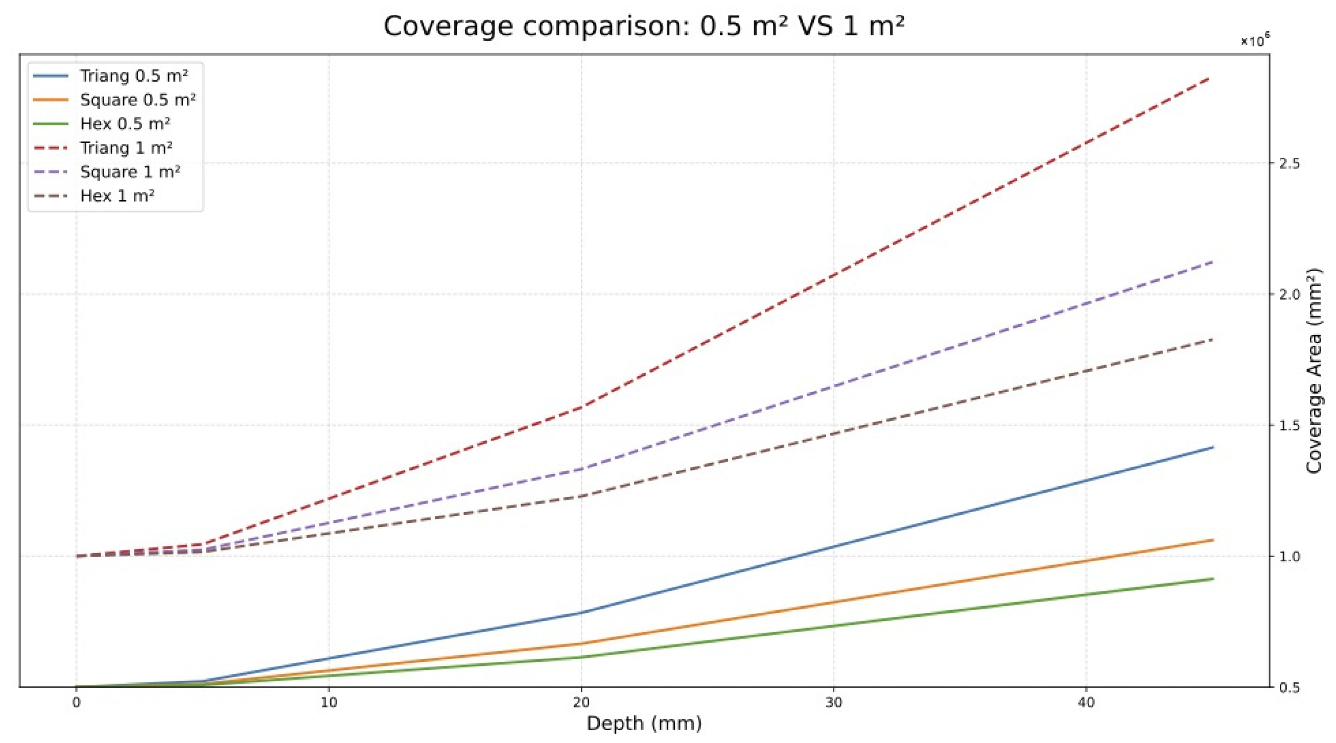
By Corollary 1 the constant of proportionality is for clipped panels as well as for tile-aligned ones, so the total exposed area scales exactly linearly with in both cases. Doubling the footprint area exactly doubles .
The panel-scale curves presented below illustrate this linear scaling property and the ranking
is invariant under domain rescaling.
3.2.7. Comparative Analysis at Panel Scale
We work with reference domains of and , the reference panel areas used in this study.
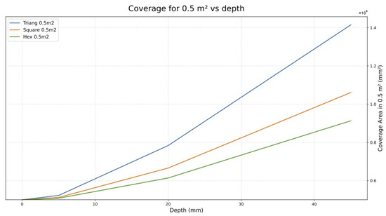
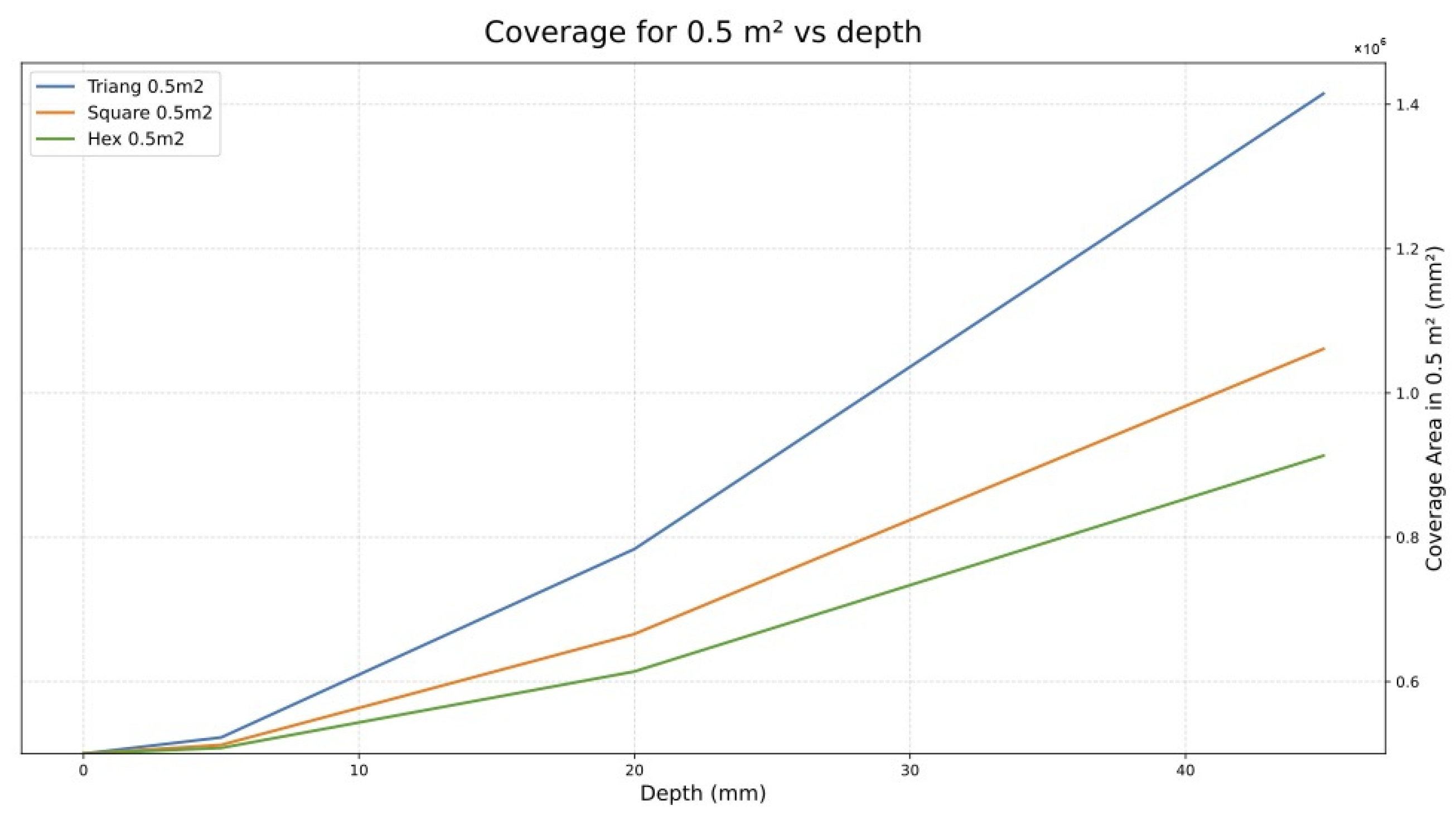
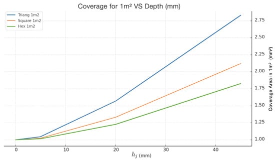
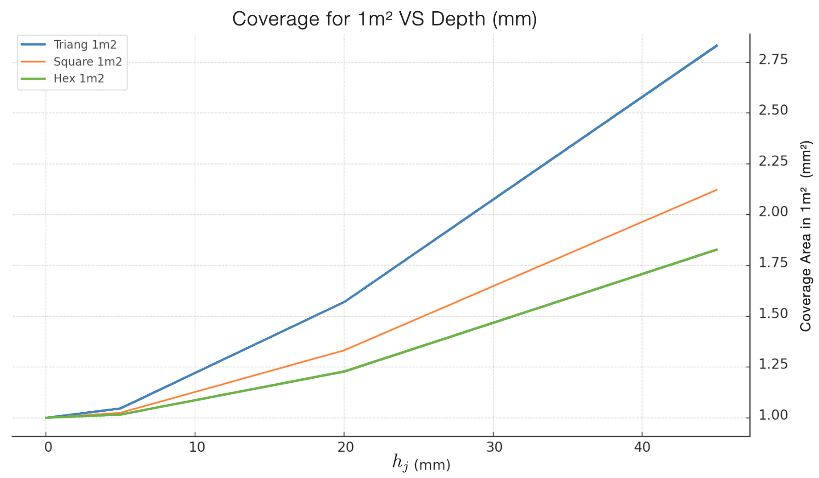
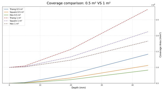
- Panel-scale curves. Figure 9, Figure 10 and Figure 11 report the panel-scale exposed area as a function of indentation depth for square footprints of and , as analytical evaluations of .Figure 9. Total panel exposed area versus indentation depth for triangular, square, and hexagonal tessellations on a clipped architectural panel footprint. Compare with Figure 6, which reports the exposed area of a single cell.Figure 10. Total panel exposed area versus indentation depth for triangular, square, and hexagonal tessellations on a clipped architectural panel footprint.Figure 11. Total exposed surface area as a function of indentation depth for triangular, square, and hexagonal tessellations on architectural panel domains of and .
Result: Unlike the individual-cell behavior (Figure 6), at panel scale the triangular configuration achieves the highest total exposed area, followed by square, then hexagonal.
Explanation. The two figures report different quantities, so there is no contradiction. Figure 6 plots the exposed area of a single cell, and a hexagonal cell inscribed in a circle of radius R has the largest perimeter and hence the largest single-cell area. Figure 9, Figure 10 and Figure 11 plot the exposed area per unit of panel footprint, governed by the density , equivalently by the face slope . The triangular cell has the smallest apothem, so its faces are steepest at a common absolute depth; the reversal follows, and holds for every .
3.2.8. Design Criterion: Triangular Tessellation Maximizes Exposed-Surface Density
Theorem 1
(Triangular optimality of the exposed-surface density). Let and be common to the admissible tessellations, and for let
computed on a representative tile and counting inclined faces only. Then:
- 1.
- if , then and , so no ordering exists;
- 2.
- if , then .
Proof.
Write for , so that .
If , then for every , which gives (i).
Let . A direct computation yields
so F is strictly decreasing on . Since
strict monotonicity gives , which is (ii). □
Corollary 1
(Exact exposed area of a clipped panel). Fix , and . Over each inclined face the indented surface is the graph of an affine function whose gradient has constant magnitude
so that the area Jacobian is constant almost everywhere:
Consequently, if the indented tessellated surface is clipped by the vertical projection of any measurable planar footprint Ω with , and only the retained inclined faces are counted, then
exactly. In particular, for the ordering holds for every such footprint, whatever the phase or orientation of the tessellation, and for the three areas equal .
Proof.
Each inclined face is a planar triangle joining an edge of a tile to the displaced center. On the interior of such a face is affine, and equals the rise over the horizontal run from edge to center, a value independent of the face and of the tile. Ridges and tile boundaries form a locally finite union of line segments, a set of planar Lebesgue measure zero, and so do not affect the integral. The area formula for the graph of a Lipschitz function gives the identity, and the constancy of the integrand allows it to be factored out of the integral. □
- Scope of the identity. Corollary 1 accounts for the inclined faces only. Flat bases, the rear face of the panel, vertical closing faces at the panel perimeter, and any other surface lie outside the functional and are not included in . Within that scope the panel result is exact rather than asymptotic: there is no boundary-error term and no large-panel hypothesis.
3.2.9. Degenerate Baseline at and Strict Ordering for
In the flat case () there is no indentation: and , so a panel of footprint has exposed area for the three tessellations alike. At cell level, with , but that difference is exactly compensated at panel scale, because the density normalizes the exposed area of a cell by the footprint the cell consumes. For , and Theorem 1 gives . The flat configuration is therefore a degenerate baseline, while indentation induces a strict ordering.
- Non-uniform indentation depth. For a cell or region carrying a local depth h, the local density is
3.3. Established Analytical Results
Under the construction defined above, holds exactly for every footprint with , so that for all under a common R and a common absolute , counting inclined faces only. For the three values coincide.
3.4. Geometric Construction and Independent CAD Evaluation
The closed-form expression is exact and does not require numerical approximation. A computer-aided design (CAD) model was nevertheless constructed and measured independently, providing an independent numerical check using a separately constructed CAD geometry. It is not a physical simulation, it does not represent a fabricated object, and it is not the proof of the theorem, which is established analytically above.
3.4.1. Construction Procedure
For each a single regular n-gon was inscribed in a circle of radius R, so that its vertices lie on the circle and R is the distance from the center of the polygon to any of its vertices. The center G was identified; in a regular polygon the centroid, circumcenter, and incenter coincide. The polygon was divided into n triangular faces by joining G to the vertices, each face having a polygon edge as its base and G as its apex. The outer vertices were held fixed in the plane and G was displaced perpendicularly by the absolute distance , generating an inverted pyramidal indentation formed exclusively by n planar triangular faces. Cells were tessellated sharing their upper edges, without gaps.
For the regular triangular tessellation was used: equilateral triangles appear in two opposite orientations and six meet at each vertex. Each triangle is an individual cell inscribed in its own circle of radius , with its own geometric center and its own indentation point. In the CAD model a visual grouping of six triangles forming a hexagon was used only as an auxiliary repetition module for building the tessellation. It is neither an indented hexagonal cell nor a single indentation shared by six triangles: the point that descends is the center of each individual triangle, not the common vertex where six triangles meet. The triangles tessellate the plane without gaps, and the macro-hexagonal grouping changes neither the definition of the triangular cell nor its exposed area.
3.4.2. CAD Environment
The models were built in Rhinoceros 8, version 8.33.26188.13002 (7 July 2026). Document units were millimeters and the absolute tolerance was . All faces were represented as NURBS surfaces. Areas were obtained with the Area command, and the reported quantity is the sum of the areas of the retained green NURBS surfaces after trimming.
3.4.3. Finite Panel Construction
For each tessellation a grid extending beyond the panel outline was generated first. A square outline enclosing a projected area of or was then applied, and the surfaces were cut cleanly at that boundary with the Split command. Only the portions of the green faces lying inside the outline were retained and measured. Cells intersected by the perimeter were not discarded as whole cells: their faces were trimmed at the modeled panel boundary.
3.4.4. Surface Area Evaluation
Only the parts of the inclined faces remaining inside the square footprint enter the area computation, matching the scope of the analytical functional; by Corollary 1 the expected value is times the panel area.
3.4.5. Cell-Level Reference Values
For representative parameter values ( and varying ), the closed-form exposed lateral area per cell is reported in Table 3. These values are not the panel-scale optimization criterion; they are included to clarify the difference between individual-cell behavior and exposed area per unit of panel footprint. At the cell level the hexagon has the largest exposed area. At panel scale, as shown in Table 2, the density reverses the ordering and leads to triangular optimality.
Table 3.
Exposed lateral surface area per cell (lateral faces only, in ) for representative indentation depths. These values describe individual cells, not total panel-scale exposed area.
The same check was performed on the CAD model at cell level. For and the Area command returns for the triangular cell, for the square cell and for the hexagonal cell, each with a numerical area uncertainty of reported by the Rhino Area command. These reproduce the closed-form values of the last row of Table 3 to within .
3.5. Independent CAD Verification at Panel Scale
Table 4 compares the closed-form panel areas with the areas measured on the CAD model, for , and the two reference footprints.
Table 4.
Closed-form and independently measured CAD exposed areas for and , counting only the retained inclined faces, where and . Analytical values follow from with , and .
The CAD models reproduce the analytical ordering, triangle > square > hexagon, at both panel sizes, and the results at and are approximately proportional to the projected area within the reported CAD discrepancies. The largest discrepancy is that of the triangular panel at , approximately ; the remaining five are below .
The source of the small CAD discrepancies was not isolated and is therefore not assigned to a specific modeling or numerical operation. They are reported transparently and do not affect the triangle–square–hexagon ordering. They should not be interpreted as a mathematical boundary-error term: under the exact clipped-domain definition, remains the analytical identity, whereas the tabulated residuals belong to the numerical CAD evaluation.
4. Discussion
4.1. Architectural Interpretation of the Geometric Result
The triangular tessellation maximizes exposed surface area at panel scale under a common circumscribed radius and a common absolute indentation depth, which follows from the monotonicity of the density with respect to the apothem. The result provides a direct criterion for selecting the topology of a tessellated bioreceptive panel. Although the hexagonal cell has the largest exposed area as a single indented unit, the triangular tessellation prevails at panel scale, so the conclusion is a panel-scale one and not a property of isolated geometry.
4.2. Implications for Substrate-Free Green Façade Systems
Some conventional vegetated envelopes incorporate a distinct growing medium, modular containers, felt layers, or multilayer irrigation assemblies; the investigated concept seeks to use the mineral surface itself as a potential biological support, and whether it performs that function requires experimental validation. This study does not compute whether omitting those additional layers changes mass, material volume, or total load.
Within this paradigm, exposed surface area becomes a design variable, and increasing the area of the inclined faces enlarges the interface between the component and its environment. The triangular configuration is a geometric optimum for the stated functional; whether it is preferable overall depends on criteria not modeled here. Exposed surface area and material efficiency are distinct objectives, and only the first is quantified. The framework isolates the geometric contribution so that subsequent experimental work can test whether the increased exposed area has any biological consequence.
4.3. What the Exposed-Surface Functional Does Not Describe
The quantity computed here is exposed surface area. It is not a model of water retention, accumulation, drainage, drying, moisture persistence, freeze–thaw behavior, durability, or colonization, and none of these can be inferred from it. A concave indentation may drain rapidly or retain water depending on orientation, depth, surface finish, and exposure, and retained water raises a legitimate freeze–thaw concern. Establishing any of these behaviors would require dedicated testing, which this work does not undertake.
4.4. Fabrication Considerations
The geometry analyzed here is an ideal zero-thickness surface and does not establish fabricability. For the representative triangular case, and , corresponding to a face inclination of approximately relative to the projected plane. The ideal tessellation also fixes the length of the shared edge network per unit projected area, , which is largest for the triangular case. Both quantities are geometric descriptors only: neither determines ridge width, rear thickness, or material volume.
No physical prototype has been fabricated in the present study. Material selection, panel thickness, ridge and apex geometry, manufacturing process, structural performance, and fabrication tolerances remain to be defined and tested in a subsequent experimental phase. Accordingly, no fabrication-feasibility or material-volume comparison is claimed.
4.5. Relation to Bioreceptive Surface Design
The exposed-surface density is a geometric descriptor of the available surface–environment interface and a candidate design parameter; it is not evidence of colonization. The literature cited here supports the general relevance of contact area and of material factors such as pH, porosity, roughness, and moisture [2,3,4,5,6,7,8], but does not establish that the inclined faces of a triangular indentation support more colonization than a planar surface or another tessellation. That remains a hypothesis requiring biological validation.
Mustafa et al. [4] developed design guidelines for bio-receptive concrete panels through laboratory fabrication and greenhouse experiments, manipulating surface geometry and rhythmic patterns. Lewandowski et al. [5] identified high pH as a major constraint and demonstrated that compost additions compensate for adverse material characteristics. The present framework contributes a rigorous comparison of tessellation topologies under an explicit area-maximization objective.
4.6. Tessellation Theory and Contemporary Computational Design
Recent advances in tessellation theory have found applications in bio-inspired design [23,24,25]. Those works address irregular and adaptive patterns; the present focus on regular tessellations is complementary, since for periodic patterns with uniform cell geometry the choice among the three tilings has quantifiable consequences for exposed area.
Within computational architectural design, tessellated envelopes have been used as a parametric control strategy for façade components evaluated against environmental performance criteria [12], and performance-based methods couple generative geometry with simulation to compare façade configurations [11]. Bioreceptive surfaces have more recently entered this workflow, both as monitored micro-environments for bryophyte propagation [10] and as robotically fabricated clay façades whose toolpaths are engineered for water behavior [13], while nature-based solutions research treats vegetated envelopes as coupled multi-criteria problems [14]. The present formulation is narrower and complementary: a closed-form comparison of the admissible regular tessellations under a stated normalization.
4.7. From Analytical Geometry to Future Prototype Development
Although the analytical model is scale-independent, the panel-scale evaluation is carried out on a centimetric analytical and computational design case. The parameter pair and does not correspond to a fabricated prototype, a validated manufacturing configuration, or a species-specific biological requirement, and no general lower bound on cell size is claimed. Within these limits, the triangular tessellation is the candidate base topology for subsequent experimental development, and the result links an abstract geometric functional to a concrete design decision: the selection of the tessellation family for a façade component.
4.8. Limitations and Extensions
The present analysis is subject to the following limitations.
- Uniform depth: the depth is assumed identical in every cell. The non-uniform case is treated above; tessellation-dependent depth perturbations would require a sensitivity analysis, which is not performed here.
- Planar domains: Euclidean geometry only; no extension to curved substrates.
- Regular monohedral tessellations: only the three admissible Euclidean types .
- Stated normalization: the ordering holds under a common circumscribed radius and a common absolute indentation depth. Under a common aspect ratio the three densities coincide and no ordering exists.
- Scope of the functional: only the inclined faces are counted. Flat bases, the rear face of the panel, vertical closing faces, and perimeter walls are excluded.
- Fabrication not evaluated: thickness, ridge width, apex geometry, tolerances, demolding, and structural integrity are not modeled.
- Hydraulics and durability not evaluated: water retention, drainage, drying, moisture persistence, freeze–thaw behavior, and long-term durability lie outside the model.
- CAD as verification, not validation: the CAD study checks the closed-form expressions numerically. It validates neither fabrication, nor material, nor structural or biological behavior.
- Biology not tested: no colonization, rooting, or aging experiment is reported. Exposed area is a geometric descriptor, not evidence of biological performance.
- Material properties outside the model: bioreceptivity depends on material factors such as porosity, pH, and chemistry [1,5,6,7]; the analysis isolates the geometric contribution under fixed material conditions.
- Scale selection not validated: the reference parameters (, ) define a centimetric analytical and computational design case. The closed-form expression applies across scales, but a suitable scale depends on the target species, the system, and the fabrication process, and is not validated here.
5. Conclusions
This article developed a geometric design framework for substrate-free or substrate-minimized bioreceptive architectural components, asking whether the surface of a façade element can be analytically configured to maximize the exposed surface area available for environmental interaction.
Within the admissible class of regular Euclidean tessellations, triangular, square, and hexagonal patterns were evaluated under a common circumscribed radius R and a common absolute indentation depth , counting inclined faces only. A closed-form expression was derived for the exposed-surface functional, showing that the total exposed area depends on the apothem of the regular cell through the amplification factor
Because this function is strictly decreasing in , and because the triangular tessellation has the smallest apothem among the three admissible regular tessellations, the triangular configuration uniquely maximizes exposed surface area for all . When there is no indentation, the three densities equal unity, and no ordering exists.
The result is exact for finite panels as well. Since each inclined face has constant slope magnitude , the area Jacobian is constant, and clipping the indented tessellation by any measurable footprint with yields an exposed area of exactly , whatever the phase or orientation of the tessellation, provided only the inclined faces are counted. An independently constructed CAD model reproduces these panel areas at both reference footprints, with a largest relative discrepancy of about and the same ordering.
The result demonstrates a functional inversion relative to classical perimeter-minimization theory. Whereas the hexagon is optimal for minimizing planar interface length in the Honeycomb Theorem (Hales [19]), the triangle becomes optimal when the design objective is to maximize three-dimensional exposed surface generated by concave indentation. This distinction is relevant for architectural design because it shows that the optimal tessellation depends on the geometric functional being prioritized.
By reframing classical tessellation theory [18] in terms of surface amplification, the present work establishes an analytical criterion for design problems involving exposed-surface maximization, directly computable from closed-form expressions and therefore usable for rapid screening under the stated normalization, without numerical meshing.
For the representative case , the normalized densities are and , the latter equivalent to a triangular advantage over the hexagonal configuration. These values are specific to this ratio, and the triangular configuration is the candidate geometric basis for subsequent prototyping. No material, mass, or fabrication comparison has been carried out, and the exposed-surface result is not evidence of colonization, water behavior, or durability.
- Future directions. Practical bioreceptive surface design involves objectives beyond exposed area, including water retention, structural stability, material durability, and biological compatibility [5]. Future work should couple the exposed-surface functional with these variables and move to prototype validation, using the triangular configuration as reference geometry.
Author Contributions
Conceptualization, M.J.L.G., P.V.-G. and N.M.S.; methodology, M.J.L.G., P.V.-G. and N.M.S.; software, M.J.L.G.; validation, M.J.L.G., L.H.P., P.V.-G. and N.M.S.; investigation, M.J.L.G., P.V.-G. and N.M.S.; data curation, M.J.L.G.; writing—original draft preparation, M.J.L.G.; writing—review and editing, M.J.L.G., L.H.P., P.V.-G. and N.M.S.; visualization, N.M.S.; supervision, M.J.L.G., P.V.-G. and N.M.S.; project administration, M.J.L.G. All authors have read and agreed to the published version of the manuscript.
Funding
This research received no external funding.
Institutional Review Board Statement
Not applicable.
Informed Consent Statement
Not applicable.
Data Availability Statement
Data supporting the reported results are available from the corresponding author upon reasonable request.
Conflicts of Interest
The authors declare no conflicts of interest.
References
- Manso, S.; De Muynck, W.; Segura, I.; Aguado, A.; Steppe, K.; Boon, N.; De Belie, N. Bioreceptivity evaluation of cementitious materials designed to stimulate biological growth. Sci. Total Environ. 2014, 481, 232–241. [Google Scholar] [CrossRef] [Scilit]
- Rodríguez, D.; Einarsson, B.; Carpio, A. Biofilm growth on rugose surfaces. Phys. Rev. E 2012, 86, 061914. [Google Scholar] [CrossRef] [Scilit] [PubMed]
- Postek, W.; Staśkiewicz, K.; Lilja, E.; Wacław, B. Substrate geometry affects population dynamics in a bacterial biofilm. Proc. Natl. Acad. Sci. USA 2024, 121, e2315361121. [Google Scholar] [CrossRef] [Scilit] [PubMed]
- Mustafa, K.F.; Prieto, A.; Ottelé, M. The role of geometry on a self-sustaining bio-receptive concrete panel for facade application. Sustainability 2021, 13, 7453. [Google Scholar] [CrossRef] [Scilit]
- Lewandowski, D.; Robain, H.; Clergeau, P.; Le Roy, R. Bioreceptivity of living walls: Interactions between building materials and substrates, and effect on plant growth. Urban For. Urban Green. 2023, 83, 127912. [Google Scholar] [CrossRef] [Scilit]
- Stohl, L.; Manninger, T.; von Werder, J.; Dehn, F.; Gorbushina, A.; Meng, B. Bioreceptivity of concrete: A review. J. Build. Eng. 2023, 76, 107201. [Google Scholar] [CrossRef] [Scilit]
- Rotondi, C.; Gironi, C.; Ciufo, D.; Diana, M.; Lucibello, S. Bioreceptive ceramic surfaces: Material experimentations for responsible research and design innovation in circular economy transition and “ecological augmentation”. Sustainability 2024, 16, 3208. [Google Scholar] [CrossRef] [Scilit]
- Hofbauer, W.K. Early colonisation of modern building surfaces. Plant Ecol. Divers. 2025, 18, 237–247. [Google Scholar] [CrossRef] [Scilit]
- Cruz, M.; Beckett, R. Bioreceptive design: A novel approach to biodigital materiality. Archit. Res. Q. 2016, 20, 51–64. [Google Scholar] [CrossRef] [Scilit]
- Lăcătuşu, A.; Cruz, M.; Parker, B.; Salmane, A. Biocentric Design: Mapping Optimal Environmental Variables for Moss Propagation on Urban Bioreceptive Surfaces. In Proceedings of the SIGraDi 2022: Critical Appropriations, Lima, Peru, 7–11 November 2022; pp. 1251–1262. [Google Scholar] [CrossRef] [Scilit] [PubMed]
- Gerber, D.J.; Pantazis, E.; Wang, A. A multi-agent approach for performance based architecture: Design exploring geometry, user, and environmental agencies in façades. Autom. Constr. 2017, 76, 45–58. [Google Scholar] [CrossRef] [Scilit]
- Hanafin, S.; Datta, S.; Rolfe, B.; Hobbs, M. Envelope Tesselation with Stochastic Rotation of 4-Fold Penttiles. In Proceedings of the Beyond Codes and Pixels: Proceedings of the 17th International Conference on Computer-Aided Architectural Design Research in Asia (CAADRIA 2012), Chennai, India, 25–28 April 2012; pp. 253–262. [Google Scholar] [CrossRef] [Scilit]
- Li, C.; Lange, C.J.; Wu, K. Magnifying the Micro-Scale: Thermographic-enabled Toolpath Engineering for Water Retention in Robotic Clay-3D-Printed Bioreceptive Façade. In Proceedings of the SIGraDi 2024, Barcelona, Spain, 13–15 November 2024; pp. 2337–2348. [Google Scholar] [CrossRef] [Scilit]
- Ascione, F.; De Masi, R.F.; Mastellone, M.; Ruggiero, S.; Vanoli, G.P. Green Walls, a Critical Review: Knowledge Gaps, Design Parameters, Thermal Performances and Multi-Criteria Design Approaches. Energies 2020, 13, 2296. [Google Scholar] [CrossRef] [Scilit]
- Pfoser, N. Green Facades; DETAIL Business Information GmbH: Munich, Germany, 2024. [Google Scholar] [CrossRef] [Scilit]
- El-Zoklah, M.H.S. Green Façades. MATTER Int. J. Sci. Technol. 2016, 2, 325–340. [Google Scholar] [CrossRef] [Scilit]
- Santos, T.D.d.O.; Pacheco, F.A.L.; Fernandes, L.F.S. A Systematic Analysis on the Efficiency and Sustainability of Green Facades and Roofs. Sci. Total Environ. 2024, 932, 173107. [Google Scholar] [CrossRef] [Scilit] [PubMed]
- Grünbaum, B.; Shephard, G.C. Tilings and Patterns; W. H. Freeman: New York, NY, USA, 1987. [Google Scholar]
- Hales, T.C. The Honeycomb Conjecture. Discret. Comput. Geom. 2001, 25, 1–22. [Google Scholar] [CrossRef] [Scilit]
- Conway, J.H.; Sloane, N.J.A. Sphere Packings, Lattices and Groups; Springer: New York, NY, USA, 1988. [Google Scholar]
- Fejes Tóth, L. Regular Figures; Pergamon Press: Oxford, UK, 1964. [Google Scholar]
- Morgan, F. Geometric Measure Theory: A Beginner’s Guide, 4th ed.; Academic Press: Burlington, MA, USA, 2009. [Google Scholar]
- Arvizu-Alonso, A.K.; Armendáriz-Mireles, E.N.; Calles-Arriaga, C.A.; Rocha-Rangel, E. Control of the Properties of the Voronoi Tessellation Technique and Biomimetic Patterns: A Review. Designs 2024, 8, 93. [Google Scholar] [CrossRef] [Scilit]
- Li, Z.; Chu, S.; Wu, Z.; Xiao, J. A novel bio-inspired design method for porous structures: Variable-periodic Voronoi tessellation. Mater. Des. 2024, 243, 113055. [Google Scholar] [CrossRef] [Scilit]
- Solera Jimenez, M.; Cortesão, J.; Lenzholzer, S.; van den Dobbelsteen, A. Plant pixel: An optimized bio-inspired living wall system. Dev. Built Environ. 2024, 18, 100438. [Google Scholar] [CrossRef] [Scilit]

Disclaimer/Publisher’s Note: The statements, opinions and data contained in all publications are solely those of the individual author(s) and contributor(s) and not of MDPI and/or the editor(s). MDPI and/or the editor(s) disclaim responsibility for any injury to people or property resulting from any ideas, methods, instructions or products referred to in the content. |
© 2026 by the authors. Licensee MDPI, Basel, Switzerland. This article is an open access article distributed under the terms and conditions of the Creative Commons Attribution (CC BY) license.