


Abstract
The results of the development and practical application of a comprehensive system for studying gear cutting processes are presented. The processes are traditional hobbing, modern power skiving, and radial-circular methods. Carrying out these processes is based on the gear teeth continuous generating method using complex kinematics. This complicates the analysis, description and modeling of the processes. The developed system provides for a logical sequence of step-by-step modeling and simulation of interrelated processes and phenomena accompanying gear processing. Reproducing volumetric chips and calculating their parameters provides the basis for determining deformation and contact processes, cutting forces, elastic deformations, machining accuracy and energy costs per operation. After establishing the operation to overcome friction and heat flows, the degree of heating and the temperature of the working surfaces are calculated to predict tool wear and its service life. Based on the parametric non-uniformity of the considered processes, the intensity of oscillations and vibrations of gear cutting machines is predicted, and their impact on the quality of gear surfaces and the accuracy of gears is determined. These approaches enable the study of such processes at the level of individual teeth and blades during cutting. They also allow gear cutting technology and cutting tools to be optimized according to the most important criteria and performance assessments.
1. Introduction: Literature Review
Gear transmissions will remain integral components of modern machines and mechanisms. They are used in drives, reducers, gearboxes and speed boxes. These provide changes in speed, torque and direction of the executive links. Gears are used in all industries, including defense, automotive, aerospace, robotics, and various types of industrial equipment. According to [1], the Global Gear Technology Market was valued at $121.63 billion in 2024 and is projected to reach $192.41 billion by 2031, growing at an average annual rate of 5.90%.
A certain change in this trend occurred in the automotive industry after the invention and industrial use of electric drives. However, recent studies have shown the need to supplement electric drives with mechanical transmissions and return to traditional approaches, reversing this trend. The combination of electric drives with mechanical 2–8-stage gearboxes increases the transmission ratio and reduces the output shaft speed. As a result, this has made it possible to increase the torque and power of the drive, as well as extend the service life of electric motors. In such contexts, research in gear and transmission technology that is aimed at optimization through comprehensive and systematic modeling of the multifaceted processes and phenomena that accompany gear wheel cutting is highly relevant to modern mechanical engineering.
Due to the significance of the subject under study, numerous publications are available today presenting the results of scientific research on various aspects of it, such as cutting force calculations, temperature and tool structure [2,3,4,5,6,7,8,9,10,11,12,13].
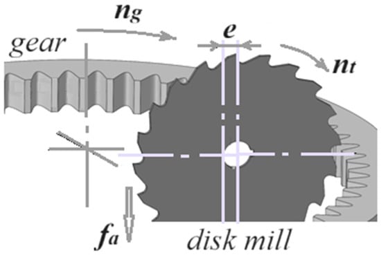
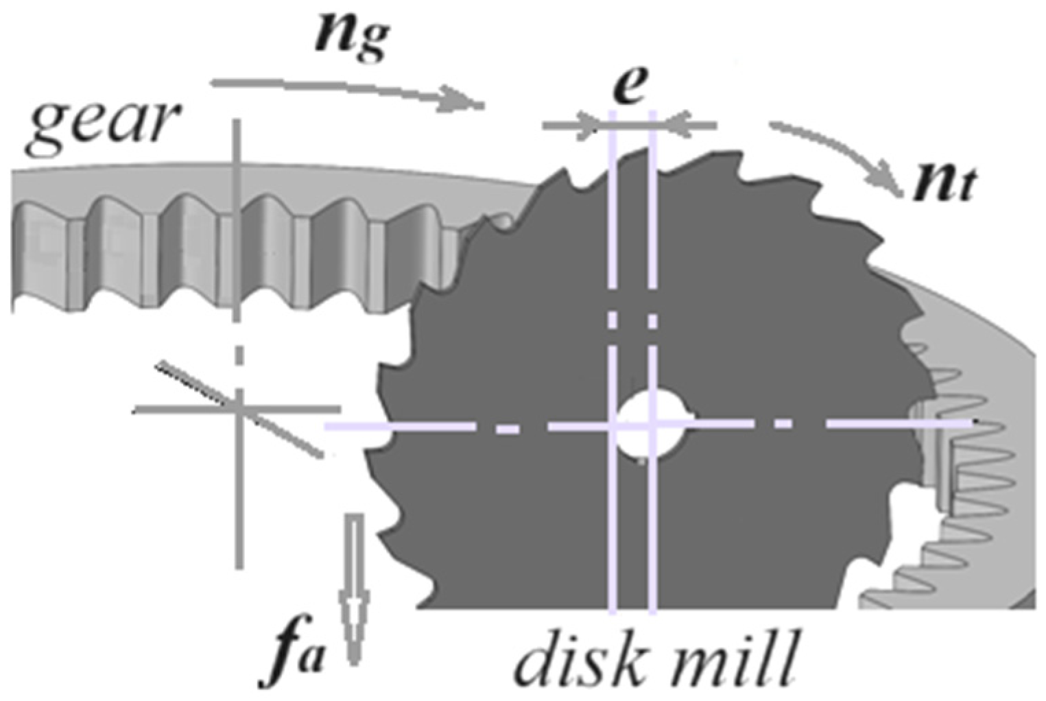
At the same time, certain shortcomings can be noted in many publications, typical errors of which can be illustrated by the example of approaches to assessing cutting force. The complexity of the processes under study makes modeling them difficult. Consequently, the analysis is often based on simplified approaches and assumptions, reducing the value of the results obtained. Thus, when determining the morphology of chips cut by a skiver in the Power Skiving method, the following diagram is often used (Figure 1) [6,8,14,15], where the cutting motion does not correspond to the actual kinematics. Power Skiving reproduces the movement of two gears, one of which is a tool, positioned at an angle. This angle determines the position of the cutting vector plane (20° for straight-toothed wheels) relative to the end face of the workpiece. It is important to note that this is not the same as what is commonly thought, that the plane is perpendicular to the end face.
Figure 1.
Kinematic diagram of gear cutting using the radial-circular method, nt is tool rotation frequency, ng is workpiece rotation frequency, fa is axial feed of the tool, and e is eccentricity of the disc mill.
When describing cutting force, in many cases, the shape and dimensions of the actual transition surface between the tooth movement trajectory and the tooth marks that formed this gap earlier, in the previous angular and linear positions of the tool, are not taken into account. A similar mistake is made when replacing the cutting of a gear with a hob, which is a multi-tooth and multi-blade tool, with a single-tooth flying cutter [13,16,17,18,19], because in this case, too, the kinematics of continuous gear generation is not reproduced.
Many studies present reliable and verified results from cutting force experiments [2,20,21,22,23,24]. However, these results only apply to the conditions in which the experiment was conducted and cannot be extrapolated to other initial data. Simplified theoretical models are often supplemented with experimental data entered into formulas as a set of correction coefficients, thereby narrowing the scope of application of such results.
Many studies of force rely solely on the thickness of the cuts on the hob cutting edges [7,20,25,26,27]. However, unlike the cross-sectional area of the cuts, the thickness of the cut layers is a partial parameter of the chips and does not allow adequate reproduction of the cutting force. This reduces the value of such studies.
The use of a specific cutting force [7] is common in cutting force calculations. This value is usually assumed to be constant for a given material. In reality, however, this parameter depends on the deformation allowance and the actual dimensions of the cuts, both of which change with each tooth and also during the cutting motion of the same tooth. Therefore, calculating the load based on the specific cutting force will not produce adequate results.
Recent publications indicate a growing interest in face gears, which are now being used in aircraft gearboxes, speed reducers, and special angular gearboxes [28,29]. The traditional gear cutting methods of hobbing [29] and power skiving [28] are adapted for their manufacture. In particular, [28] studies the effect on gear surfaces of the kinematic angles generated by the skiving cutter as a result of the crossing of axes, whilst [29] investigates the effect of chips on the torque during hobbing. The use of the Power Skiving method for finishing gear ends after tooth cutting and for chamfering is described in [30]. Huang, K. and Fu, C. [31] explore the influence of gear cutting machine dynamics on the surface topography of spiral bevel gears, taking into account the spectral structure of the surface. Refs. [32,33] considered the modeling of thermal processes and their impact on process accuracy: thermal errors and the temperature of the worktable of a gear grinding machine are described in [32], whilst [33] develops a mechanism for thermal transient processes. The influence of operating modes and cooling conditions on surface quality during machining is described in [34]. Given the importance of gear quality in modern mechanical engineering, a number of authors have explored the issue of accuracy. For instance, Ref. [35] describes the machined tooth surface as a set of sinusoidal irregularities with different frequencies, determining its accuracy on the basis of an analysis of sound vibration spectra and their intensity. Article [36] describes the modeling of kinematic errors during the cutting of gear rims using approaches based on probabilistic models, whilst [37] investigates the effect of abrasive flow on the quality of helical bevel gears.
Article [38] is concerned with the problems of machining toothed surfaces by shaving; it examines the influence of cutting force, cutting speed and the angle of intersection of the axes on the error in tooth direction.
The issue of improving the environmental sustainability of production is becoming increasingly relevant today. It is addressed in [39], which examines the challenges of minimizing coolant usage and energy consumption during gear grinding using a multi-objective optimization model.
Similar shortcomings are also observed in the analysis and description of other processes and phenomena during gear cutting. Based on this situation, the aim of this article is to develop the principles of comprehensive and systematic modeling of the main gear cutting processes carried out under conditions of continuous gear surfaces rolling and generating, taking into account the peculiarities of their kinematics in order to optimize these processes and select rational parameters for their operation in production conditions.
2. Research Results
The development of gear wheel production today is moving towards the creation of new methods and the improvement of traditional technologies, the introduction of new materials, automation and technologies based on artificial intelligence. Modern transmissions must meet a range of requirements, including reducing noise levels and failures, increasing durability, and reducing weight and size. At the same time, they must address the challenges of increasing productivity and efficiency, reducing operating costs, and saving energy resources. In a competitive market, this presents a significant challenge to gear transmission manufacturers.
Tooth-cutting operations are central to the gear manufacturing cycle. These operations are the most labor-intensive, and the costs incurred at this stage largely determine the overall cost of gears and transmissions. The main methods of gear machining are hobbing, power skiving, shaping with a modular chisel and the radial-circular method (RCM, Figure 1), developed at Lviv Polytechnic National University. The radial-circular method uses a thin disc cutter on a gear cutting machine to form the gear surfaces by giving the cutter a cyclical movement in the radial direction. This movement can be created either by a radial displacement of the cutter corresponding to the wheel module or by a servo-driven mechanism providing periodic reciprocating motion to replace the cutter’s eccentricity. The use of serial equipment and the simplest cutting tools for the manufacture of external and internal wheels of various types and forms of mashing makes it as efficient and flexible as possible.
The cost of gear transmissions can account for up to 40% of the total cost of manufacturing machines due to the complexity and labor intensity of gear cutting processes. Therefore, there is an urgent need to improve technology and reduce the costs of gear manufacturing of the required quality in the necessary quantities. Solving this problem reduces to choosing the optimal cutting condition for machining operations, designing rational cutting tools with the most efficient structure and geometric parameters, and establishing the optimal structure, content, and sequence of technological operations and steps.
Compliance with all requirements for the organization of production is a controversial process that involves compromises and mutual restrictions on certain parameters of operations. Increasing the cutting speed to boost productivity can lead to higher costs due to the reduced lifespan of expensive cutting tools. Increasing the cutting depth and feed rate can reduce machine time but causes increased elastic deformation, as well as oscillations and chatter. These factors negatively affect machining quality and equipment service life. Replacing high-speed steels with hard and super-hard materials that can operate under more intensive working conditions increases the cost of cutting tools. Increasing the number of active teeth and blades to improve material removal productivity during cutting leads to an increase in the total forces acting on the tool and machine, which also negatively affects the condition of the machines and increases power energy costs.
In practice, various methods and approaches are employed to address this issue. These include:
- -
- Experimental methods based on field studies in production or laboratory conditions, which often use mathematical statistical methods;
- -
- Theoretical probability methods that combine theoretical calculations with the forecasting of production activity results based on probability theory;
- -
- Analytical methods based on scientific developments in cutting theory, heat engineering, thermophysics, materials science and machine dynamics.
In recent years, such research has been automated and optimized using serial and original application packages and computer design systems. Combining these software products with the latest scientific advances provides an optimal solution to this type of problem, enabling the optimization of technological solutions at all stages of gear manufacturing. However, well-known specialized programs and systems often remain the secret of their developers, and are unavailable for widespread practical use, or serve as commercial products on the market for design services and scientific research. In this regard, this paper proposes an approach that presents a methodology for solving a sequence of problems in order to optimize cutting methods and gear manufacturing technology.
The aforementioned processes are united by the fact that they occur during the continuous generation of toothed surfaces, representing the most complex cutting process. Their kinematics are based on four working movements.
The main cutting motion is the rotary motion of the tool. The auxiliary motions are the axial feed of the tool and the circular feed of the workpiece. The auxiliary cutting motion is provided by the tool’s design and is specific to each method. The constructive additional movements that occur when the tool rotates are the following:
- -
- In hobbing: axial displacement of the hob blades and teeth located on the screw surface;
- -
- In the power skiving method, the tool is displaced in the direction of the workpiece axis due to the intersection of the tool and wheel axes;
- -
- In the radial-circular method, the tool undergoes cyclic displacement in the radial direction relative to the workpiece axis due to the eccentricity of the disc cutter.
These constructive movements ensure the process of continuous cutting and tooth generation and distinguish them from simple methods such as turning, drilling, milling, broaching, etc. The multi-coordinate kinematic diagrams of these processes make their theoretical study difficult. In order to optimize these processes, it is important to develop a unified methodology for their analysis, research, mathematical description and modeling based on systematic principles. These principles require tasks and stages to be considered in relation to each other and based on previous results, and for a unified system to consist of smaller subsystems, in order to comply with the requirements of comprehensiveness and structure.
In accordance with this approach, simulating gear cutting processes involves the following steps:
- development of a geometric spatial model of the cut layers and determination of their parameters—cross-sectional area, thickness and width of cuts, contact length and cutting path at the level of the single teeth and blades;
- studying the intensity of deformation processes during chip formation;
- analyzing the cutting force and its components as a function of the parameters of the cuts, the intensity of chip shear stress and the properties of the workpiece material;
- study of the features of a particular tooth processing method—the geometry of cutting edge and tool design, the conditions of multi-tooth cutting on the course of the process;
- research of contact and tribological phenomena on surfaces, friction forces and cutting heat:
- development of heat flow models on tool surfaces, research of tool temperature and wear;
- analysis of dynamic processes during the in-cutting stage and steady-state cutting, transient processes in a machine tool elastic system and their impact on equipment oscillations and chatters;
- determination of the impact of force factors on the accuracy and quality of machining.
Combining models and mathematical dependencies based on these principles enables us to maximize the effect, ensure compliance with the technical conditions for gear manufacturing and achieve effective technical, economic and operating parameters.
3. The Fundamentals of Modeling the Undeformed Spatial Chips and Determining Their Parameters
In general, the process of cutting machine parts, and gears in particular, involves removing excess metal from the workpiece to form the required surfaces. Therefore, the shape and dimensions of the chips, as well as other parameters such as hardness, strengthening level and color, reflect the conditions of the cutting process and can serve as a basis for correction and optimization. The method of modeling cut layers in gear cutting methods is as follows [40,41]:
- ♦
- The continuous cutting-forming process is considered as a sequence of discrete movements with a step equal to the angular step of the cutting tool in rotation and the step per tooth in linear axial movement;
- ♦
- The tool trajectory is represented in the form of splines that reproduce the trajectory of movement of its working surfaces;
- ♦
- Each position of the tooth performing the cutting is accompanied by splines of the teeth that performed the cutting in the previous positions of the tool and the gear blank along the axial feed of the tool and the circular feed of the blank, which are characterized by their linear and angular positions;
- ♦
- The spatial cross-section of these splines reflects the outer surface, which characterizes the cutting surface, and the inner surface, which reproduces the shape and dimensions of the inner surface of the chip.
This inner surface is a transitional one between the already processed and unprocessed surfaces of the gap. As mentioned above, the complexity of this surface as a spatial intersection of several surfaces is precisely why problems arise in its mathematical description and visual reproduction. As a result, it is often simplified or ignored.
In this method, determining the sequential positions of the unprocessed and formed surfaces during cutting is based on simple calculations and is straightforward. This approach fully reproduces the kinematics of a particular method, taking into account all kinds of mutual movement and the continuous changes in the linear and angular positions of the tool and workpiece during the machining cycle. The differences between the processes discussed in this article that affect the graphical–analytical modeling method and chip morphology described above are as follows. The hobbing process imitates the meshing of a worm cutter and gear blank, with dozens of teeth on the screw surface of the hob involved in cutting a single gap, and one gap is machined per number of revolutions of the cutter, which is equal to the overlap coefficient. Power skiving involves the meshing of two wheels and the cutting of a single gap by one tooth as the tool rotates through a certain angle as part of its full revolution. In the radial-circular method, a single gap is formed by all the teeth of the disc mill cutter during one complete rotation of the gear blank, with each tooth performing cutting action. Accordingly, in the first and third cases, the number of individual chips produced is equal to the number of active teeth on the tools. In the second case, this number is equal to one.
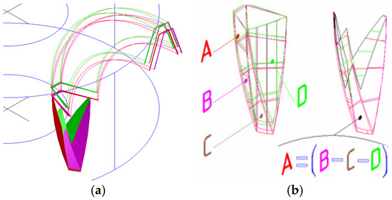
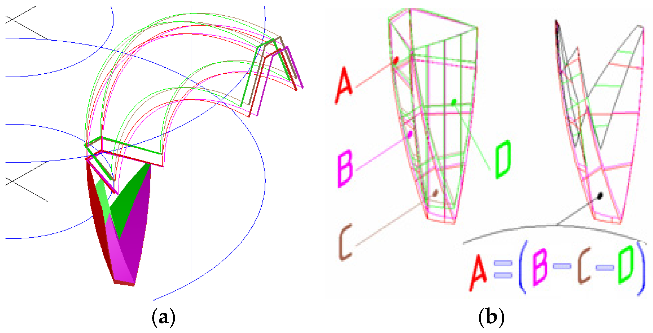
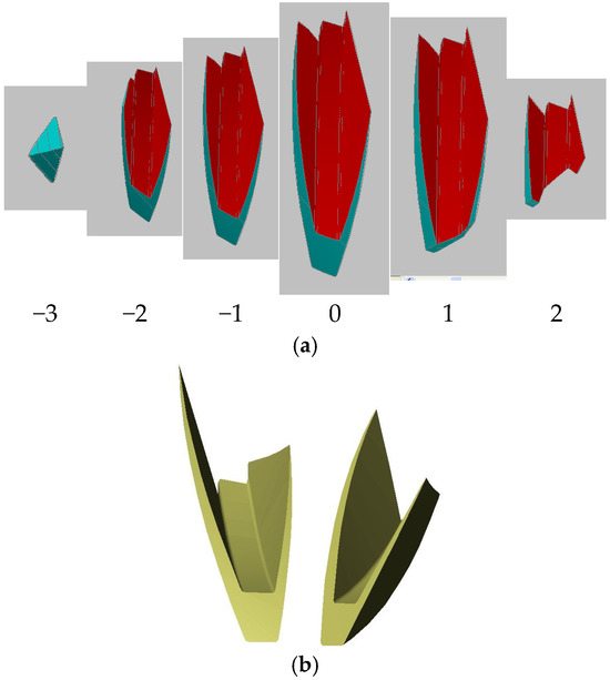
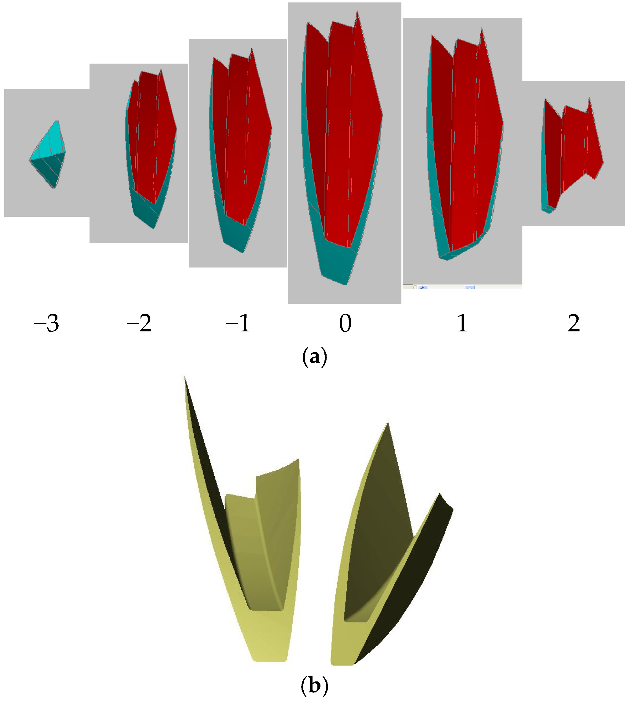
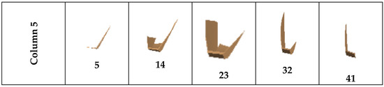
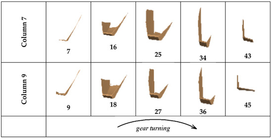
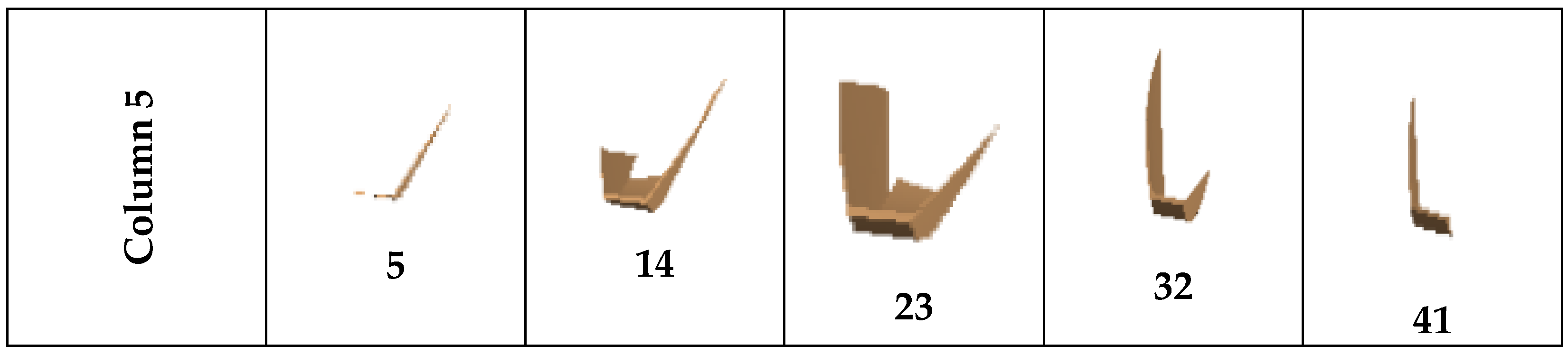
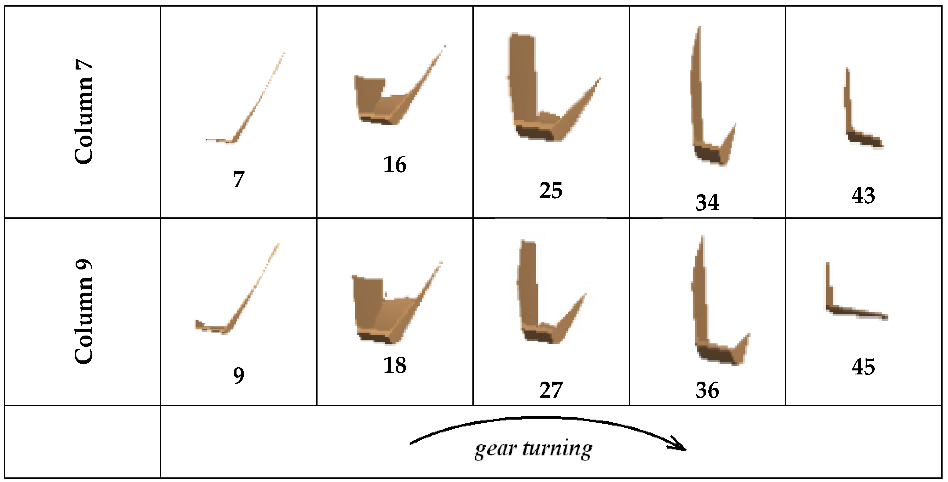
Based on the kinematic diagram of the hobbing process (Figure 2), the rotational movements of the cutter and the workpiece are represented by their spatial traces, or splines [42]. Figure 2a shows their combination in the cutting zone and the formation of spatial chips on this basis. Figure 3 shows typical spatial geometric models of undeformed chips cut by the teeth of one of the nine hob rails (columns) (a) and a model of a chip cut by the central tooth of this rail (b). Figure 4 demonstrates a 3D model of undeformed chip A, which is formed by the intersection of splines; B is the trajectory of the outer contour of the cutting tooth; C is the trajectory of the outer contour of the same tooth when it was in the previous position in the axial feed movement; D is the trajectory of the outer contour of the previous tooth on the helical line of the hob cutter, shifted by the feed per tooth and rotated by a unit roll angle.
Figure 2.
Graphical representation of the algorithm used to form the instantaneous transition surface of a hob tooth by superimposing and intersecting spline surfaces (a); graphical 3D model of the cut layer (b).
Figure 3.
Example of spatial geometric models of chips cut by the teeth of one rack of a hob cutter (a) and a model of a chip cut by the central tooth of this rail (b) [41].
Figure 4.
Geometric models of cut layers on the teeth of a hob helical surface [41].
The number of hob teeth forming one gap can be substantial. For example, if the hob has 9 rails and there are 5 hob teeth in contact with the wheel, then the number of active teeth will be 45, with each tooth cutting in the same area. Accordingly, the number of chips of various shapes and sizes will be 45. Figure 4 shows how the shape and size of the chips cut by the teeth change. The teeth are marked with numbers corresponding to their position on the hob helical surface with a certain step.
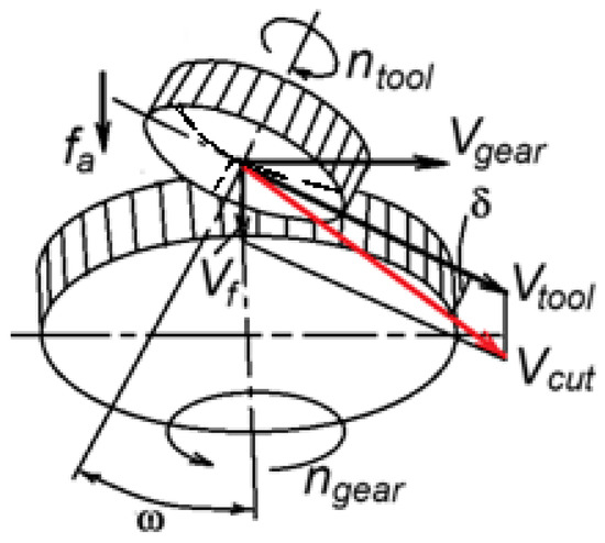
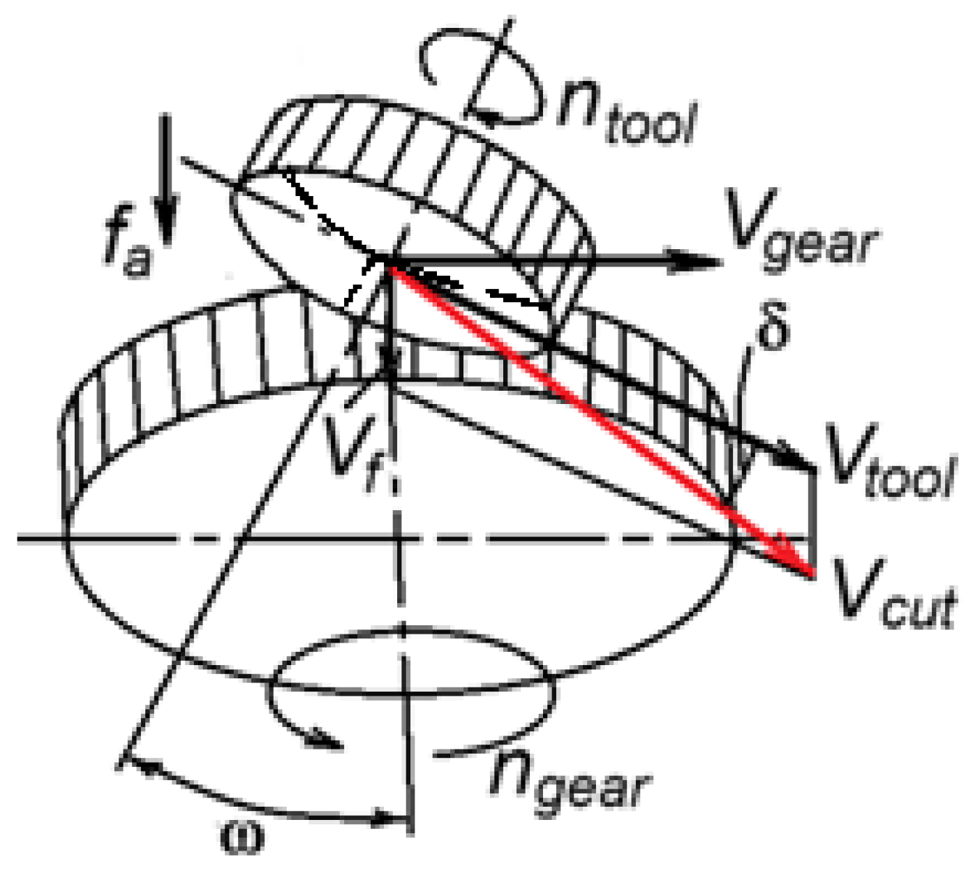
Unlike hob cutting, in the power skiving method, according to its kinematics, all teeth of the disc cutter cut identical chips. As mentioned above, the tool with the machined gear reproduces the meshing of two cylindrical gears, and the cutter axis is inclined relative to the gear axis by an angle ω (Figure 5).
Figure 5.
Kinematic diagram of the power skiving process; ω is the angle of tool and workpiece axes’ intersection, δ is the angle between the vectors Vcut and Vtool, ntool is tool rotation frequency, ngear is workpiece rotation frequency, Vtool is tool speed, Vf is feed speed, fa is axial feed movement, Vgear is the linear speed of the gear, and Vcut is resultant cutting velocity vector.
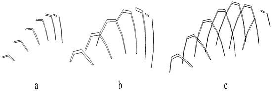
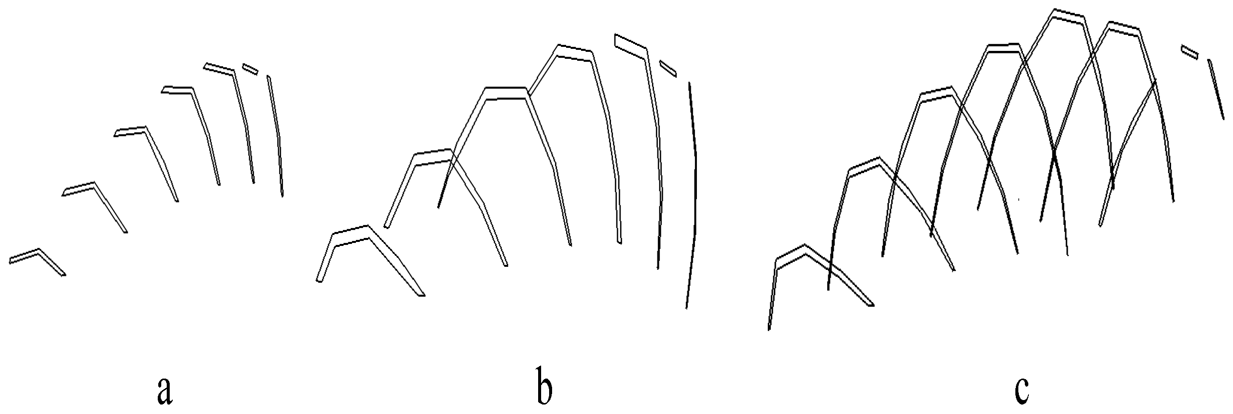
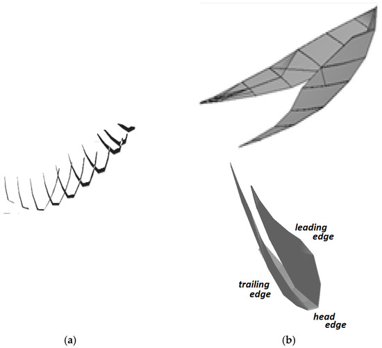
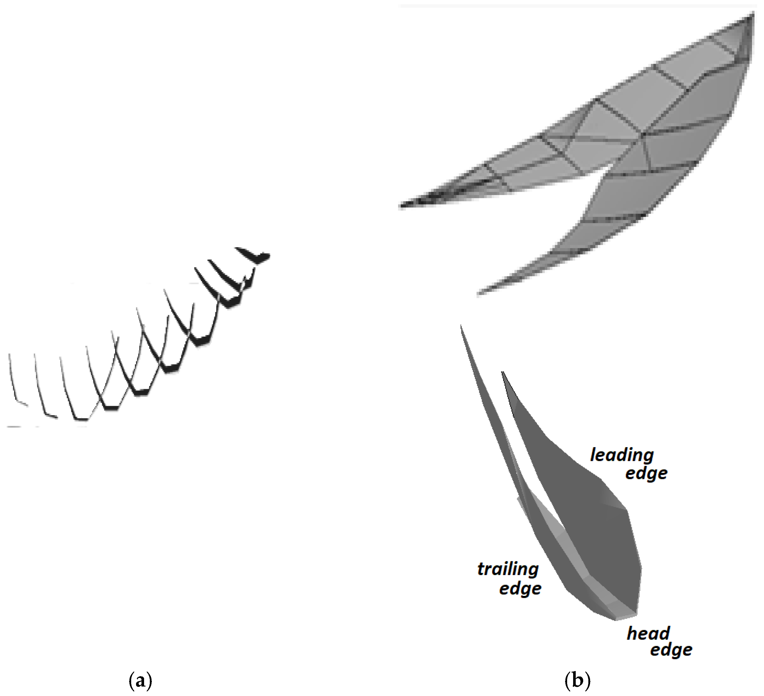
If this caused significant friction in a gear pair, then here, such a crossing of axes creates conditions for cutting. The process of cutting a gear is ensured by the movement of the tool at a speed Vtool and the axial feed movement fa, corresponding to the feed speed Vf, while the linear speed of the gear Vgear is an auxiliary movement that ensures the continuity of the process and is not a cutting movement. The cutting speed is formed as the geometric sum of the vectors Vtool and Vf, but the value of the parameter Vf is orders of magnitude smaller than the value of the parameter Vtool, so the angle δ is close to zero, and the cutting speed vector practically coincides with the linear speed vector of the tool Vtool. The principle of morphology in constructing a geometric model of the cut layer in this and other methods of continuous generation is shown in Figure 6, where different chip structures correspond to different axial feed rates. The integral shape of the chip is formed from the synthesis of its successive instantaneous cross-sections at discrete positions of the tool tooth, which form its ‘skeleton’, as shown in Figure 7. Initial data: module m = 2.5 mm; number of gear teeth Zk = 33, number of cutter teeth Zp = 24; cutting speed is 190 m/min; feed rate 0.75 mm/rev; cutting to full profile height; spindle angle 25°; face angle equal to zero; external cutter diameter 66 mm; gear width 22 mm; cutter tooth angle equal to spindle shaft angle 20°.
Figure 6.
Sequential cross-sections of undeformed chips in three passes (a–c) [43].
Figure 7.
Structure of chips (a) and their 3D model (b) [44].
4. Modeling Cutting Force
When analyzing cutting forces, it is necessary to take the following features common to all gear cutting processes into account:
- ▪
- The parameters of the cut layers on each blade differ and vary depending on the angle of contact between the tooth and the workpiece. This results in a continuous change in the magnitude and direction of the forces acting on the system;
- ▪
- The processes are multi-bladed and intermittent, with cyclic loading of the teeth;
- ▪
- For most of the cutting path of one tooth, two or three blades cut simultaneously, resulting in unfree cutting and increased cutting force;
- ▪
- As a result of the axes of the tool and the workpiece intersecting, the actual (kinematic) angles of the blades change. This leads to a redistribution of the cutting force on the blades, causing asymmetric wear.
The cutting force depends on the parameters of the cut layer, the shear intensity and the strength limit of the gear blank material. This can be represented as the main component of the cutting force, coinciding with the cutting speed vector in direction, and described by the following function:
where Scs is the cross-sectional area of the cut layer, mm2; [τ] is the shear strength limit, MPa; and ξ is the chip compression ratio. For most machining methods, the force Po corresponds to the tangential component Pz of the total cutting force.
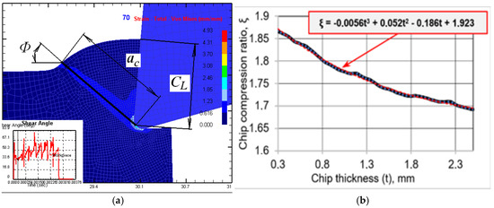
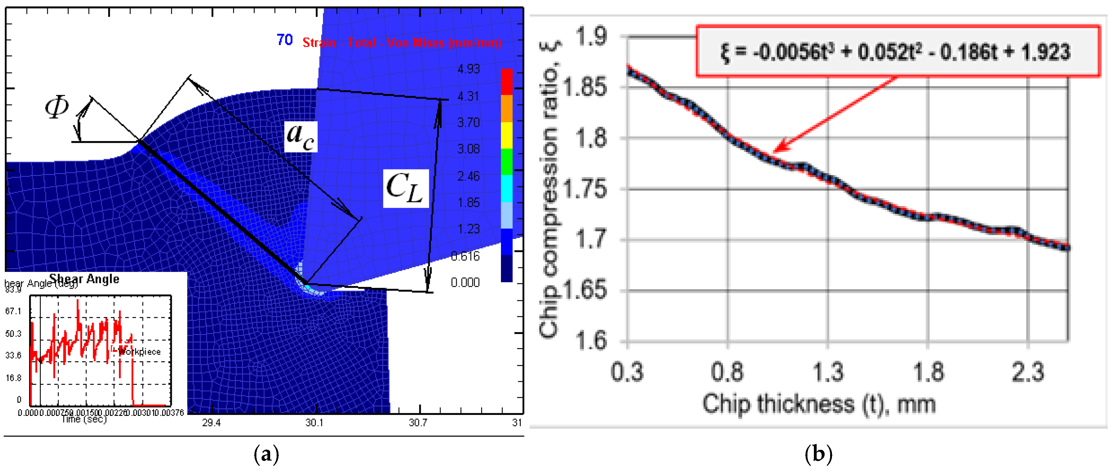
The cross-sectional area in this formula was obtained based on the previous stage of research. To determine the compression coefficient ξ, a rheological analysis method was used with the help of Deform 2D software (DEFORM V13.1) (Figure 8a). This system also makes it possible to establish the dependence of the parameter ξ on the thickness of the cut layer (Figure 8b), which shows that as the thickness of the cut decreases, the intensity of chip compression increases. As the product characterizes the specific cutting force, it is clear that this parameter is not static, but varies depending on the thickness of the cuts. This can be taken into account in our methodology when modeling the cutting force. Having established how the area and thickness of the chips change with the angle of rotation of the tool in a previous study, we can determine the relationship between the cutting force and this angle. As can be seen from the geometric models of chips (Figure 4), one, two, or three blades participate in cutting in different areas of the active zone: the entry, top, and exit blades of the tool tooth.
Figure 8.
Determination of plastic deformation intensity parameters in the cutting process using the Deform 2 system: visualization of rheological analysis of the chip formation process (a); graph of the dependence of the chip shrinkage coefficient on its thickness (b) [44].
This method enables the cutting force to be determined at the level of the individual cutting blade in each method. This is important for evaluating the components of cutting force and torque, as well as their effect on elastic deformations and the accuracy of gear machining.
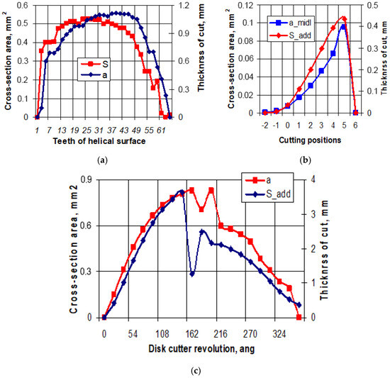
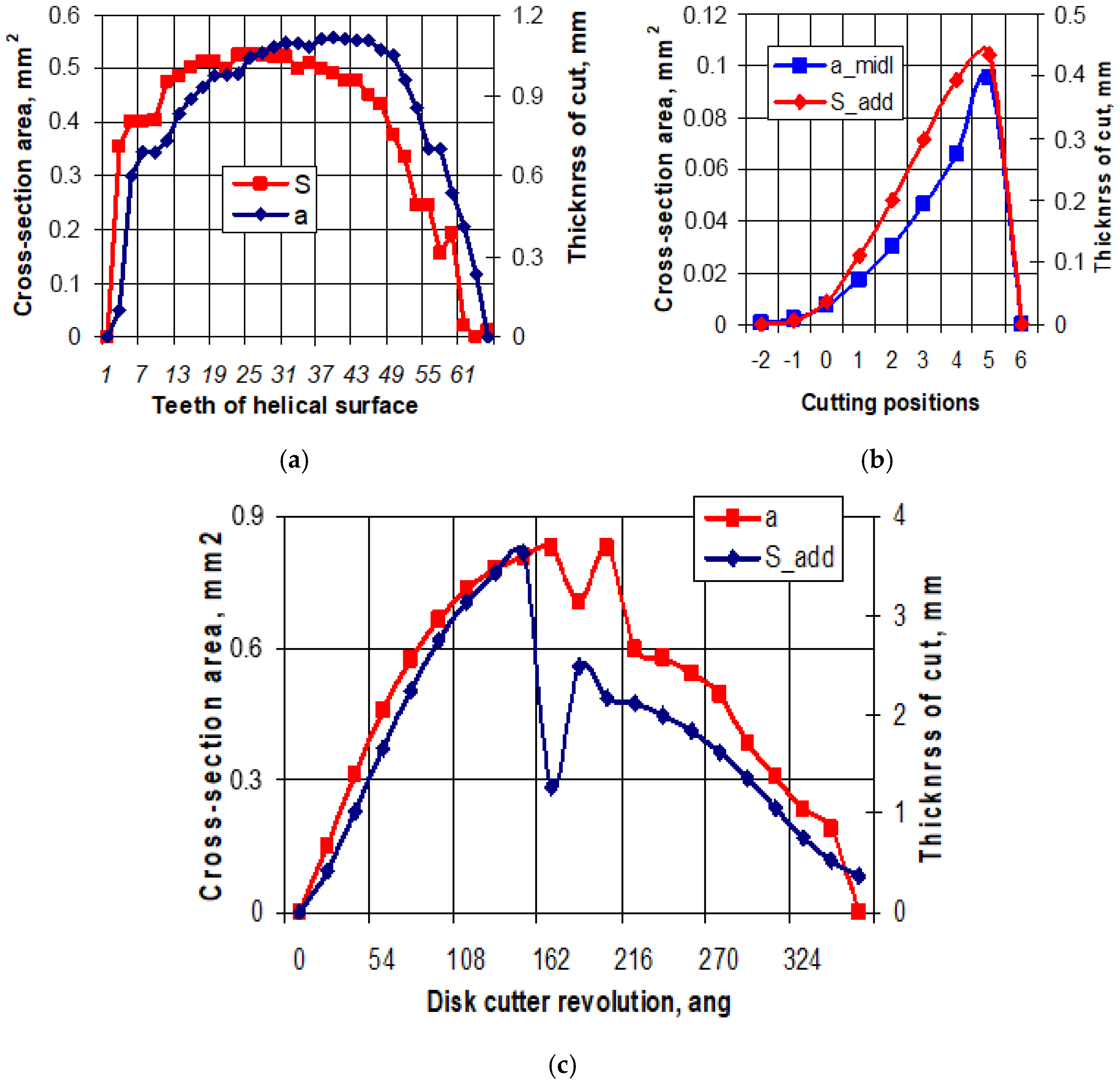
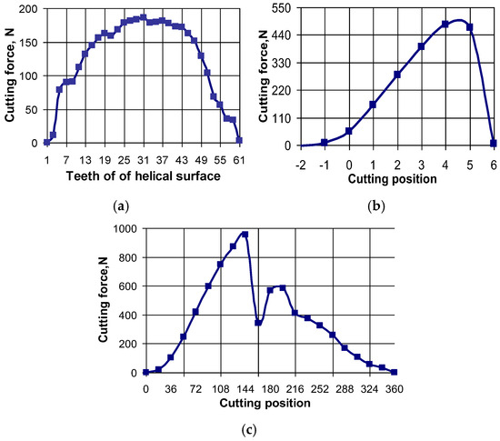
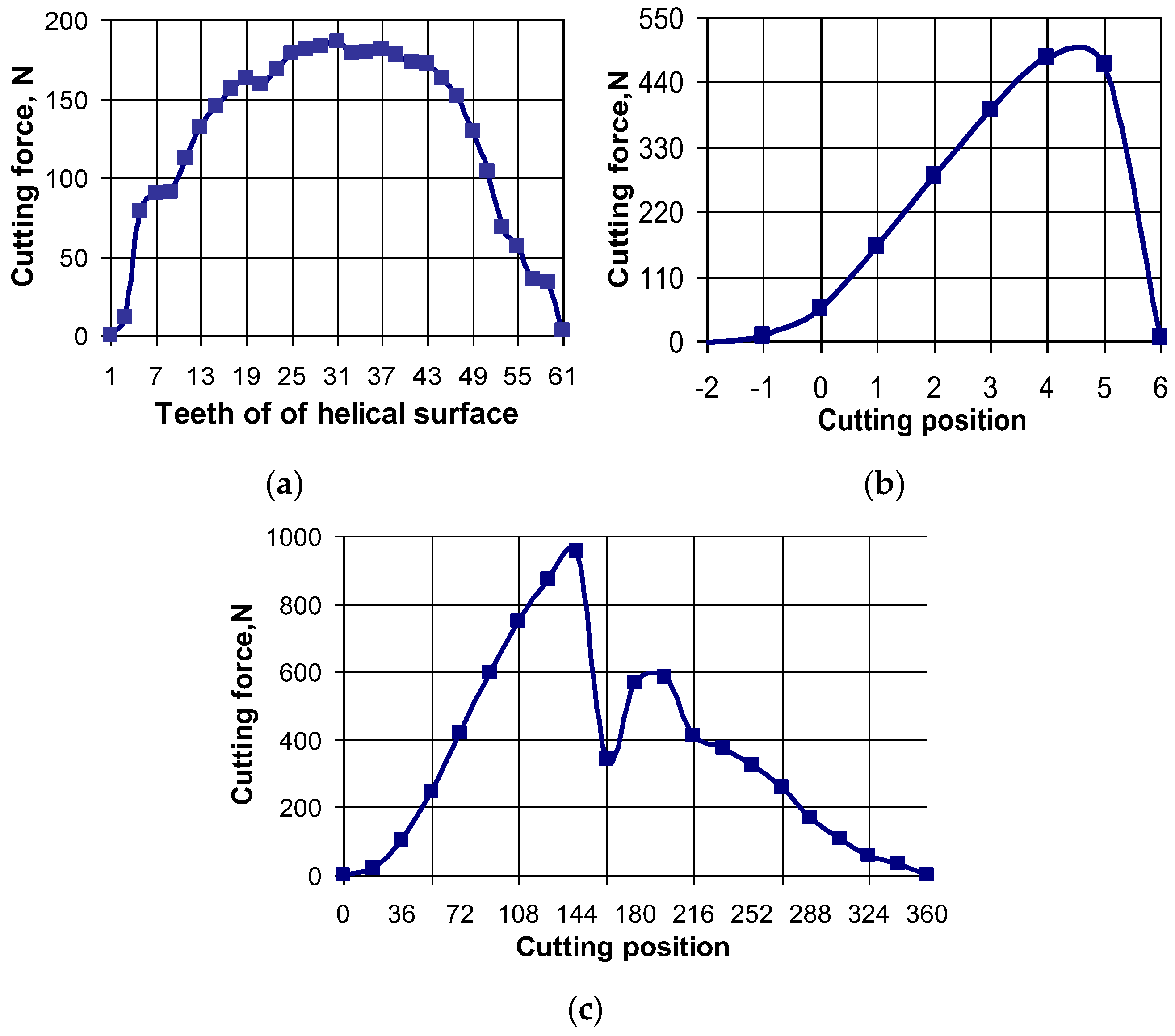
Examples of cutting parameters and forces involved in power skiving are shown in Figure 9. These graphs illustrate how the parameters of the cut layers and the cutting forces on the teeth of the tools change when machining a gap between the gear teeth. Figure 10 shows the total cutting forces (on all active blades) corresponding to these parameters.
Figure 9.
The parameters of the cut layers are determined by: the angle of rotation of the hob (a); the consecutive positions of the skiver cutter teeth (b); the angle of disc cutter’s rotation in RCM (c).
Figure 10.
Continuous cutting force in hobbing (a), in the power skiving process (b) and radial-circular method (c).
Initial data for hob cutting: modulus m = 2.5–5 mm; axial feed f = 0.25 is 0.75 mm/rev; number of wheel teeth Zg = 40–80, number of cutter teeth Zcut = 22–40; the angle of inclination of the screw line of the cutter ω = 20°; tool rotation frequency nc = 1150 min−1; workpiece material is chrome-carbon alloy, strength limit 600 MPa; and shear strength limit [τ] = 300 MPa.
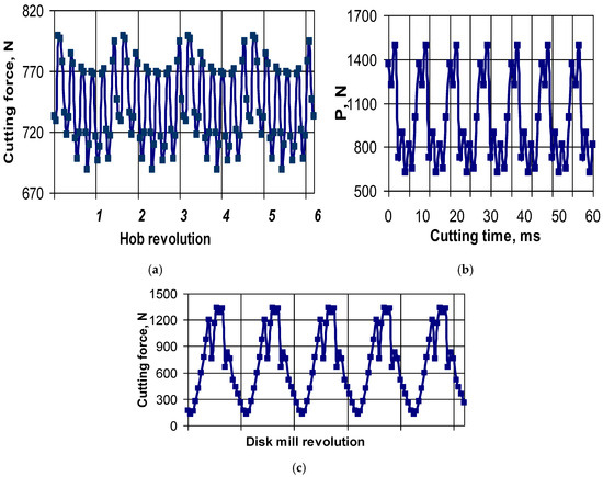
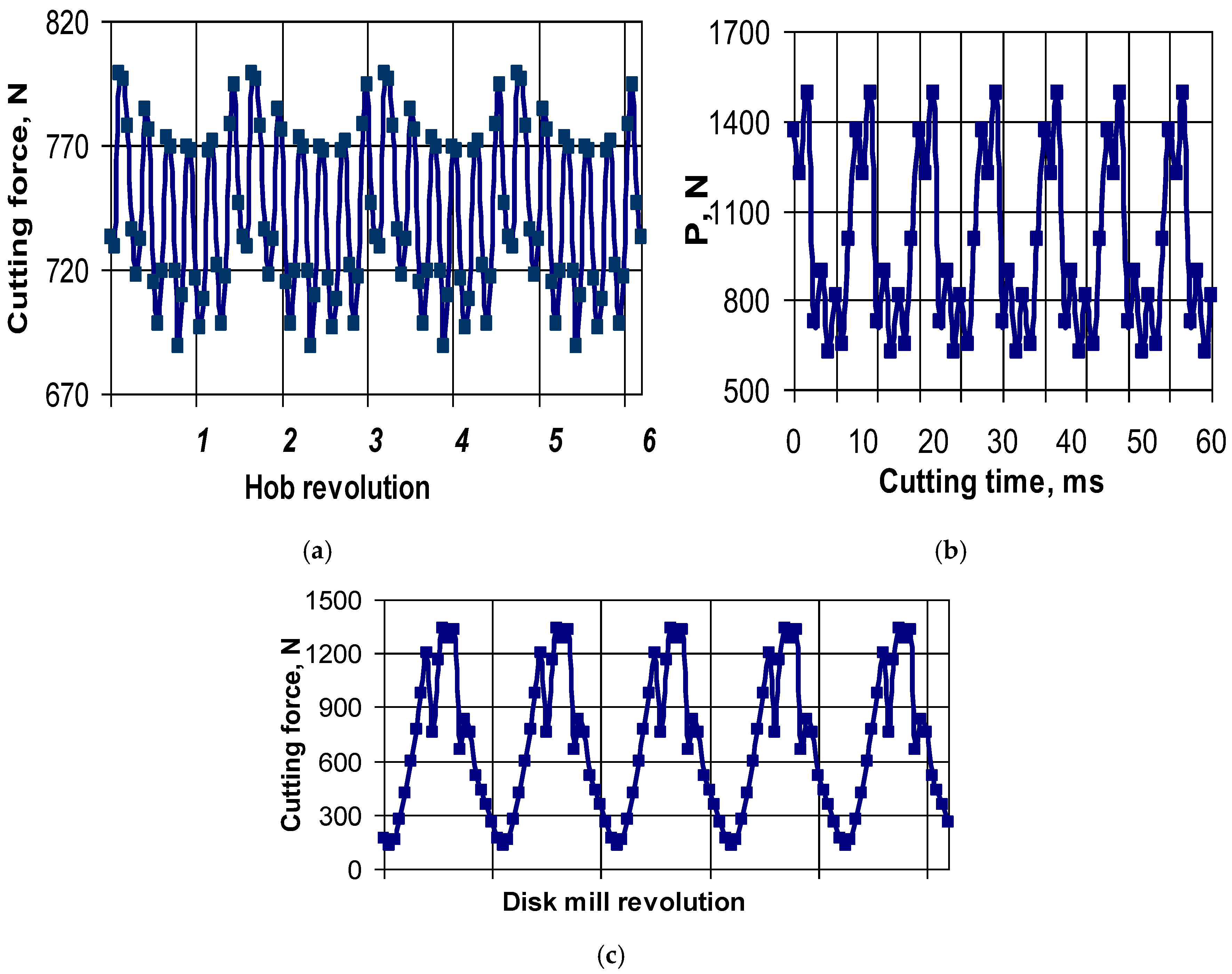
At the same time, all considered cutting types are multi-tooth, i.e., more than one tooth participates in the ‘tool-gear” machine tool engagement. This engagement is characterized by an overlap coefficient equal to the ratio of the length of the active section to the wheel’s angular pitch. In this regard, it is necessary to determine the total cutting force arising on all teeth simultaneously cutting in several gaps, depending on the end overlap coefficient, as shown in Figure 11.
Figure 11.
Total forces involved in multi-tooth cutting in gear machining methods: hob cutting (a); power skiving process (b); radial-circular method (c).
Analysis of these graphs shows that all methods of continuously generating gear surfaces are characterized by intense variations in cutting force. These variations are based on periodic changes in the cut layer parameters, which are repeated in each cycle. Consequently, the machine tool and cutting tool undergo a quasi-static load caused by the average cutting force, as well as a cyclic load caused by an oscillating force with double the amplitude. Consequently, machining errors consist of conditionally constant elastic deformation on the tool–workpiece axis and harmonic oscillation at frequencies that are multiples of the tool’s and gear’s number of teeth.
Attempts have been made to eliminate this drawback in hobbing and power skiving processes. When annual gear production reached its peak in the 1960s and 1970s, the productivity of hob cutting—the main gear cutting process at the time—proved insufficient. Intensive research was therefore conducted to improve the cutting pattern of the hob cutter and increase the productivity of gear cutting processes. The research aimed to reduce the load on the teeth of the hob that removes the maximum amount of stock, since the load on these teeth limits the increase in axial feed. Several cutter designs were developed, including ‘uniform cutting’, ‘equal cut thickness’ and ‘equal chip cross-section’, as well as hob cutters with a parabolic generatrix. However, these designs were ineffective and were not adopted in practice.
One possible partial solution to this problem is to distribute the full height of the hob’s initial tooth contour between two tools, cutting the gear in two passes [45]. During the first pass, the cutter forms the upper part of the gear teeth (addendum), and during the second pass, the lower part (dedendum) is formed. Reducing the height allows 1.5–2 times as many teeth to be formed on the same pitch circle of the hob. This reduces the load and has a positive effect on process dynamics. This concept has been incorporated into the design of taps for cutting threads in two to three passes, as well as into the design of disc skiving cutters [46].
5. Thermal Processes and Their Analysis. Heat and Cutting Temperature
Modeling the heat generated during the cutting process is significant because heat is the main cause of tool wear. The tool material’s properties change if the temperature of the blades approaches the critical point due to heating, causing it to lose its hardness and strength. This can manifest as microcracks spreading through the macro volume, causing chipping and breaking of the blades, or as plastic flow. Since heat is the result of cutting and friction, the basis for its calculation is the cutting and friction forces acting on the tool surfaces.
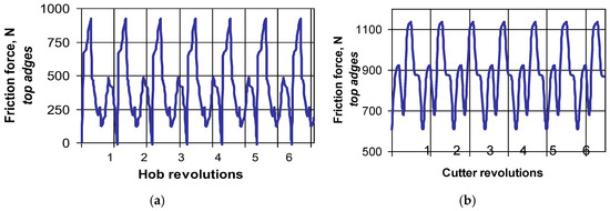
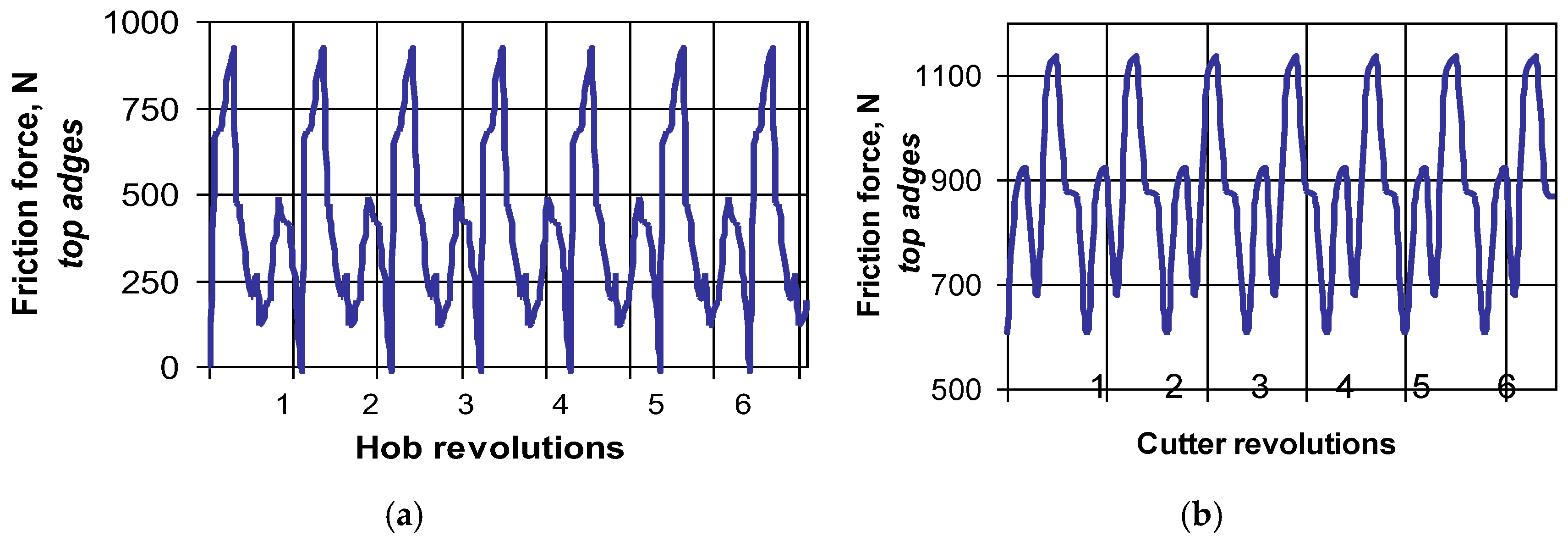
As is well understood in metal cutting theory, the significant intensity of the secondary plastic deformation of the chips causes the friction on the tool face to be non-Coulombian. As it is difficult to predict the actual value of this coefficient, it was assumed to be equal to one. The coefficient of friction on the clearance surface of the tool can be determined for metal-to-metal interaction conditions using the Deform 2D system (DEFORM V13.1), depending on the cutting speed. For example, at a cutting speed of 45–60 m/min for a high-speed cutting tool, the friction coefficient is 0.6–0.63. Figure 12 shows the friction forces in hobbing and in the power skiving for these values, corresponding to the initial conditions given above.
Figure 12.
Friction forces in hobbing (a) and in the power skiving (b).
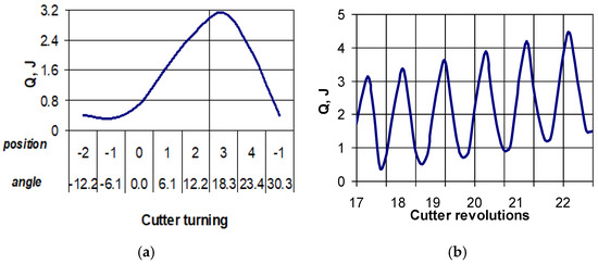
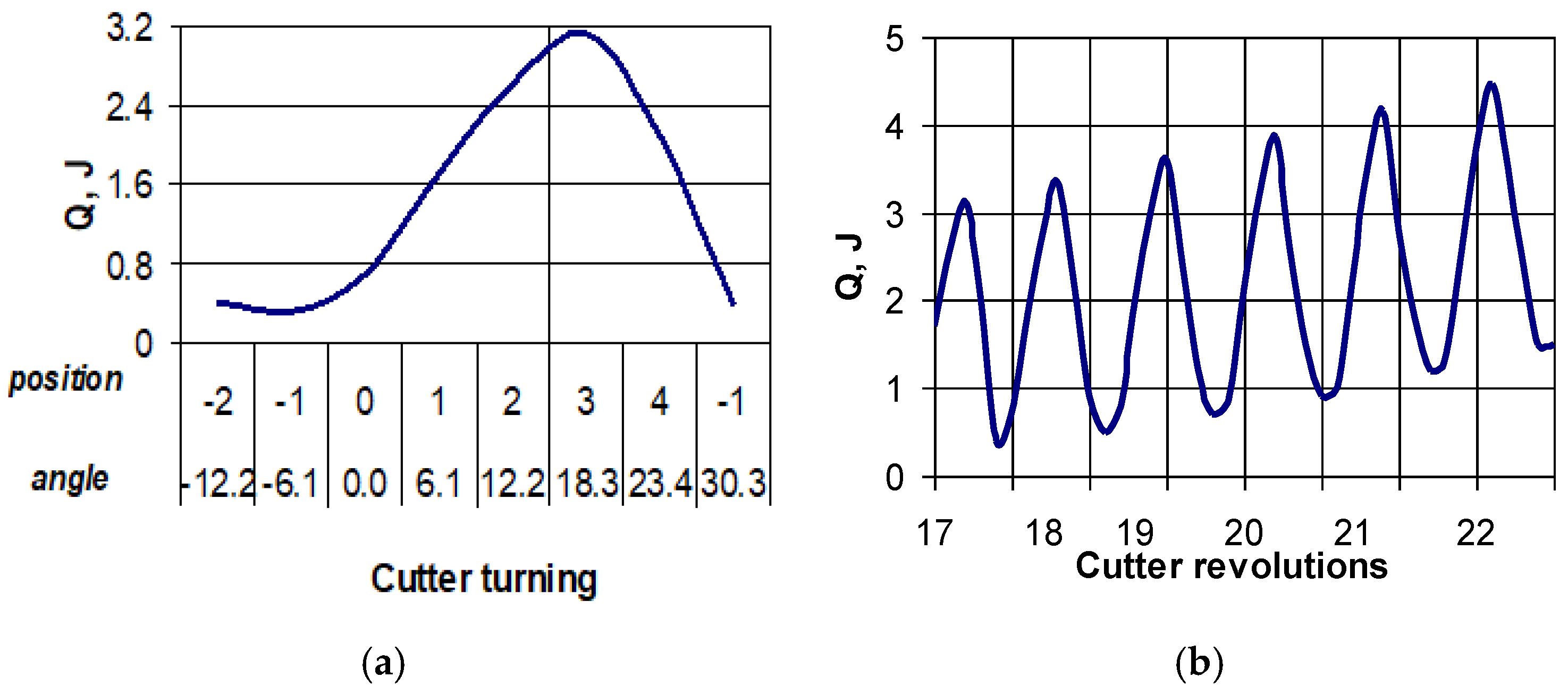
Based on the calculated friction forces acting on the face and clearance surfaces of the tool teeth, we can determine the cutting heat, which is equal to the sum of the partial work involved in shearing and friction (Figure 13a). This heat is distributed between the tool, the chips and the workpiece, and is also transferred to the environment. As power skiving is a high-speed process, it can be assumed that the heat distribution balance is the same as in grinding, where up to 10% of the cutting heat is transferred to the tool.
Figure 13.
Tool temperature and its change over time during power skiving: temperature change on one tooth of a carbide milling cutter during one complete revolution of the tool (a); heat accumulation and change in peak temperatures (b).
For a single tooth, the cutting process is repeated at the same frequency as the skiver tool’s rotation. Due to heat transfer, heat from the top of the cutting wedge spreads into the body of the tool at a rate determined by its thermal conductivity coefficient (58 W/(m·°C) for steel), which is the primary source of heat dissipation.
The second source of cooling is contact with air. Cutting cycles alternate with free running when the tooth comes into contact with the environment and cools down, since no liquids are used for hard alloys, which are the main tool material in the power skiving method. At high rotation speeds of around 1100–1800 m−1, air cooling of the tool is highly effective, and the heat energy dissipation due to the combined action of these two factors will be within the range of 93–95%. Nevertheless, a gradual accumulation of heat in the tooth body will occur during the process of completely cutting through the gap across the entire width of the gear rim and repeating the cycle multiple times, as shown in Figure 14 for the final passes of cutting the wheel. Accordingly, the temperature of the tool will also increase with each revolution. Initial data: the modulus is 2.5 mm; cutting speed is 220 m/min; axial feed is 0.75 mm per revolution of the workpiece; number of teeth of the gear is 33, number of teeth of the tool is 24; gear parameters: tooth height is 5.6 mm, rim width is 12 mm; transmission ratio of machine tool gearing is 1.38; and the number of cycles (tool revolutions) for cutting full height is 22.
Figure 14.
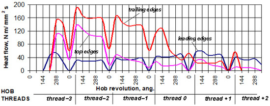
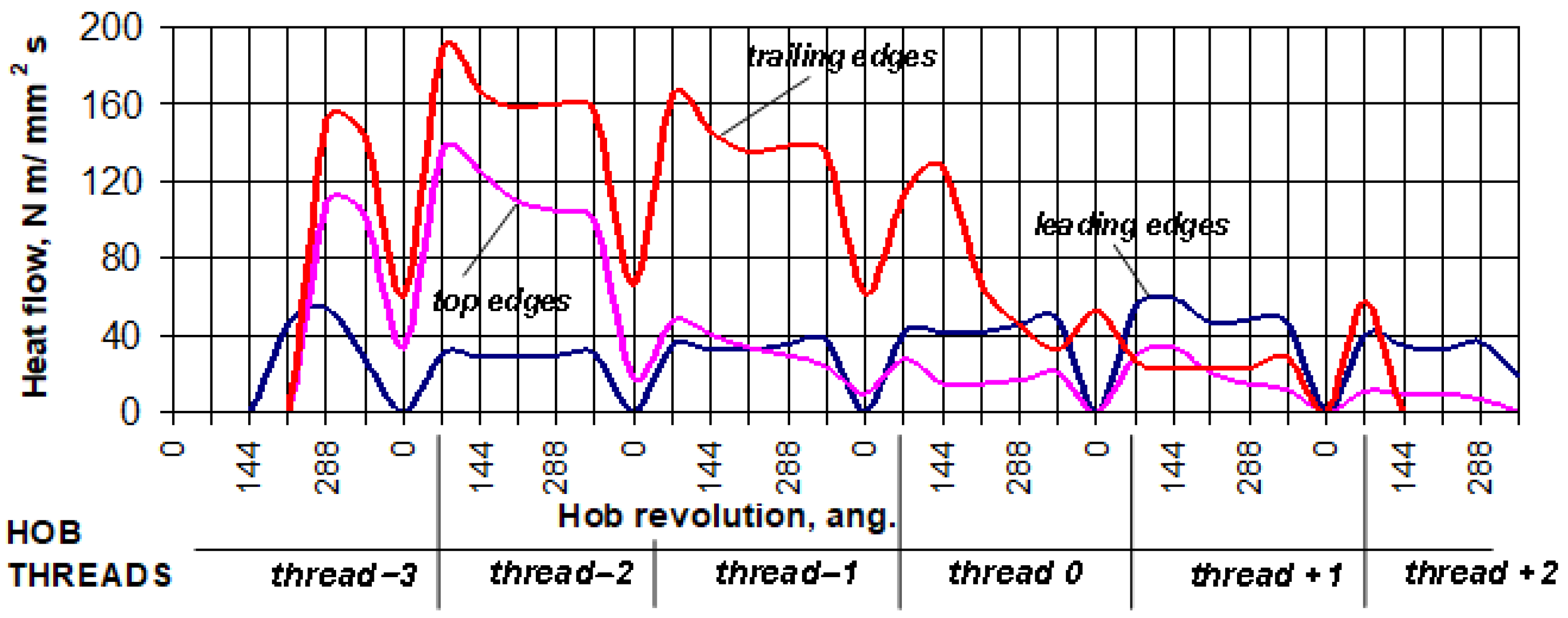
Heat flows on the blades of the hob teeth on the active part of its helical surface.
In addition to heat, the cutting process also involves heat flows that arise between the bodies involved as a result of thermal conductivity, reflecting the thermal state of the tool.
As a function of the friction forces on the contact surfaces of the tool, heat flows into the cutting tool occur at the points of contact between the chip and the tool on the face surface () and between the tool and the machined surface of the part on its clear surface ():
The intensity of the heat flux on the rear surface is described by the following equation:
where V is cutting speed, m/s; is the width of the contact area between the chip and the face, mm; its value can be determined using the Abuladze formula [47]:
is the width of the contact area between the clearance surface and the processed surface, can be taken as equal to the maximum permissible wear width of the tool on this surface; for hobs, this is 0.2–0.4 mm; and b is the cut width, for the top blade of a hob cutter b = 0.64 m.
The value V/ξ characterizes the speed of the chip’s movement along the face, which slows down due to secondary deformation of the chip in proportion to the chip compression ratio ξ. Heat flows on the teeth blades of the hob on the active part of its helical surface are shown in Figure 14.
6. The Temperature of the Cutting Wedge
Both characteristics, cutting heat and heat flows, can be used for the next stage of modeling, namely, predicting the temperature of the cutting blade.
As a function of heat QΣ (Joules), temperature can be determined based on the following considerations. During heat transfer, the temperature of a body depends on the mass m (kg), which absorbs this heat, and the specific heat capacity of the material ω of the instrument:
for steel ω = 452 Joules/(kg ⋅ °C).
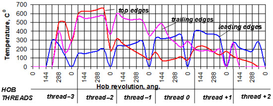
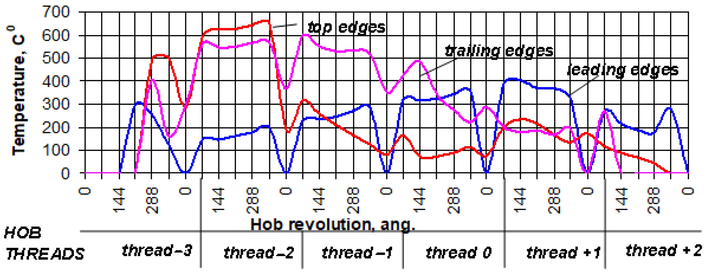
We will consider the mass of the blade volume as formed by the contact area Cγ of the chip with the front surface of the tool, the wear area on the clearance surface Cα, and the length equal to the width of the blade. Based on the Formula (3) in Figure 15, the temperature that occurs at the top and side edges of the hob teeth along its helical surface is shown.
Figure 15.
Temperature distribution on the blades of the hob teeth on the active part of its helical surface.
The results of the heat flow study of tooth surfaces enable the average and maximum blade temperatures to be calculated.
The basic principles of thermophysics were used to calculate temperatures based on heat flows. According to these principles, the heat source is assumed to be fast-moving and uniformly distributed over the surface of the cutting wedge:
where λ0 is thermal conductivity coefficient of tool material, Joules/mm·s·°C; χ is temperature conductivity coefficient of the tool material, mm2/s; q is heat source intensity, Joules/sm2·s; b is linear length of the source, equal to the active width of the blade, mm; V is cutting speed, mm/s; Ksh is shape factor of a fast-moving source.
The thermophysical properties of the tool and workpiece materials are assumed to be the same: λ = 0.4 Joules/mm·s · °C; χ = 6.6–7.2 mm2/s; Ksh = 1.
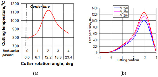
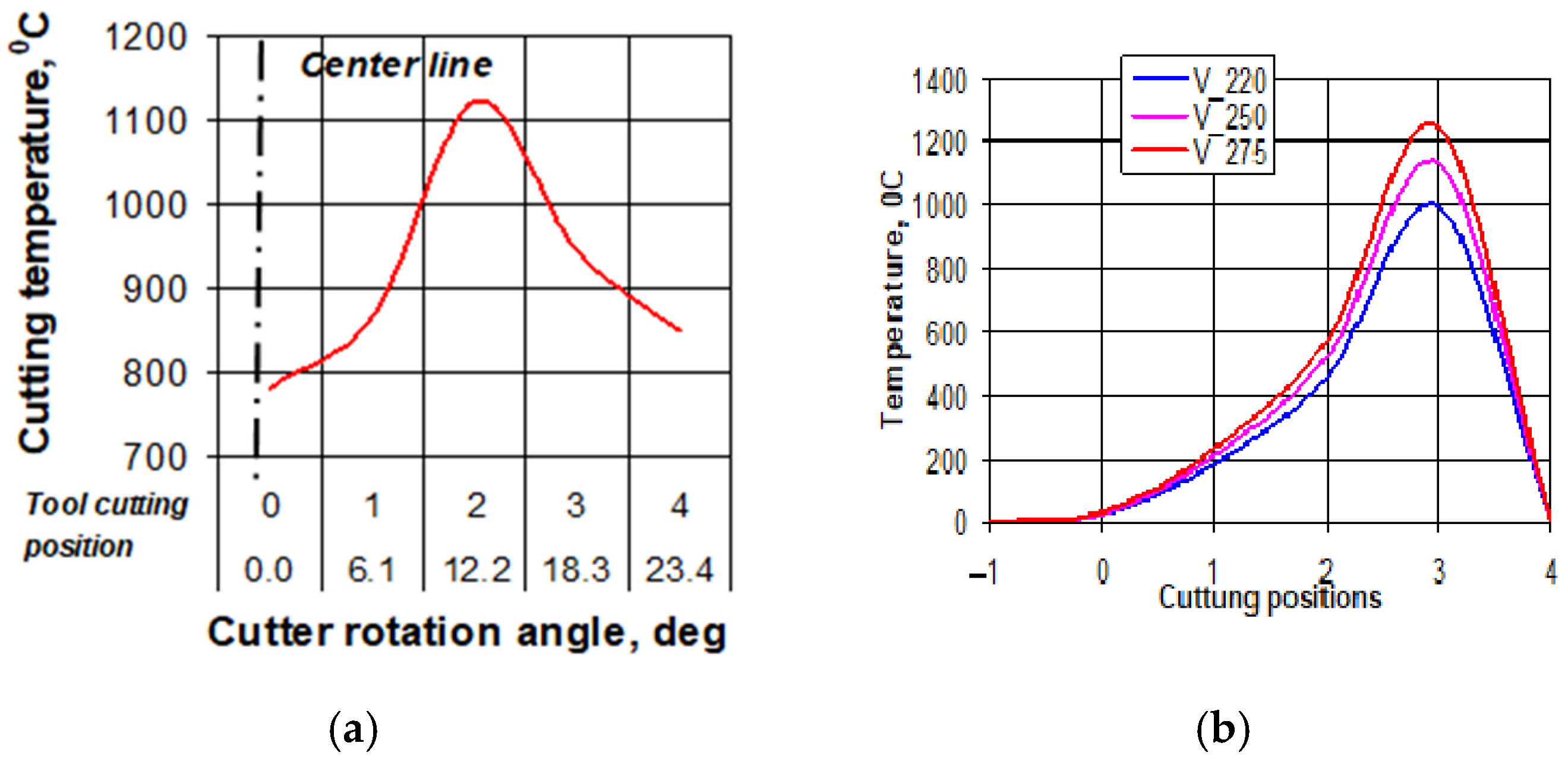
Based on the above data and the specified parameters λ and χ, Figure 16a shows the temperature generated during the power skiving process on one tooth of a carbide cutter, as it rotates, and Figure 16b shows the relationship between the temperature and the tooth of the skiver cutter during one revolution, as a function of cutting speed.
Figure 16.
Dependence of the temperature on the skiver-cutter tooth on the angle of rotation (a) and on the cutting speed (b).
Thermal process modeling shows that, in hobbing, the maximum temperature occurs at the tip and trailing edges of the teeth cutting in the entry area near the line of centers. This value is close to the 750° temperature strength limit of high-speed steels, the main material used for these cutters. At the same time, the combined effect of the heat generated by the trailing and leading blades, as well as a top blade reaching the entry and exit tips of the teeth, will cause the temperature to rise above the temperature stability limit. Therefore, the operating conditions must be adjusted by reducing the cutting speeds or by changing the tool material.
The temperature during power skiving (Figure 16) at a cutting speed of 275 m/min is at the limit of temperature resistance for hard alloys (about 1250 °C), but taking into account the phenomenon of heat accumulation (Figure 14), this cutting mode should also be reduced.
When modeling heat, it is important to note that we must establish a heat balance between the bodies involved in cutting. This means that we need to know the percentage of heat that will be transferred to the tool. The most effective way to solve this problem is to obtain experimental data. However, this method is labor-intensive and is therefore best used to verify the results of theoretical calculations in the final stage of research. By contrast, the second approach, which is based on the calculation of heat flows and temperature prediction, is more rational and based on proven dependencies.
7. Conclusions
A system has been developed for the sequential calculation of a range of parameters and systematic forecasting of the condition of gear-cutting machine tools based on comprehensive modeling of the main continuous methods of generating gear-cutting. The comprehensive approach is based on the sequence and interconnection of processes and phenomena that accompany gear cutting, from chip formation to deformation, tribological, force and thermal characteristics in stationary and dynamic states. The construction of 3D models of cut layers is based on a logical system that corresponds to the kinematics of a specific gear-cutting method, as well as a mathematical description of splines reproducing the movement of form-forming surfaces. The modeling processes use widely available standard application packages such as AutoCAD 2024, SolidWorks 2024, Deform 2D (DEFORM V13.1) and Simulink Matlab R2025a. The developed system optimizes and rationalizes technological and design parameters, including cutting modes, tool and equipment geometry, and parameters, at each research stage. This ensures the specified machining accuracy, surface quality, and tool wear are achieved while minimizing the time and cost of organizing gear production. To enhance the reliability of the research findings, it is planned to organize and carry out experimental work to analyze and verify a number of parameters used in theoretical calculations, in particular the chip deposition coefficient, fluctuations in cutting force, friction coefficients and the heat balance in the cutting zone.
The implementation of the developed interrelated models in production conditions makes it possible to reduce the design time for labor-intensive, multi-factor, multi-parameter and multi-purpose gear cutting operations by 25–30% and to increase the effectiveness of the decisions made by 12–15%.
Author Contributions
Conceptualization, I.H. and P.P.; methodology, I.H. and M.V.; software, I.H.; validation, M.V. and I.H.; investigation, I.H. and. P.P.; writing—original draft preparation, M.V. and P.P.; writing—review and editing, I.H. and P.P.; visualization, M.V. and I.H.; project administration, P.P. and M.V.; funding acquisition, P.P. and M.V. All authors have read and agreed to the published version of the manuscript.
Funding
This research received no external funding.
Data Availability Statement
The original contributions presented in the study are included in the article.
Conflicts of Interest
The authors declare no conflicts of interest.
References
- Verified Market Research. Global Gear Technology Market by Technology by Geographic Scope and Forecast; Verified Market Research: Lewes, DE, USA, 2021; Available online: https://www.verifiedmarketresearch.com/product/gear-technology-market (accessed on 25 February 2026).
- Bouzakis, K.; Kombogiannis, S.; Antoniadis, A.; Vidakis, N. Gear hobbing cutting process simulation and tool wear prediction models. J. Manuf. Sci. Eng. 2002, 124, 42–51. [Google Scholar] [CrossRef] [Scilit]
- Dimitriou, V.; Vidakis, N.; Antoniadis, A. Advanced Computer Aided Design Simulation of Gear Hobbing by Means of Three-Dimensional Kinematics Modeling. J. Manuf. Sci. Eng. 2007, 129, 911–918. [Google Scholar] [CrossRef] [Scilit]
- Karpuschewski, B.; Knoche, H.J.; Hipke, M.; Beutner, M. High performance gear hobbing with powder-metallurgical high-speed-steel. Procedia CIRP 2012, 1, 196–201. [Google Scholar] [CrossRef] [Scilit]
- Klocke, F.; Brecher, C.; Löpenhaus, C.; Ganser, P.; Staudt, J.; Krömer, M. Technological and Simulative Analysis of Power Skiving. Procedia CIRP 2016, 50, 773–778. [Google Scholar] [CrossRef] [Scilit]
- Tapoglou, N. Calculation of non-deformed chip and gear geometry in power skiving using a CAD-based simulation. Int. J. Adv. Manuf. Technol. 2019, 100, 1779–1785. [Google Scholar] [CrossRef] [Scilit]
- Vargas, B.; Zapf, M.; Klose, J.; Zanger, F.; Schulze, V. Numerical modelling of cutting forces in gear skiving. Procedia CIRP 2019, 82, 455–460. [Google Scholar] [CrossRef] [Scilit]
- Inui, M.; Huang, Y.; Onozuka, H.; Umezu, N. Geometric simulation of power skiving of internal gear using solid model with triple-dexel representation. Procedia Manuf. 2020, 48, 520–527. [Google Scholar] [CrossRef] [Scilit]
- Stadtfeld, H.J. Power Skiving of Cylindrical Gears on Different Machine Platforms. Gear Technol. 2014, 1, 52–62. [Google Scholar]
- Bouzakis, K.; Chatzis, S.; Kombogiannis, O.; Friderikos, O. Effect of chip chip geometry and cutting kinematics on the wear of coated PM HSS tools in milling. In Proceedings of the 7th International Conference Coatings in Manufacturing Engineering, Kallithea, Greece, 1–3 October 2008; pp. 197–208. [Google Scholar]
- Tapoglou, N.; Antoniadis, A. Hob3D: A Novel Gear Hobbing Simulation Software. In Proceedings of the World Congress on Engineering (WCE 2011), London, UK, 6–8 July 2011. [Google Scholar]
- Tapoglou, N.; Belis, T.; Vakondios, D.; Antoniadis, A. CAD-Based Simulation of Gear hobbing. In Proceedings of the 31 International Symposium on Mechanics and Materials, Chania, Greece, 9–14 May 2010. [Google Scholar]
- Bouzakis, K.; Lili, E.; Michailidis, N.; Friderikos, O. Manufacturing of cylindrical gears by generating cutting processes: A critical synthesis of analysis methods. CIRP Ann. 2008, 57, 676–696. [Google Scholar] [CrossRef] [Scilit]
- Monden, T.; Kikuchi, T.; Yoshikava, K. Super Skiving Cutter An Innovative Process Modification for Gear Skiving. Mitsubishi Heavy Ind. Tech. Rev. 2019, 56, 1–7. [Google Scholar]
- Hideaki, O.; Tayama, F.; Huangb, Y.; Inuib, M. Cutting force model for power skiving of internal gear. J. Manuf. Process. 2020, 56, 1277–1285. [Google Scholar] [CrossRef] [Scilit]
- Rech, J. Influence of cutting edge preparation on the wear resistance in high speed dry gear hobbing. Wear 2006, 261, 505–512. [Google Scholar] [CrossRef] [Scilit]
- Claudin, C.; Rech, J. Development of a new rapid characterization method of hob’s wear resistance in gear manufacturing-Application to the evaluation of various cutting edge preparations in high speed dry gear hobbing. J. Mater. Process. Technol. 2009, 29, 5152–5160. [Google Scholar] [CrossRef] [Scilit]
- Stein, S.; Lechthaler, M.; Krassnitzer, S.; Albrecht, K.; Schindler, A.; Arndt, M. Gear Hobbing: A Contribution to Analogy Testing, and its Wear Mechanisms. Procedia CIRP 2012, 1, 220–225. [Google Scholar] [CrossRef] [Scilit]
- Hoffmeister, B. Uber den Verschleiss am Wolzfraser. Doctoral Dissertation, RWTH Aachen University, Aachen, Germany, 1970. Available online: https://publications.rwth-aachen.de/record/824792/files/824792.pdf (accessed on 25 February 2026).
- McCloskey, P.; Katz, A.; Berglind, L.; Erkorkmaz, K.; Ozturk, E.; Ismail, F. Chip geometry and cutting forces in gear power skiving. CIRP Ann. 2019, 68, 109–112. [Google Scholar] [CrossRef] [Scilit]
- Rech, J.; Djouadi, M.A.; Picot, J. Wear resistance of coatings in high speed gear hobbing. Wear 2001, 250, 45–53. [Google Scholar] [CrossRef] [Scilit]
- Dimitriou, V.; Antoniadis, A. CAD-based simulation of the hobbing process for the manufacturing of spur and helical gears. Int. J. Adv. Manuf. Technol. 2009, 41, 347–357. [Google Scholar] [CrossRef] [Scilit]
- Kacal, A.; Gulesin, M.; Ulaş, H. System design and manufacturing for measurement of cutting forces in gear hobbing process. J. Fac. Eng. Archit. Gazi Univ. 2010, 23, 795–800. [Google Scholar]
- Radzevich, S.P.; Storchak, M. Advances in Gear Theory and Gear Cutting Tool Design; Springer International Publishing: Cham, Switzerland, 2022. [Google Scholar]
- Troß, N.; Brimmers, J.; Bergs, T. Calculation of the maximum chip thickness for a radial-axial infeed in gear hobbing. Procedia CIRP 2021, 99, 232–236. [Google Scholar] [CrossRef] [Scilit]
- Antoniadis, A. Gear skiving—CAD simulation approach. Comput. Aided Des. 2012, 44, 611–616. [Google Scholar] [CrossRef] [Scilit]
- Antoniadis, A.; Vidakis, N.; Bilalis, N. A simulation model of gear skiving. J. Mater. Process. Technol. 2004, 146, 213–220. [Google Scholar] [CrossRef] [Scilit]
- Zhengyang, H.; Chuang, J.; Jing, D.; Xiaozhong, D.; Longlong, G. Optimization of tool design and cutting angles in face gear power skiving. J. Braz. Soc. Mech. Sci. Eng. 2026, 48, 110. [Google Scholar] [CrossRef] [Scilit]
- Shih, Y.-P.; Lee, Y.-H.; Chen, K.-H.; Wang, Y.-C.; Yu-Hsien, W. Feed Rate Improvement for Face Hobbing on a Six-Axis CNC Bevel Gear-Cutting Machine. J. Manuf. Sci. Eng. 2025, 147, 091002. [Google Scholar] [CrossRef] [Scilit]
- Guo, E.; Zhang, H.; Ding, W.; Wang, B.; Yuan, Y. Skiving method for chamfering and deburring of cylindrical gears using two disk tools. J. Manuf. Process. 2025, 144, 93–103. [Google Scholar] [CrossRef] [Scilit]
- Shang, Z.; Zhou, J.; Huang, K.; Fu, C.; Yu, J.; Qian, J.; Shang, Z.; Zhou, J. Research on 3D tooth flank topography of face-hobbed spiral bevel gears incorporating dynamic characteristics of machine tool. Mech. Syst. Signal Process. 2025, 241, 113476. [Google Scholar] [CrossRef] [Scilit]
- Li, Z.; Li, G.; Xu, K.; Xiao, Y.; Wang, L. Multi-degree-of-freedom thermal error modeling of rotary worktable based on three-dimensional spatiotemporal temperature information. J. Manuf. Process. 2025, 143, 56–78. [Google Scholar] [CrossRef] [Scilit]
- Zhang, H.; Xiang, S.; Li, N.; Yang, J. Thermal error mechanism model and transient thermal characteristics analysis of direct-drive rotary axis transmission system of CNC machine tools. Mech. Syst. Signal Process. 2025, 233, 112792. [Google Scholar] [CrossRef] [Scilit]
- Kumar, D.A.; Murugarajan, A.; Prabhu, M.; Pratheesh, K. Effect of Cutting Parameters and Cooling Conditions on Surface Roughness and Tool Wear in Turning Ti-6Al-4V Titanium Alloy on an All-Gear Lathe: A Full Factorial Experimental Study. J. Mater. Eng. Perform. 2025, 34, 28707–28725. [Google Scholar] [CrossRef] [Scilit]
- Zhang, Y.; Duan, C.; Zhou, H.; Wang, Z. Design method for controlling gear surface cutting textures to reduce noise. Proc. Inst. Mech. Eng. Part B J. Eng. Manuf. 2026, 240, 62–74. [Google Scholar] [CrossRef] [Scilit]
- Zhao, Y.; Yao, S. Step-dependent machining uncertainty modeling for the process route and application in the machining of the ring-gear. CIRP J. Manuf. Sci. Technol. 2025, 63, 170–184. [Google Scholar] [CrossRef] [Scilit]
- Li, J.; Wang, C.; Li, Z.; Sun, Y.; Tang, C.; Zou, T. Large eddy simulation and process research on abrasive flow precision machining of transmission spiral bevel gear. Proc. Inst. Mech. Eng. Part B J. Eng. Manuf. 2025, 239, 2098–2111. [Google Scholar] [CrossRef] [Scilit]
- Men, L.; Cai, A. Research on the mechanism of concave error in shaving tooth with multi-source and multi-factor coupling. Adv. Mech. Eng. 2025, 17, 1–16. [Google Scholar] [CrossRef] [Scilit]
- Chen, Y.; Yang, J.; Ding, W.; Du, Z.; Liu, J. Optimization of energy-saving machining parameters of gear grinding based on NSGA-II-TOPSIS method. Int. J. Interact. Des. Manuf. 2025, 19, 8729–8745. [Google Scholar] [CrossRef] [Scilit]
- Hrytsay, I.; Topchij, V.; Kuk, A. Computer 3D Modelling of Chip Geometry and Force Field in the Hobbing Process. Ukr. J. Mech. Eng. Mater. Sci. 2018, 1, 68–79. [Google Scholar] [CrossRef] [Scilit]
- Hrytsay, I.; Stupnytskyy, V.; Topchii, V. Improved Method of Gear Hobbing Computer Aided Simulation. Arch. Mech. Eng. 2019, 66, 475–494. [Google Scholar] [CrossRef] [Scilit]
- Hrytsay, I.; Stupnytskyy, V. Analysis of the Involute and Sinusoidal Gears by the Operating Parameters and a New Method of Its Cutting. In Advances in Design, Simulation and Manufacturing II, Proceedings of the 2nd International Conference on Design, Simulation, Manufacturing: The Innovation Exchange, DSMIE-2019, Lutsk, Ukraine, 11–14 June 2019; Springer: Berlin/Heidelberg, Germany, 2019. [Google Scholar] [CrossRef] [Scilit]
- Hrytsay, I.; Slipchuk, A. Features of using the power skiving method for multi-pass cutting of internal gears. Arch. Mech. Eng. 2024, 71, 213–226. [Google Scholar] [CrossRef] [Scilit]
- Hrytsay, I.; Slipchuk, A.; Bembenek, M. Research on the characteristics of gear cutting processes for external and internal meshing using the power skiving method. Ukr. J. Mech. Eng. Mater. Sci. 2023, 9, 31–39. [Google Scholar] [CrossRef] [Scilit]
- Hrytsay, I.; Stupnytskyy, V.; Topchii, V. Simulation of loading and wear rate distribution on cutting edges during gears hobbing. Arch. Mech. Eng. 2021, 68, 51–76. [Google Scholar] [CrossRef] [Scilit]
- Yanase, Y.; Usude, J.; Ishizu, K.; Kikuchi, T.; Ochi, M. The latest gear manufacturing technology for high accuracy and efficiency. Mitsubishi Heavy Ind. Tech. Rev. 2018, 55, 1–7. [Google Scholar]
- Abuladze, N.G. Character and the length of tool–chip contact. In Proceedings of the Machinability of Heat-Resistant and Titanium Alloys; Mashinostroenie: Kuibyshev, Russia, 1962; pp. 68–78. (In Russian) [Google Scholar]
Disclaimer/Publisher’s Note: The statements, opinions and data contained in all publications are solely those of the individual author(s) and contributor(s) and not of MDPI and/or the editor(s). MDPI and/or the editor(s) disclaim responsibility for any injury to people or property resulting from any ideas, methods, instructions or products referred to in the content. |
© 2026 by the authors. Licensee MDPI, Basel, Switzerland. This article is an open access article distributed under the terms and conditions of the Creative Commons Attribution (CC BY) license.