


Abstract
According to engineering practice, fatigue failure of machine components is most frequently caused by tensile residual stresses arising at stress concentration zones, which justifies the detailed investigation and development of technologies capable of intentionally generating compressive residual stress. One of these technologies is burnishing, the effects of which are investigated using X-ray diffraction, a physical measurement method whose most significant advantage is the possibility of non-destructive material testing. However, the application of this method to aluminum and its alloys is limited due to their weak diffraction cross-section, which is further distorted by cold plastic deformation. As a possible solution to this problem, finite element modelling is applied, as it has long played an important role in the design and analysis of forming technologies. The planning and execution of the investigations are based on the full factorial experimental design method, using modern machining equipment, measuring devices, and simulation software. The results show that diamond burnishing generates substantial compressive residual stresses in tangential and axial directions, while the numerical simulations predict a compressive stress field extending to a depth of approximately 0.20 mm beneath the surface. The study not only highlights the life-enhancing effect of surface burnishing but also points out the difficulties of accurate evaluation, for which numerical simulation offers an effective solution.
1. Introduction
Accurate knowledge of the machinability of aluminum has become increasingly important, as this material and its various alloys are widely used across numerous industrial sectors. Aluminum plays a particularly significant role in the aerospace, automotive, electronics, and construction industries, where its favorable strength-to-weight ratio, excellent corrosion resistance, and recyclability are essential requirements [1,2,3]. At the same time, technological demands regarding surface quality are becoming increasingly stringent, making detailed investigations of the behavior of aluminum alloys under individual processing parameters indispensable, particularly with respect to finishing machining operations. Although several material removal processes are capable of producing high-quality surfaces (e.g., grinding, lapping, and superfinishing), these technologies may, on the one hand, induce geometric inaccuracies due to the considerable heat generated during machining [4,5]. On the other hand, they may increase the proportion of tensile residual stresses, which can adversely affect fatigue resistance.
As a cold plastic deformation process, diamond burnishing offers a promising alternative for improving the surface integrity and mechanical properties of aluminum alloys [6,7]. Consequently, it can mitigate some of the aforementioned drawbacks while enhancing the performance of the material in demanding applications.
During burnishing of external cylindrical surfaces, plastic deformation is induced by the interaction arising from sliding friction at the static contact between the forming element (diamond tip) and the workpiece. No chips, sparks or dust is generated during the process, and the demand for cutting fluids is minimal; in some cases, lubrication can even be omitted entirely. Consequently, burnishing represents an environmentally friendly and cost-effective manufacturing solution [8,9].
The primary objective of the process is to improve surface quality and extend component service life. These benefits are achieved through the reduction in surface roughness, the increase in the hardness of the subsurface layer, and the modification of the residual stress state [10,11,12].
Although numerous studies have demonstrated the effectiveness of burnishing in improving the surface quality and performance characteristics of stainless steels, titanium alloys, and superalloys [13,14,15], the influence of this technology on aluminum alloys such as EN AW-2011 has not yet been investigated in sufficient detail. In particular, the mechanisms governing the formation and distribution of residual stress in burnished aluminum surfaces remain insufficiently understood, despite their critical role in determining fatigue performance and long-term component reliability.
Posdzich et al. [16] investigated the influence of various burnishing parameters, primarily the burnishing force on the surface integrity of EN AW-2007 aluminum alloy. Residual stress was analyzed through the development of a finite element model. However, the numerical results were not validated experimentally, as the authors referred to the difficulties associated with such validation. Nevertheless, they drew firm conclusions, stating that the surface condition prior to burnishing does not affect the burnishing process and that the von Mises stress is independent of the magnitude of the applied burnishing force.
In contrast, Uddin et al. [17] performed an experimental investigation of residual stress using a Proto iXRD system based on X-ray diffraction. Measurements were conducted both parallel and perpendicular to the burnishing direction, correctly assuming that the machining direction influences the resulting stress state. Their study focused on 316L alloy specimens manufactured by laser-directed energy deposition (DED) process, and the reported quantitative results confirmed the beneficial effect of burnishing on residual stress development.
Amini et al. [14] combined these two research approaches. They modeled the burnishing process of AISI 1038 steel using finite element method while simultaneously investigating the evolution of the stress state and subsequently validated the numerical results through X-ray diffraction measurements. The model, developed in ANSYS, incorporated the initial surface condition prior to burnishing. Based on comparative analyses, the authors concluded that the distribution of residual stress is primarily governed by the coefficient of friction. Furthermore, they reported that simultaneous improvement of surface roughness and residual stress state could not be achieved under the investigated conditions.
For their numerical investigations, Skoczylas et al. [18] employed Abaqus/CAE 2021 software to simulate the burnishing process of X6CrNiTi18 stainless steel. However, the finite element model was based on the Johnson–Cook material model, which is generally not considered suitable for simulating cold plastic deformation processes, as it was originally developed to describe phenomena involving high strain rates and significant heat generation, such as machining operations [19]. Nevertheless, the authors concluded that, among the investigated burnishing parameters, the burnishing force exerted a greater influence on stress distribution than the feed rate. Unfortunately, a similar approach was adopted by Teimouri et al. [20], who also simulated the burnishing process of AA6061 alloy using three-dimensional solid models within the ABAQUS environment.
In an earlier study, Skoczylas and Zaleski [4] employed an unconventional approach by mechanically determining the change in residual stress induced by burnishing and its depth distribution. Their methodology required chemical etching of the workpiece surface. However, the authors did not account for the destructive nature of this technique, as layer removal alters the stress state irreversibly. Consequently, the evaluation of the obtained results requires the application of appropriate correction procedures [21].
Zhang [22] experimentally investigated the effect of a specialized form of burnishing, laser-assisted burnishing, on the surface quality of external cylindrical Ti6Al4V alloy components. Based on X-ray diffraction measurements, the author reported, among other findings, that the magnitude of compressive residual stress increased with the increasing burnishing speed and that higher residual stress values were observed in the axial direction.
Ichkova [23] applied X-ray diffraction to measure surface residual stress in AISI 304 shaft specimens and specifically focused on the axial stress component, reporting the associated measurement uncertainties. Maximov et al. [24] also conducted burnishing experiments on AISI 304 shafts and analyzed the resulting changes in surface integrity. Although X-ray diffraction was used for stress measurements, subsurface stress gradients were determined by the gradual removal of surface layers through electrolytic polishing, making the procedure inherently destructive.
The work of Korzynski et al. [25] deserves particular attention because, although the initial stress state was not reported, the authors compared X-ray diffraction measurements obtained in different directions and quantified the average differences between the measured stress values for 317Ti stainless steel.
The findings reported in the reviewed studies not only contributed to the definition of the present research topic but also revealed several inconsistencies and unexplored areas that warrant further investigation. The present study aims to address some of these issues by examining the burnishing of turned external cylindrical surfaces manufactured from EN AW-2011 low-alloyed aluminum. To ensure reproducibility and comparability of the results, all experiments were performed using identical pre-machining conditions, machine tools, burnishing tools, lubricants and software environments. The burnishing force (F), feed rate (f), burnishing speed (v), and number of passes (i) were initially identified as relevant process parameters. However, previous studies and preliminary experiments indicated that burnishing speed has a less pronounced effect on residual stress generation than burnishing force and feed rate. Consequently, the influence of burnishing force (F), feed rate (f) and number of passes (i) on the residual stress state was investigated using full factorial experimental design method.
Residual stresses were determined using X-ray diffraction, a non-destructive technique that plays a crucial role in the reliable characterization of surface integrity. Nevertheless, the measurement of residual stress in aluminum alloys is associated with several methodological challenges that may affect the accuracy and interpretation of the results. Consequently, addressing these challenges and evaluating their influence on the measured stress state form an integral part of the present study. Furthermore, the measured results not only provide a basis for evaluating surface integrity but also serve as input data for finite element simulations. The combination of experimental and numerical investigations supports the optimization of burnishing parameters and thereby contributes to improving the industrial applicability and performance of aluminum alloy components.
The novelty of the present study lies in five main aspects. First, residual stress generation is investigated for EN AW-2011 aluminum alloy, which has received considerably less attention in the burnishing literature than steel and its alloys. Second, the experimental design includes an “ultra-low” feed-rate range that has not been systematically examined in previous burnishing studies. Third, the finite element model incorporates the experimentally measured initial surface topography of the turned surface rather than an idealized geometry, thereby improving the realism of the numerical simulations. Fourth, the constitutive behavior of the investigated material is represented using an experimentally determined flow curve obtained specifically for the EN AW-2011 alloy, instead of relying on generic material databases or simplified material descriptions. Finally, the study combines X-ray diffraction measurements with finite element modelling to evaluate both the residual stress state and the measurement uncertainty associated with residual stress determination in aluminum alloys.
2. Materials and Methods
To investigate the effects of the diamond burnishing process, a combined experimental and numerical approach was adopted. This section describes the machining and measurement conditions, the principles of experimental design, and the development of the finite element model employed in the numerical simulations. The presented methodology ensures the comparability of the experimental results and the numerical predictions, thereby enabling a comprehensive evaluation of the influence of the investigated process parameters.
2.1. The Experimental Phase
To investigate and analyze the residual stress state, a series of diamond burnishing experiments were conducted. The machining and measurement procedures were carried out using the machine tools and laboratory facilities of the Institute of Manufacturing Science at the University of Miskolc, with professional support provided by the Institute of Physical Metallurgy, Metal Forming and Nanotechnology.
The burnishing experiments were performed on an Optimum OptiTurn L440 CNC lathe, which is equipped with a high-precision Siemens control system, provides sufficient structural rigidity and features a tool holder suitable for mounting the selected burnishing tool. A Cogsdill diamond burnishing tool with a 7 mm diameter polycrystalline diamond (PCD) spherical tip was employed throughout the experiments. The required burnishing force was generated by a spring integrated into the tool body. The spring characteristic was determined from preliminary calibration measurements using a Kistler 9257A piezoelectric dynamometer. Since the burnishing process does not require a large amount of coolant/lubricant, minimum quantity lubrication (MQL) was applied in all experiments using Ciks slideway oil with a kinematic viscosity of ν = 70 mm2/s.
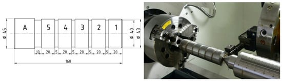
The geometry of the external cylindrical specimens was designed according to the requirements of the full factorial experimental design described later in this subsection. As shown in Figure 1, each specimen consists of several cylindrical sections. Prior to burnishing, all surfaces were finish-turned under identical conditions using a feed rate of ft1 = 0.20 mm/rev followed by ft2 = 0.15 mm/rev.
Figure 1.
The geometry and the position of the workpiece in the work area.
A low-alloy EN AW-2011 aluminum alloy with ~160 HV was selected as the workpiece material. Owing to its relatively low alloying element content, the mechanical properties of this alloy are strongly influenced by the machining process, making it particularly suitable for investigating the effects of diamond burnishing. Consequently, improvements in surface integrity and service life can be achieved through mechanical surface treatment, without the need to modify the alloy composition or apply additional heat treatment processes. Such an approach may simultaneously contribute to simplifying the manufacturing process, reducing environmental impact and expanding the industrial applicability of low-alloyed aluminum alloys. The exact chemical composition of the material was verified using an Apollo X scanning electron microscope (SEM). The averaged results of the measurements, together with the principal physical and mechanical properties of the material, are summarized in Table 1.
Table 1.
The chemical composition and physical properties of the material under examination.
During the experiments, the effects of burnishing force, feed rate and the number of passes were investigated, for which full factorial design method was selected, as it enables the determination of the optimal operating range of the investigated factors using linear or, at most, second-order mathematical models. Another important advantage of this approach is that, by varying the factors simultaneously, it allows not only the evaluation of the individual effects of each parameter but also the analysis of their interactions. Consequently, it is possible to evaluate not only the individual effects of burnishing force, feed rate and number of passes, but also the interaction effects between these process parameters. Furthermore, the required number of experiments can be maintained within reasonable limits, making the method well suited for industrial applications as well.
The burnishing process parameter levels are summarized in Table 2. It was established based on a comprehensive review of the relevant literature and the results of preliminary experiments while taking into account the characteristics of the investigated material. Particular attention was paid to including extremely low feed rates, as this parameter range has received only limited attention in previous studies. Accordingly, one of the objectives of the investigation was to determine whether reducing the feed rate to this range is justified from both technological and surface quality perspectives and to evaluate the influence of fine-machining parameter settings on the resulting surface integrity.
Table 2.
The transformed and numerical burnishing parameters.
Several methods can be employed to evaluate experimental results, including response surface methodology, in which the regression function obtained by the least squares method is represented in three-dimensional space. This approach not only enables the determination of the optimum within the investigated experimental domain but also facilitates the identification of promising optimization directions beyond the investigated parameter space [26,27]. In this study, the dependent variables (y) are expressed as dimensionless ratios representing the percentage changes induced by the diamond burnishing process. These ratios also consider the initial surface condition prior to burnishing, denoted by , according to Equation (1), where represents the corresponding surface characteristic after burnishing.
where:
- —Residual stress parameter remaining after turning,
- —Residual stress parameter remaining after burnishing,
- —Percentage value of the improvement ratio.
Since the objective is to maximize the analyzed response characteristic, the optimum process condition corresponds to the highest value of .
Although the percentage-based indicator effectively reflects the relative improvement induced by the burnishing process, its magnitude is strongly influenced by the initially low residual stress level. Therefore, absolute residual stress values expressed in MPa should be regarded as the primary basis for engineering interpretation, while the percentage indicator should be used mainly for comparative purposes.
2.2. The Modelling Phase
Numerical modelling has long served as an effective tool for the investigation and design of metal forming processes, as it enables detailed analysis of material deformation and internal stress evolution, thereby accelerating and improving the reliability of process design [28,29,30]. Consequently, numerical simulation techniques have become indispensable in engineering and scientific research, allowing complex physical phenomena to be investigated and engineering decisions to be supported without relying exclusively on costly and time-consuming experimental studies. Furthermore, the finite element method (FEM) provides detailed information on the local distribution of surface deformation, which is often difficult or expensive to obtain experimentally.
One of the objectives of the present study was to develop a finite element model of diamond burnishing process for external cylindrical workpieces that enables efficient parametric investigations of both technological and theoretical problems related to the state of the residual stress of the material while eliminating the need for destructive testing. For this purpose, to investigate the process numerically, a two-dimensional computational model was developed in DEFORM 13.1.1. Compared with a three-dimensional model, the 2D approach offers significantly lower computational cost and shorter simulation time while allowing straightforward modification of the model geometry. Although based on a planar representation of the cylindrical geometry, the developed model is suitable for predicting the axial residual stress distribution.
When constructing the geometrical model, based on the relative motion between the tool and the workpiece, the process was simplified into two interacting bodies: the workpiece surface and the spherical polycrystalline diamond (PCD) burnishing tip. Consequently, the model consists of an upper tool and a deformable workpiece. Owing to the significantly higher stiffness and hardness of the PCD tool material compared to the investigated aluminum alloy, elastic and plastic deformation of the tool was considered negligible. Consequently, the tool was modelled as a rigid body with a constant cross-section throughout the simulation, and mesh generation was required only for the workpiece, which substantially reduced the computational effort.
The initial workpiece surface was generated using the control-point definition capability available in DEFORM software 13.1.1. The measured surface profile was imported from Altimap software, associated with the AltiSurf® 520 surface topography measuring equipment, over an evaluation length of 4 mm. Accordingly, the pre-burnished (turned) surface topography was reconstructed from 4000 measured surface points representing the deviations in the y-direction.
Previous theoretical investigations, experimental results and published studies have consistently shown that the influence of the burnishing process is generally confined to a subsurface depth of approximately 0.02–0.17 mm. Therefore, to reduce computational time, an additional simplification was introduced by limiting the thickness of the workpiece model to 0.20 mm.
Another important challenge in constructing a realistic FE model was the generation of an appropriate mesh. The simulation was initially performed using a relatively coarse mesh with a limited number of elements to facilitate a mesh convergence study. The mesh density was progressively refined (first globally and then locally within the critical contact region) until further refinement resulted in only marginal changes in the predicted residual stress field while substantially increasing computational time. The final mesh was therefore selected as a compromise between numerical accuracy and computational efficiency. Since plastic deformation is concentrated within the subsurface layer, a denser mesh was applied within the first 0.02 mm below the surface to ensure accurate representation of the mechanical behavior in the contact zone. The final mesh consisted of approximately 12,500 finite elements and 13,100 nodes, with element sizes ranging from approximately 0.003 mm to 0.021 mm.
Accurate finite element discretization also requires an appropriate constitutive material model capable of realistically representing the mechanical behavior of the investigated material. The material model mathematically describes the response of the material to external loading and determines the conditions under which the material transitions from elastic to plastic deformation. To obtain reliable predictions of the residual stress distribution, a combined isotropic–kinematic hardening model was adopted, as this constitutive formulation accurately captures the complex hardening mechanisms occurring during elastic–plastic deformation. To improve the realism of the numerical model, the true stress–strain curve of the investigated EN AW-2011 aluminum alloy was determined experimentally using Watts–Ford test. DEFORM software provides direct support for importing experimentally measured flow curves and converting them into the internal material database while accounting for the adiabatic correction of the experimental data. Consequently, a realistic, application-oriented material model was established using the experimentally determined flow curve. By fitting the experimental data to the built-in power-law constitutive equation available in DEFORM, the strain-dependent flow stress can be expressed as follows:
where:
- —Material constant—c = 190.454,
- —Effective plastic strain,
- —Effective strain rate,
- —Strain component—n = 0.10571,
- —Strain rate exponent—m = 1.02487,
- —Initial value—y = 87.194 MPa
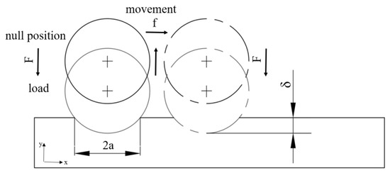
DEFORM 13.1.1 software also allows the tool motion to be prescribed in two-dimensional simulations either as a time-dependent function or as a function of the tool profile and feed parameters. To analyze the residual stress distribution, a cyclic tool motion consisting of four successive steps was implemented, as illustrated schematically in Figure 2 (shown with exaggerated dimensions for clarity):
Figure 2.
Simulation of the movement of the burnishing tool.
- Starting from the predefined reference position, the tool penetrates the workpiece in the negative y-direction to a depth of δ, while the prescribed burnishing force is applied as the control parameter.
- The tool returns to its initial reference position.
- The tool is translated in the positive x-direction by the prescribed feed distance.
- The cycle is repeated and the tool again moves in the negative y-direction while applying the prescribed burnishing force.
This cyclic simulation strategy has been successfully adopted in several previous studies [31,32,33]. In the present work, the loading cycle was repeated ten times. Due to the application of minimum quantity lubrication during the burnishing process, frictional effects were assumed to be negligible in the present model.
2.3. The Measuring Phase
Several well-established techniques are available for residual stress measurement. Destructive methods include hole-drilling, sectioning and other techniques based on mechanical material removal. Alternatively, residual stress can be evaluated using non-destructive methods, such as Magnetic Barkhausen Noise (MBN) analysis, ultrasonic testing, neutron diffraction or X-ray diffraction (XRD), which was selected in the present study. The XRD technique utilizes the wave nature of X-rays to determine the internal stress state of crystalline materials [34].
To improve the reliability and comparability of the measurement results, a uniform measurement protocol was applied throughout the entire experiment. The use of a regularly calibrated X-ray diffractometer, standardized measurement conditions and identical data evaluation procedures contributed to the consistency of the obtained residual stress values and supported the traceability of the measurement process [35].
Residual stress measurements were performed in accordance with the requirements of the MSZ EN 21432:2019 standard [36] using a Stresstech Xstress 3000 G3R X-ray diffractometer. Instrument control, data acquisition and data processing were carried out using the manufacturer’s XTronic software package. In all cases, measurements were performed both before and after the diamond burnishing process to enable a direct comparison of the resulting residual stress state.
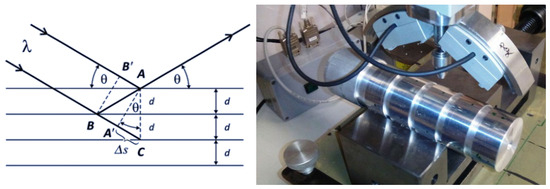
At the microscopic level, macroscopic residual stresses cause a displacement of atoms from their equilibrium positions within the crystal lattice, resulting in a change in the lattice parameters. Since the spacing between crystallographic lattice planes is altered by the presence of residual lattice strains, the measurement of these interplanar spacings provides the basis for calculating the corresponding residual stresses. In the applied X-ray diffraction method, the wavelength of the incident X-rays is known, and the shift of the Bragg diffraction angle resulting from the change in the interplanar spacing, (dhkl), is measured. The applied method relies on Bragg’s law, which establishes the relationship between the diffraction angle and the interplanar spacing of crystallographic planes characterized by a given Miller index [37]:
where:
- —Integer determined by order given;
- —Wavelength of X-ray;
- dhkl—Spacing between the planes in the atomic lattice;
- —Angle between the incident ray and the scattering planes.
Residual stress measurements were performed using the sin2ψ method with Cr-Kα radiation (λ = 2.291 Å) and the Al (311) crystallographic reflection. During the measurements, the specimen remained stationary while the X-ray tube and detector system were tilted relative to the specimen surface. Residual stresses were determined in both the axial and tangential directions to evaluate the anisotropy of the stress field generated by burnishing. For each investigated surface, measurements were performed at four locations distributed uniformly around the circumference of the cylindrical specimen with an angular spacing of 90°. Depending on the investigated location, diffraction patterns were acquired at 5–9 ψ positions using a beam diameter of 1–3 mm. Residual stress values were subsequently calculated using the XTronic software package supplied with the instrument.
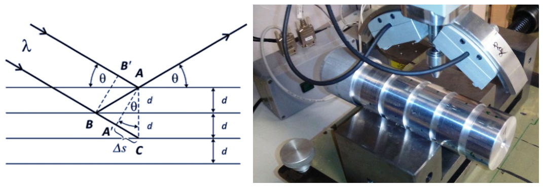
The fundamental principle of the X-ray diffraction technique (left) and the measurement configuration employed in the present study (right) are illustrated in Figure 3.
Figure 3.
The theoretical basis (left) [38] and implementation (right) of the X-ray diffraction method.
Although X-ray diffraction is a well-established technique for residual stress measurement, its application for aluminum alloys presents several material-specific challenges. Therefore, particular attention was paid to the reliability and evaluation of the acquired diffraction data.
3. Results
This section presents the experimental and numerical results obtained during the investigation of the burnishing process. Residual stress values determined by X-ray diffraction are reported first, followed by the corresponding finite element simulation results.
3.1. The Experimental Results
Table 3 and Table 4 summarize the average residual stresses measured in the tangential and axial directions for each workpiece section, together with their corresponding average uncertainty estimates and the dimensionless ratios calculated from the experimental results. The reported residual stress values represent the average of four measurements performed at equally spaced circumferential locations around each cylindrical surface section. In addition to the measured stress values, the X-ray diffraction system provided stress uncertainty estimates (±) associated with the residual stress determination procedure. These values reflect the uncertainty of the calculated stress state originating from the diffraction data evaluation and were considered during the interpretation of the experimental results.
Table 3.
The measured values, standard deviations and the calculated improvement ratios for δt.
Table 4.
The measured values, standard deviations and the calculated improvement ratios for δa.
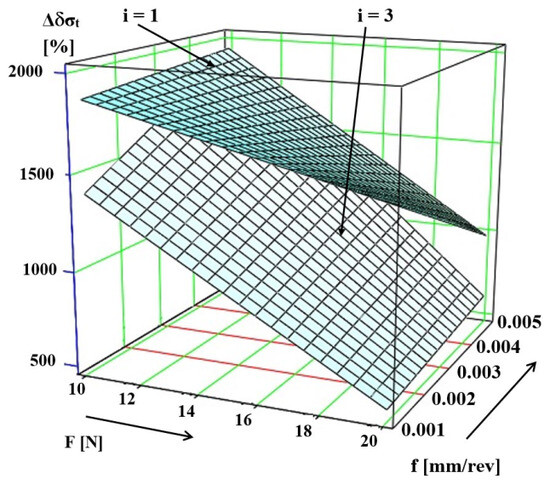
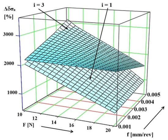
Based on the full factorial experimental design method, regression models were fitted to the measured response variables by considering the contributions of both the main effects and their interaction effects. The resulting regression equations are presented in Equations (4) and (5), whereas the corresponding response surfaces were constructed and visualized using Mathcad software (Prime 10), as shown in Figure 4 and Figure 5.
Figure 4.
The response surface for the change in δt in factor space.
Figure 5.
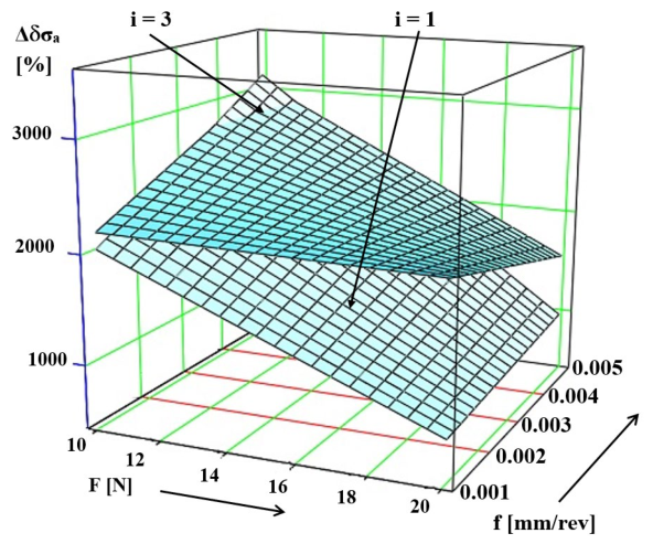
The response surface for the change in δa in factor space.
For the residual stresses measured in the tangential direction, a favorable compressive stress state was observed at all measurement locations within the subsurface layer as a result of diamond burnishing process. The results indicate that the burnishing force (F) and feed rate (f) exert a direct influence on the evolution of residual stress. In contrast, the number of passes (i) exhibits a less pronounced individual effect; however, its interaction with the feed rate appears to influence the resulting stress state.
Based on the measured residual stresses in the axial direction, it can be observed that the combined effect of the burnishing force and the feed rate also plays a key role in determining the residual stress state. The response surface exhibits a slightly curved yet relatively smooth profile, indicating that the effects of the process parameters are manifested in a gradual and predictable manner, allowing the observed behavior to be represented by the developed regression model.
3.2. The Numerical Results
The objective of the finite element simulation was to predict and analyze the residual stress state generated during the diamond burnishing process, as well as to investigate the correlation between the numerical predictions and the experimental results. The adopted two-dimensional model, which approximates the cylindrical geometry using a planar representation, is suitable for estimating the axial residual stress distribution. Table 5 summarizes the residual stress values obtained from the numerical simulations and compares them with the corresponding experimentally measured values, including the average standard deviations that reflect the measurement uncertainty associated with the X-ray diffraction technique.
Table 5.
Simulated and experimental results for axial residual stress.
The average absolute deviation between the experimental and simulated residual stress values was 155.2 MPa, whereas the average uncertainty associated with the X-ray diffraction measurements was 61.8 MPa. Although the numerical model systematically predicted lower compressive residual stress values, it reproduced the overall trends observed in the experimental results. Despite the systematic differences in absolute stress values, a semi-quantitative agreement was observed between the numerical predictions and the experimental measurements with respect to the trends induced by the investigated burnishing parameters. Accordingly, the developed finite element model can be considered suitable for trend prediction and subsurface residual stress analysis.
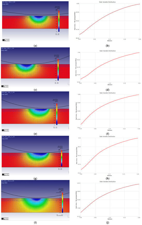
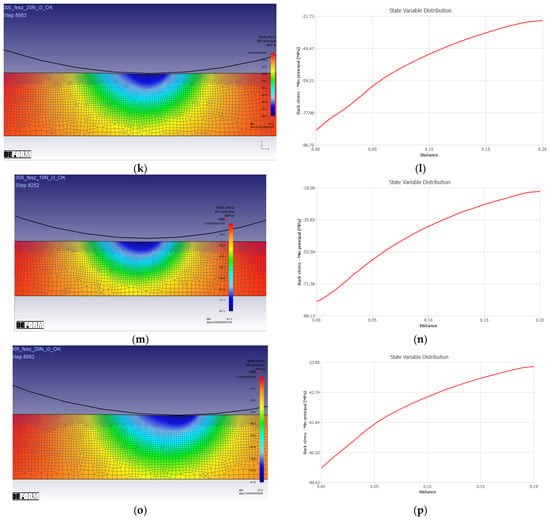
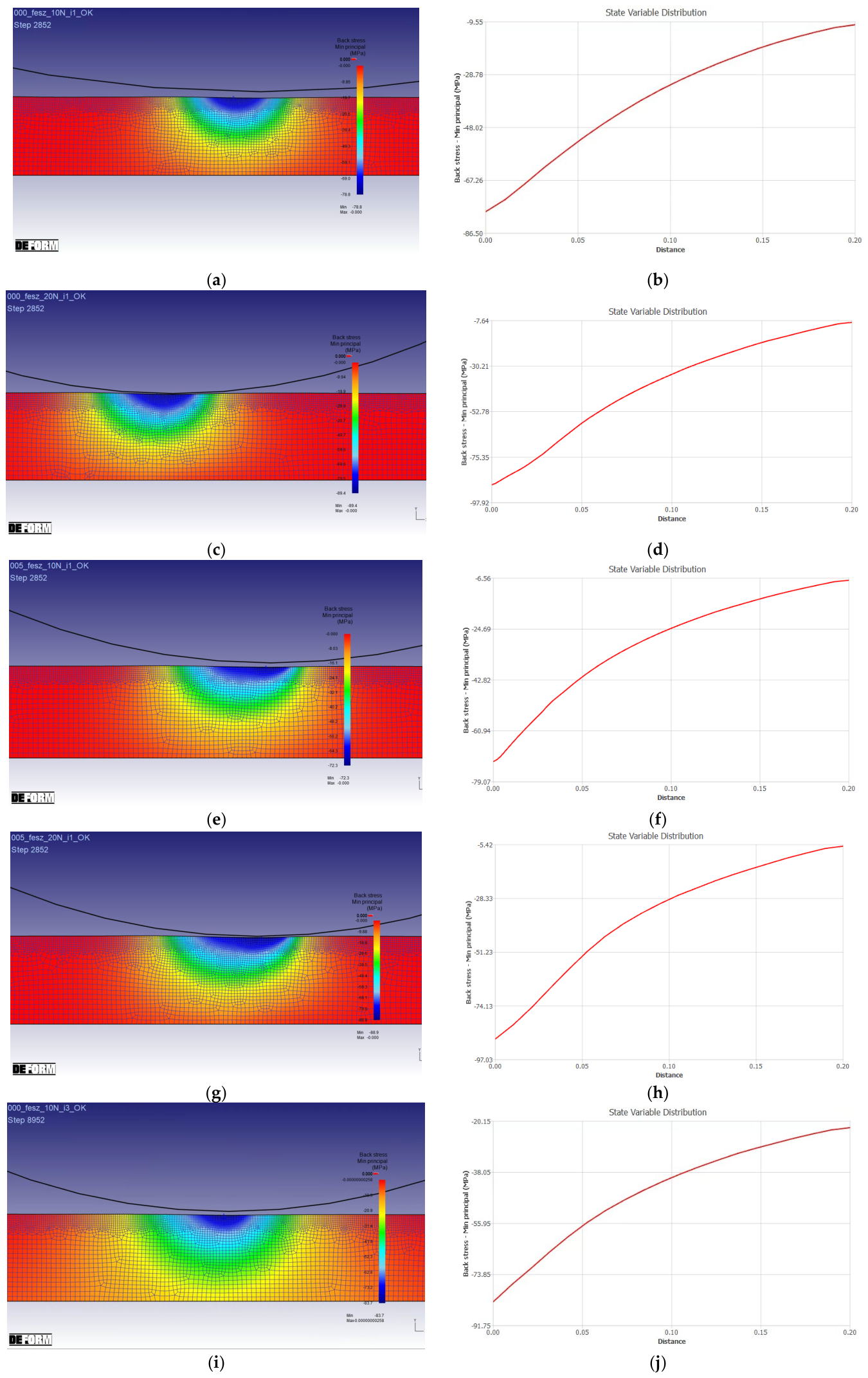
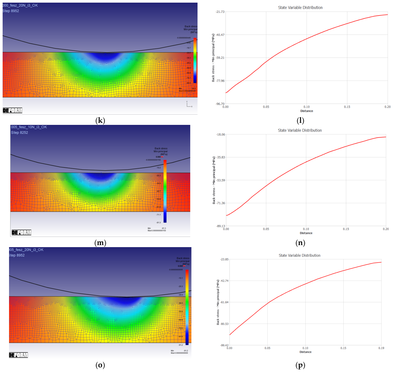
The following Figure 6 presents the residual stress distributions obtained from the developed finite element model. For each investigated case, the stress distributions are also illustrated as a function of depth below the burnished surface.
Figure 6.
Residual stress fields obtained from the finite element model for surface Nos. 1–8. Panels (a,c,e,g,i,k,m,o) present the simulated stress distribution in the vicinity of the burnished surface, while panels (b,d,f,h,j,l,n,p) show the corresponding residual stress depth distribution.
The contour maps presented in Figure 6a,c,e,g,i,k,m,o illustrate the residual stress distribution based on the minimum principal stress values, with the corresponding compressive stress levels expressed in MPa. The dark blue regions represent the highest compressive stresses, which are concentrated directly beneath the contact zone between the burnishing tool and the workpiece surface. This plastically deformed subsurface layer extends to a considerable depth according to the simulation results, owing to the favorable formability of the aluminum alloy. Although previous studies have primarily focused on surface strengthening and subsurface residual stress modification, the present results suggest that, in the case of EN AW-2011, compressive residual stresses persist well below the immediate surface layer.
All investigated burnishing parameter combinations resulted in a balanced deformation state. Consequently, high-intensity stress changes were generated in the subsurface region, whereas lower but still measurable residual stress levels remained in the deeper layers. The depth profiles shown in Figure 6b,d,f,h,j,l,n,p quantitatively confirm this tendency. The maximum compressive stresses occur within the first 0–0.05 mm beneath the surface, followed by a gradual decrease with increasing depth; however, detectable compressive residual stresses remain present up to a depth of approximately 0.20 mm. Furthermore, the slope of the curves, particularly within the subsurface region, clearly reflects the intense plastic deformation occurring in the material directly affected by the burnishing tool.
4. Discussion
The residual stress values determined by X-ray diffraction are examined separately and together with the corresponding finite element predictions to identify similarities, discrepancies and underlying trends. Special emphasis is placed on the capability of the numerical model to reproduce the experimentally observed stress state and on the limitations associated with the applied measurement methodology.
4.1. Effects of Burnishing Parameters on Residual Stress
In the case of the tangential residual stresses, a beneficial change, i.e., an increase in compressive residual stress, was observed in the subsurface region at all investigated measurement points as a result of the burnishing process. The experimental results indicate that the burnishing force (F) and feed rate (f) act as the primary factors governing the evolution of residual stress. Although the independent effect of the number of passes (i) is less pronounced, a significant interaction was identified between the number of passes and the feed rate.
The response surface shown in Figure 4 clearly demonstrates that increasing the feed rate at higher number of passes may lead to a disproportionately large degree of plastic deformation. This behavior can result in substantial modification of the surface layer and a less uniform stress distribution. Such a tendency may be explained by the material response characteristic of cold plastic deformation processes, where the accumulation of permanent strain due to repeated deformation may reach a level at which further increases in compressive residual stress are no longer achieved and, in some cases, a reduction in the compressive stress level may occur.
The observed behavior may be associated with the saturation of microstructural changes induced by plastic deformation, followed by local structural rearrangements within the material. Therefore, the results suggest that achieving a favorable compressive residual stress state does not necessarily require the maximum number of passes. Instead, the optimal outcome is obtained through an appropriate balance of deformation energy, primarily governed by the combination of burnishing force and feed rate.
Residual stress measured in the axial direction also indicates that the burnishing process generates significant compressive stress within the near-surface layer of the workpiece. All Δδσa percentage values listed in Table 4 are positive, with the lowest increase exceeding 800%, while the maximum improvement reaches 3141.05%. Such values represent a substantial enhancement of the axial residual stress state compared to the turned condition.
The response surface shown in Figure 5 reveals that the combined influence of burnishing force and feed rate plays a key role in the development of axial residual stresses as well. The magnitude of the compressive stress increases progressively with increasing burnishing force, particularly at lower feed rates, where the tool interacts with the surface layer for a longer period and in a more concentrated manner. The relatively smooth and moderately curved shape of the response surface suggests that the effects of the investigated parameters are stable and can be described reliably by the developed model.
The number of passes also exhibits a noticeable influence, especially when considered in combination with burnishing force and feed rate. The displacement of the response surface in the region corresponding to “i = 3” indicates that repeated tool passes promote a greater degree of plastic deformation, resulting in a further increase in compressive residual stress. However, the overall stability of the response surface suggests that, within the investigated parameter range, increasing the number of passes did not produce signs of stress instability or excessive stress concentration.
It should be noted that tangential residual stresses primarily originate from circumferential deformation, associated with the rotational motion of the workpiece. Because the applied loading is distributed around the entire circumference, these stresses are generally more symmetric and less localized. In contrast, the more pronounced increase in axial compressive stress can be attributed to the mechanical characteristics of cylindrical surface burnishing, where material flow, plastic deformation and surface layer densification are promoted predominantly in the feed direction. This interpretation is consistent with previously reported numerical investigations of burnishing-induced surface modification and residual stress development [14,33].
4.2. Measurement Uncertainty Considerations
In addition to residual stress values, the X-ray diffraction measurements provided the associated stress uncertainties (±), diffraction peak positions (2θ) and full width at half maximum (FWHM) values. These parameters were considered during the interpretation of the measurement results, since peak broadening and signal quality may influence the reliability of residual stress determination in aluminum alloys.
A closer examination of the individual measurement results reveals a relatively wide scatter of the obtained residual stress values. At first glance, this may raise concerns regarding the reliability of the measured data; however, the observed variability primarily originates from the inherent challenges associated with X-ray diffraction measurements on aluminum alloys. Due to their low atomic number, aluminum-based materials generally exhibit lower diffraction intensities, resulting in diffraction peaks that are often weak and broadened compared to those obtained from many other engineering materials. This effect becomes particularly pronounced in cold-worked materials with a strongly textured microstructure, where preferred crystallographic orientations and locally accumulated dislocation stresses may significantly influence the diffraction response [39,40].
Consequently, the residual stress values determined by X-ray diffraction are subject to increased measurement uncertainty, highlighting an important material-specific limitation of the technique when applied to aluminum alloys. In this regard, the studies of Ungár [41] and Bereznai [42] demonstrated that diffraction peak broadening increases with decreasing grain size and increasing lattice defect density.
The relatively large standard deviations reported in Table 3 and Table 4 further support the presence of considerable measurement variability. In several cases, the associated uncertainty values represent a substantial fraction of the measured residual stress, indicating that the interpretation of the results should take the limitations of the X-ray diffraction technique into account. Therefore, the reported stress values should not be considered independently from their associated uncertainty estimates.
These considerations further justify the application of FEM simulations as a complementary tool for interpreting the experimental results. Although the numerical model is also associated with its own assumptions and uncertainties, it is not affected by the material-specific diffraction phenomena that influence the accuracy of X-ray diffraction measurements. Therefore, the finite element approach serves as an effective means for supporting the interpretation of the measured data and providing additional insight into the evolution of the residual stress state.
4.3. Comparison of Experimental and Numerical Results
The comparison of the experimental and numerical results highlights the complementary nature of the two approaches. Whereas X-ray diffraction provides direct measurements of residual stress within the near-surface layer, the finite element model enables the investigation of the complete stress field and its variation with depth.
However, due to the physical limitations of X-ray diffraction, information can only be obtained from a shallow subsurface region, typically within a penetration depth of approximately 5–10 µm [43]. Although the effective probing depth can be increased to some extent by modifying the characteristics of the incident radiation, detailed characterization of subsurface layers remains limited. An alternative approach could be neutron diffraction, which provides substantially greater penetration depth; however, its spatial resolution and sensitivity in the near-surface region are lower, making it less suitable for the detailed investigation of thin deformation-affected layers.
A comparison between the finite element simulations performed for residual stress prediction and the experimental data obtained from X-ray diffraction measurements indicates the presence of a systematic deviation between the two approaches. Nevertheless, the relative trends associated with the investigated burnishing parameters show good agreement in several cases. As summarized in Table 5, the finite element model consistently predicts lower compressive residual stress values than those measured experimentally. This discrepancy can be attributed partly to the measurement uncertainties inherent to X-ray diffraction analysis of aluminum alloys and partly to the idealized geometry and boundary conditions employed in the numerical model.
5. Conclusions
This study investigated the influence of diamond burnishing process applied to external cylindrical surfaces on the resulting residual stress state through a combination of experimental and numerical approaches. The primary objective was to improve the understanding of the physical mechanisms governing the burnishing process and to provide the foundation for the development of a finite element model supporting the industrial implementation of the technology.
To achieve a more comprehensive assessment of surface integrity, residual stresses were experimentally evaluated in both the tangential and axial directions using X-ray diffraction measurements. The application of numerical simulations further enabled the investigation of the subsurface stress distribution and its homogeneity, providing valuable information for the reliable design of fatigue-critical components. In addition, the finite element model contributed to the interpretation of the experimental results by allowing a more detailed examination of material-specific and process-related effects influencing the measured residual stress values.
Based on the conducted investigations, the following conclusions can be drawn:
- Sliding diamond burnishing generated significant compressive residual stress in both tangential and axial directions on external cylindrical surfaces. The magnitude of the resulting residual stress was influenced not only by the individual process parameters but also by their interactions. In the tangential direction, the residual stress state was governed primarily by the combined effect of the number of passes and the feed rate, highlighting the importance of their proper selection.
- The scatter observed in the X-ray diffraction measurements was strongly influenced by material-specific diffraction characteristics of aluminum alloys, including their low atomic number, pronounced crystallographic texture and dislocation-induced lattice distortions. The measured residual stress values were therefore associated with increased measurement uncertainty, as confirmed by the relatively large standard deviations and uncertainty ranges obtained during the experiment. In contrast, the finite element simulations enabled a detailed investigation of the subsurface distribution of compressive residual stresses and demonstrated a clear sensitivity to variations in the technological parameters.
- It was demonstrated that the depth distribution of axial residual stress generated by diamond burnishing can be estimated numerically using a finite element model based on the actual mechanical properties of the investigated material and simplified geometric assumptions. Comparison of the numerical predictions with the X-ray diffraction measurements showed that the model consistently predicted lower compressive residual stress values; however, it provided valuable information regarding the depth-dependent evolution of the stress field. The results confirmed that the developed finite element model is suitable for evaluating both the subsurface distribution and the homogeneity of residual stress and can therefore be applied to predict the integrity of fatigue-critical surface layers.
A promising direction for future work is the development of an analytical description of the residual stress state. Establishing a predictive relationship capable of estimating the maximum or characteristic compressive residual stress as a function of the processing parameters and material properties would complement both the experimental measurements and numerical simulations. Such an approach could introduce a third analytical pillar alongside measurement and simulation while also supporting the interpretation of measurement results affected by uncertainty and limited penetration depth.
Funding
This research received no external funding.
Data Availability Statement
The original contributions presented in the study are included in the article; further inquiries can be directed to the corresponding author.
Acknowledgments
The author fully acknowledges and greatly appreciates the support of the University of Miskolc in the preparation of this work.
Conflicts of Interest
The author declares no conflicts of interest.
References
- Kluz, R.; Bucior, M.; Dzierwa, A.; Antosz, K.; Bochnowski, W.; Ochal, K. Effect of Diamond on the Properties of FSW Joints of EN AW-2024 Aluminum Alloys. Appl. Sci. 2023, 13, 1305. [Google Scholar] [CrossRef] [Scilit]
- Cagan, S.C. Surface Quality and Environmental Impact Analysis of Ball Burnishing on Aluminum-Lithium Alloy. Materials 2025, 18, 1252. [Google Scholar] [CrossRef] [Scilit] [PubMed]
- Besliu-Bancescu, I.; Slatineanu, L. Influence of Machining Environments on the Burnishing Performance of Aluminum Alloy EN AW-2007. Lubricants 2025, 13, 368. [Google Scholar] [CrossRef] [Scilit]
- Skoczylas, A.; Zaleski, K. Selected Properties of the Surface Layer of C45 Steel Parts Subjected to Laser Cutting and Ball Burnishing. Materials 2020, 13, 3429. [Google Scholar] [CrossRef] [Scilit] [PubMed]
- Abodena, A. Optimization of Surface Roughness of Brass by Burnishing. Int. J. Eng. Inf. Technol. 2019, 5, 90–96. [Google Scholar] [CrossRef] [Scilit]
- Maximov, J.; Duncheva, G.; Anchev, A.; Dunchev, V.; Argirov, Y.; Nikolova, M. Effects of Heat Treatment and Diamond Burnishing on Fatigue Behaviour and Corrosion Resistance of AISI 304 Austenitic Stainless Steel. Appl. Sci. 2023, 13, 2570. [Google Scholar] [CrossRef] [Scilit]
- Duncheva, G.; Maximov, J.; Anchev, A.; Dunchev, V.; Argirov, Y. Improvement in Wear Resistance Performance of CuAl8Fe3 Single-Phase Aluminum Bronze via Slide Diamond Burnishing. J. Mater. Eng. Perform. 2021, 31, 2466–2478. [Google Scholar] [CrossRef] [Scilit]
- Cagan, S.C.; Tasci, U.; Pruncu, C.I.; Bostan, B. Investigation of the Effects of Eco-Friendly MQL System to Improve the Mechanical Performance of WE43 Magnesium Alloys by the Burnishing Process. J. Braz. Soc. Mech. Sci. Eng. 2023, 45, 22. [Google Scholar] [CrossRef] [Scilit]
- Somatkar, A.; Dwivedi, R.; Chinchanikar, S. Comparative Evaluation of Roller Burnishing of Al6061-T6 Alloy Under Dry and Nanofluid Minimum Quantity Lubrication Conditions. Met. Work. Mater. Sci. 2024, 26, 57–74. (In Russian) [Google Scholar] [CrossRef] [Scilit]
- Varga, G.; Smolnicki, S. The Effect of Technological Parameters on the Change in Surface Microhardness During the External Cylindircal Burnishing of X5CrNi18-10 Steel Workpieces. MM Sci. J. 2025, 8353–8358. [Google Scholar] [CrossRef] [Scilit]
- Kovacs, G.F.; Viharos, Z.J.; Kodacsy, J. Improving of Surface Tribological Properties by Magnetic Assisted Ball Burnishing. Surf. Coat. Technol. 2022, 437, 128317. [Google Scholar] [CrossRef] [Scilit]
- Kebede, F.T.; Felho, C.; Sztankovics, I. Improving Surface Roughness of 42CrMo4 Low Alloy Steel Shafts by Applying Varying Feed in the Multi-Pass Slide Burnishing Process. Appl. Sci. 2025, 15, 9063. [Google Scholar] [CrossRef] [Scilit]
- Cui, P.; Liu, Z.; Yao, X.; Cai, Y. Effect of Ball Burnishing Pressure on Surface Roughness by Low Plasticity Burnishing Inconel 718 Pre-Turned Surface. Materials 2022, 15, 8067. [Google Scholar] [CrossRef] [Scilit] [PubMed]
- Amini, C.; Jerez-Mesa, R.; Travieso-Rodriguez, J.A.; Lluma, J.; Estevez-Urra, A. Finite Element Analysis of Ball Burnishing on Ball-End Milled Surfaces Considering Their Original Topology and Residual Stress. Metals 2020, 10, 638. [Google Scholar] [CrossRef] [Scilit]
- Summers, S.; Nigh, E.; Sabeh, K.; Robinson, R. Clinical and Radiographic Outcomes of Total Hip Replacement with a 3-part Metaphyseal Osseointegrated Titanium Alloy Stem Enhanced with Low Plasticity Burnishing: A Mean 5-Year Follow-Up Study. Arthroplast. Today 2019, 5, 352–357. [Google Scholar] [CrossRef] [Scilit] [PubMed]
- Posdzich, M.; Stöckmann, R.; Morczinek, F.; Putz, M. Investigation of a Plain Ball Burnishing Process on Differently Machined Aluminium EN AW 2007 Surfaces. MATEC Web Conf. 2018, 190, 11005. [Google Scholar] [CrossRef] [Scilit]
- Uddin, M.; Rech, J.; Hall, C.; Schlafer, T. Characterisation and Analysis of Surface Integrity and Residual Stress in Laser Direct Energy Deposited 316 L Alloy Subject to Plasticity Ball Burnishing. Sci. Rep. 2025, 18, 23151. [Google Scholar] [CrossRef] [Scilit] [PubMed]
- Skoczylas, A.; Zaleski, K.; Matuszak, J.; Ciecielag, K.; Zaleski, R.; Gorgol, M. Influence of Slide Burnishing Parameters on the Surface Layer Properties of Stainless Steel and Mean Positron Lifetime. Materials 2022, 15, 8131. [Google Scholar] [CrossRef] [Scilit] [PubMed]
- Shokry, A.; Gowid, S.; Mulki, H.; Kharmanda, G. On the Prediction of the Flow Behavior of Metals and Alloys at a Wide Range of Temperatures and Strain Rates Using Johnson-Cook and Modified Johnson-Cook-Based Models: A Review. Materials 2023, 16, 1574. [Google Scholar] [CrossRef] [Scilit] [PubMed]
- Teimouri, R.; Amini, S.; Bami, A.B. Evaluation of Optimized Surface Properties and Residual Stress in Ultrasonic Assisted Ball Burnishing of AA6061-T6. Measurement 2018, 116, 129–139. [Google Scholar] [CrossRef] [Scilit]
- Savaria, V.; Bridier, F.; Bocher, P. Computational quantification and Correction of the Errors Induced by Layer Removal for Subsurface Residual Stress Measurements. Int. J. Mech. Sci. 2012, 64, 184–195. [Google Scholar] [CrossRef] [Scilit]
- Feng, B.; Lin, D.; Guo, W.; Cai, Y.; Xue, J.; Aslam, J.; Song, Q.; Wang, B.; Liu, Z. Enhanced Mechanical Properties of Ti-6Al-4V Titanium Alloy Through Laser-Assisted Burnishing. Int. J. Adv. Manuf. Technol. 2025, 137, 2635–2648. [Google Scholar] [CrossRef] [Scilit]
- Ichkova, M. Effective Surface Residual Stress in Diamond Burnishing 18/8 Austenitic Stainless Steels. Int. J. Innov. Res. Sci. Stud. 2025, 8, 1930–1940. [Google Scholar] [CrossRef] [Scilit]
- Maximov, J.; Duncheva, G.; Anchev, A.; Dunchev, V.; Argirov, Y. Effect of Diamond Burnishing on Fatigue Behaviour of AISI 304 Chromium-Nickel Austenitic Stainless Steel. Materials 2022, 15, 4768. [Google Scholar] [CrossRef] [Scilit] [PubMed]
- Korzynski, M.; Dudek, K.; Korzynska, K. Effect of Slide Diamond Burnishing on the Surface Layer of Valve Stems and the Durability of the Stem-Graphite Seal Friction Pair. Appl. Sci. 2023, 13, 6392. [Google Scholar] [CrossRef] [Scilit]
- Finszter, F.; Aradi, P.; Czmerk, A.; Németh, Z.; Wenzel, K.; Gerőfy, A.; Halmai, A. Járműipari Tesztelés és Jóváhagyás; BME MOGI: Budapest, Hungary, 2014. (In Hungarian) [Google Scholar]
- Johanyák, Z.C. Bevezetés a Kísérletmódszertanba; Kecskeméti Főiskola: Kecskemét, Hungary, 2002. (In Hungarian) [Google Scholar]
- Molnár, D. Öntvények dermedésének véges-elemes szimulációja. Fiatal Műszakiak Tudományos Ülésszaka 2003, 267–270. (In Hungarian) [Google Scholar] [CrossRef] [Scilit]
- Gál, V. A mérethatás végeselemes vizsgálata az alakítási határgörbék felvételénél. Acta Mater. Transylvanica 2020, 3, 65–69. (In Hungarian) [Google Scholar] [CrossRef] [Scilit]
- Swamy, S.; Usha, P.; Meheta, A.; Al-Fatlawi, M.; Thethi, H.P.; Pratap, B.; Bandhu, D. A review of numerical simulation and modelling in high strain rate deformation processes. E3S Web Conf. 2024, 505, 3005. [Google Scholar] [CrossRef] [Scilit]
- Stalin John, M.R.; Welsoon, A.; Wilson, A.; Prasad Bhardwaj, A.; Abraham, A.; Vinayagam, B.K. An investigation of ball burnishing process on CNC lathe using finite element analysis. Simul. Model. Pract. Theory 2016, 62, 88–101. [Google Scholar] [CrossRef] [Scilit]
- Felho, C.; Varga, G. CAD and FEM modelling of theoretical roughness in diamond burnishing. Int. J. Precis. Eng. Manuf. 2022, 23, 375–384. [Google Scholar] [CrossRef] [Scilit]
- Stöckmann, R.; Putz, M. Modelling of surface formation mechanism during burnishing of aluminium. Procedia CIRP 2019, 82, 450–454. [Google Scholar] [CrossRef] [Scilit]
- Lee, D.W.; Cho, S.S. Comparison of X-Ray residual stress measurements of rolled steels. Int. J. Precis. Eng. Manuf. 2011, 12, 1001–1008. [Google Scholar] [CrossRef] [Scilit]
- JCGM 200:201; International Vocabulary of Metrology—Basic and General Concepts and Associated Terms (VIM), 3rd Edition. Joint Committee for Guides in Metrology: Paris, France, 2012.
- MSZ EN 21432:2019; Roncsolásmentes Vizsgálatok: A maradó Feszültség Elemzésének Röntgensugaras Diffrakciós Vizsgálati Módszere [Non-Destructive Testing: Test Method for Residual Stress Analysis by X-Ray Diffraction]. Magyar Szabványügyi Testület (MSZT): Budapest, Hungary, 2019.
- Zirigh, N.; Mertinger, V.; Benke, M.; Cseh, D. Maradó feszültség mérése sínfej felületén röntgendiffrakciós módszerrel. Anyagmérnöki Tudományok 2013, 38, 359–369. (In Hungarian) [Google Scholar]
- Prohászka, J. Bevezetés az Anyagtudományba; Nemzeti Tankönyvkiadó: Budapest, Hungary, 1997; ISBN 963-19-3910-3. (In Hungarian) [Google Scholar]
- Dhara, S.; Hughes, D.J.; Huband, S.; Taylor, S.; Hazra, S. An X-ray diffraction study of the influence of linear and changing strain paths on strain and texture evolution in AA6111-T4 aluminium alloy sheets. Materialia 2024, 38, 102305. [Google Scholar] [CrossRef] [Scilit]
- Kucerakova, M.; Vratislav, S.; Kalvoda, L.; Capek, J.; Dragounova, K.; Cech, J. Neutron and X-Ray diffraction texture analysis of novel Al-Si-Mg alloy. IOP Conf. Ser. Mater. Sci. Eng. 2018, 375, 12038. [Google Scholar] [CrossRef] [Scilit]
- Ungár, T. Microstructural parameters from X-ray diffraction peak broadening. Scr. Mater. 2004, 54, 777–781. [Google Scholar] [CrossRef] [Scilit]
- Bereznai, M. Vékonyrétegek Építése Nitrogen és Argon Háttérgázban Molibdén, Volfrám, Szén és Bór-Karbid Céltárgyak Impulzuslézeres Ablációjával. Ph.D. Dissertation, University of Szeged, Szeged, Hungary, 2011. [Google Scholar]
- Meisner, L.L.; Lotkov, A.I.; Ostapenko, M.G.; Gudimova, E.Y. X-ray diffraction study of residual elastic stress and microstructure of near-surface layers in nickel-titanium alloy irradiated with low-energy high-current electron beams. Appl. Surf. Sci. 2013, 280, 398–404. [Google Scholar] [CrossRef] [Scilit]

Disclaimer/Publisher’s Note: The statements, opinions and data contained in all publications are solely those of the individual author(s) and contributor(s) and not of MDPI and/or the editor(s). MDPI and/or the editor(s) disclaim responsibility for any injury to people or property resulting from any ideas, methods, instructions or products referred to in the content. |
© 2026 by the author. Licensee MDPI, Basel, Switzerland. This article is an open access article distributed under the terms and conditions of the Creative Commons Attribution (CC BY) license.