


Abstract
Accurate determination of a vehicle’s centre of gravity (CoG) is fundamental to driving dynamics, safety, and engineering design. However, existing static CoG estimation methods often neglect tyre deflection and detailed wheel geometry, which can introduce significant errors, particularly in electric vehicles, where the low and concentrated mass of the battery pack increases the sensitivity of vertical CoG calculations. This study presents a refined static axle-load-based method for electric vehicles, in which the influence of tyre deformation and lifting height on the accuracy of the vertical centre of gravity coordinate is explicitly considered and quantitatively justified. To minimise human error and accelerate the evaluation process, a custom-developed Python (Python 3.13.2.) software tool automates all calculations, provides an intuitive graphical interface, and generates visual representations of the resulting CoG position. The methodology was validated on a Volkswagen e-Golf, demonstrating that the proposed approach provides reliable and repeatable results. Due to its accuracy, reduced measurement complexity, and minimal equipment requirements, the method is suitable for design, educational, and diagnostic applications. Moreover, it enables faster and more precise preparation of vehicle dynamics tests, such as rollover assessments, by ensuring that sensor placement does not interfere with vehicle behaviour.
1. Introduction
Determining the centre of gravity (CoG) of a vehicle is a fundamental requirement in vehicle dynamics, influencing stability, handling, rollover resistance, and the effectiveness of advanced driver assistance systems. Inaccurate CoG data can distort measurements during testing procedures, lead to incorrect interpretation of vehicle behaviour, and ultimately affect safety-critical design decisions. Precise CoG localisation is therefore essential not only in development environments but also in general automotive engineering and homologation contexts.
Although numerous methods have been proposed for CoG estimation, most existing approaches involve complex calculations, manual data processing, or measurement configurations that are difficult to perform consistently in workshop environments. Several studies highlight that static CoG estimation methods frequently neglect tyre deflection and wheel geometry, which can introduce significant errors, particularly when calculating the vertical coordinate. Furthermore, available procedures typically lack integrated software tools to support fast, error-free computation, which increases the likelihood of data entry mistakes and reduces measurement repeatability.
For vehicles equipped with internal combustion engines, fuel mass variation introduces an additional challenge, since the quantity and position of fuel continuously change, resulting in a dynamically shifting CoG. Although fully electric vehicles theoretically simplify the estimation process due to their fixed and centrally located battery packs, recent literature shows that for EVs, there is still no consensus on the lifting height required for reliable static measurements [1,2,3]. In particular, the vertical CoG coordinate is highly sensitive to small load changes, making the choice of lifting height a critical factor. At the same time, excessively high lifting can pose safety risks, especially for vehicles without dedicated lifting points.
The review of related work reveals three main research gaps:
- There is no unified or standardised procedure for static axle-load-based CoG determination, especially regarding how tyre deflection, wheel geometry, and lifting height should be considered.
- For electric vehicles, the optimal and safe lifting height remains unclear, despite their weight distribution being especially favourable for static methods.
- Existing methods lack software support that could automate the calculations, reduce human errors, and accelerate the measurement workflow.
To address these gaps, this study presents a static axle-load-based centre of gravity determination procedure specifically optimised for electric vehicles. Unlike existing standardised procedures, the proposed approach does not merely apply a conventional static method but provides a vehicle-specific refinement by explicitly considering and quantitatively assessing the influence of tyre deformation, and validating the adequacy of the selected lifting height, on the reliability of the vertical CoG coordinate. The method integrates tyre-corrected wheel geometry and a quantitatively justified lifting height to ensure both measurement safety and sufficient sensitivity of axle-load redistribution. To support reproducibility and reduce human error, the methodology is complemented by a custom-developed Python software (Python 3.13.2.) tool that automates the calculations and provides immediate visualisation of the resulting CoG position.
2. Methods for Determining the Centre of Gravity
The centre of gravity (CoG) of a vehicle can be determined using several methodological approaches, which can be grouped into four main categories: static, analytical, dynamic, and simulation-based methods. Static approaches rely on direct measurements on a stationary vehicle, analytical methods use the mass and geometric data of individual components, dynamic methods estimate the CoG from the vehicle’s response during motion, and simulation-based approaches apply model-based calculations. A concise overview of these four method families is provided below.
2.1. Static Method
Static methods determine the CoG while the vehicle is stationary, requiring only simple measurement equipment and no advanced sensor systems. Two common approaches are the axle-load method and the tilt table method [4,5,6].
2.1.1. Determining the Centre of Gravity Using Axle Loads
The axle-load method is among the simplest static techniques. It relies on measuring the load on the front and rear axles and calculating the longitudinal and lateral CoG position from the wheelbase, track width, and load distribution. The vertical CoG coordinate can also be obtained by lifting one end of the vehicle to a known height and performing a second axle-load measurement. The method is quick and equipment-efficient, but it is sensitive to measurement setup, scale placement, and any loose masses within the vehicle [2,3,4,5,7,8].
2.1.2. Tilt Table Method
In the tilt table method, the vehicle is placed on a tiltable platform, which is gradually inclined until the vehicle reaches the critical tilt point. The corresponding angle is then used to calculate the vertical CoG position based on the known track width. While useful for assessing rollover tendencies, this method requires substantial mechanical infrastructure and can be highly sensitive to asymmetric mass distribution [4,5,6,9,10,11].
2.2. Analytical Method
The analytical, or component-based, method is a detailed and precise approach for determining a vehicle’s centre of gravity, taking into account the mass and geometric location of every individual component. This approach is particularly useful during the design phase, when the vehicle does not yet physically exist, or when physical measurements are difficult to perform [4,5,6,12].
2.3. Dynamic Method
Dynamic methods estimate the CoG from the vehicle’s behaviour during motion, using measurements collected from IMUs, GPS, wheel-speed sensors, and similar devices. These methods capture real operating conditions, but they require complex signal processing and are sensitive to sensor noise and environmental disturbances [4,5,6,13,14,15].
2.4. Simulation-Based Method
Simulation-based methods use computer models and known mass and geometry data of vehicle components to estimate the CoG. They provide a fast and cost-effective way to evaluate different configurations, especially in the early design stages. However, their accuracy strongly depends on the reliability and completeness of input data, and not all dynamic effects can be fully represented [16,17].
Overall, the introduced methods each offer valuable insights but also exhibit notable limitations. Static approaches are simple and require minimal equipment, yet their accuracy is influenced by measurement conditions, tyre deformation, and vehicle geometry. Analytical and simulation-based methods can provide highly precise estimates, although they rely on detailed component-level mass data that are often unavailable in practical scenarios. Dynamic methods capture the vehicle’s behaviour under real operating conditions, but they demand complex instrumentation and are sensitive to sensor noise. Considering these constraints, the static axle-load method emerges as the most appropriate choice for the present research, particularly due to the stable and well-defined mass distribution of electric vehicles with fixed battery packs. Moreover, this method allows for the integration of EV-specific corrections, such as tyre deflection and wheel geometry, thereby enabling a more accurate determination of the vertical centre of gravity.
3. Materials and Methods
This study applies the static axle-load method to determine the three-dimensional centre of gravity (CoG) of an electric vehicle. The method involves three main steps: (1) measuring axle loads on a level surface; (2) repeating the measurement after lifting the vehicle by a predefined height; and (3) computing the longitudinal, lateral, and vertical CoG coordinates from load redistribution and tyre-corrected wheel geometry. While the fundamental principle follows the classical axle-load approach, the method is refined by explicitly accounting for tyre deformation and by selecting a lifting height that ensures both measurement safety and sufficient sensitivity for accurate determination of the vertical CoG coordinate in electric vehicles. This approach was selected because it requires only easily measurable quantities (axle loads, wheelbase, and track width) and avoids the complexity of dynamic or analytical component-based procedures. Its simplicity, reproducibility, and minimal equipment requirements make it particularly suitable for electric vehicles, whose fixed battery mass ensures a stable and well-defined weight distribution.
3.1. Measurement Device Used
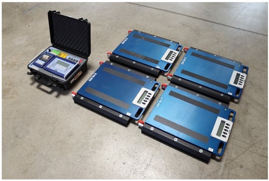
The measurements were carried out using a four-platform vehicle weighing system (Figure 1), consisting of precision scales placed under each wheel. This setup provides total vehicle mass as well as individual wheel loads with sufficient accuracy for CoG determination.
Figure 1.
The vehicle scale platform used during the investigation.
The parameters of the investigated vehicle relevant to the measurements are summarized in the table below (Table 1). The location and mass of the battery pack were not considered separately, as it is rigidly fixed within the chassis. Unlike liquid fuel in conventional vehicles, it does not redistribute during static measurements, and its weight is fully reflected in the measured axle loads. Therefore, it does not independently affect the determination of the vertical position of the centre of gravity.
Table 1.
The parameters of the investigated vehicle relative to the measurements.
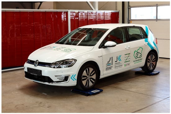
After the vehicle was correctly positioned on the scales (Figure 2), the loads on each wheel were measured. From these measurements, the axle loads and the total vehicle mass, as summarized in Table 1, were obtained. The scale platforms were placed on a level surface to ensure proper load distribution. Minor lateral offsets between the wheel contact point and the centre of the scale do not affect the measured vertical forces and therefore do not influence the accuracy of the axle-load-based CoG determination.
Figure 2.
Examination of the vehicle’s weight distribution using the scale platform.
3.2. Determination of the Centre of Gravity
3.2.1. Longitudinal Position
The longitudinal CoG coordinate is derived from the axle-load distribution. A higher rear axle load indicates that the CoG is located closer to the rear axle. The relationship is expressed as follows:
where
- Sh = longitudinal CoG position [mm];
- Gh = rear axle load [kg];
- G = total vehicle mass [kg];
- l = wheelbase [mm].
This equation provides a direct estimation of the longitudinal CoG position based on static load distribution, assuming level-ground equilibrium conditions.
3.2.2. Lateral Position
The lateral CoG coordinate is calculated from the left–right load distribution:
where
- Sk = lateral CoG position [mm];
- Gright = load on the right side [kg];
- G = total vehicle mass [kg];
- b = track width [mm].
The right side was used as the reference; therefore, Sk was measured from the right-hand wheel.
3.2.3. Vertical Position
The vertical CoG coordinate cannot be measured directly; instead, it is inferred from the change in rear axle load when the front axle is lifted by a known height. Elevating one end of the vehicle redistributes the load in proportion to the vertical distance between the CoG and the rotation axis at the opposite axle. The relationship is given by
where
- Sm = vertical CoG position [mm];
- Gh2 = rear axle load in lifted position [kg];
- l = wheelbase [mm];
- G = total vehicle mass [kg];
- Sh = longitudinal CoG coordinate [mm];
- ctg α = cotangent of the lifting angle [°];
- R = Static rolling radius [cm].
Equation (3) is derived from the static moment equilibrium of the vehicle during lifting, linking the measured load increase to the CoG height.
Since the wheel load changes depend on the static rolling radius, tyre deformation must be included to ensure accurate vertical CoG estimation.
Tyre Deformation and Wheel Geometry
Accurate calculation requires consideration of tyre deformation, incorporated via the static rolling radius:
where r is the rim radius, and Am is the tyre sidewall height.
R = r + Am
For example, in the case of a 185/65 R14 tyre:
A tyre deflection factor of 5% was adopted as a representative value based on engineering judgement and practical experience for the investigated tyre and inflation conditions. During the lifting procedure, a limited redistribution of axle loads occurs, which may slightly influence the vertical load acting on the tyres. However, as the resulting load variation is relatively small, the associated change in tyre deformation was considered negligible within the accuracy of the static measurement. The influence of this assumption is later assessed by repeating the calculation without tyre deformation, demonstrating its effect on the vertical CoG coordinate.
Lifting Height and Angle
The lifting angle α is required for Equation (3), as it defines the geometric relationship between the lifted position and the CoG height.
where
- em = lifting height [mm];
- l = the wheelbase [mm].
A lifting height of 14 cm was selected based on preliminary trials, as it produced a sufficiently large axle-load change for stable computation, remained within safe structural limits, and avoided excessive structural stress associated with higher lifting heights. The objective was not to determine an optimal lifting height, but to identify a practical and safe value that ensures reliable determination of the vertical CoG coordinate. While this lifting height was chosen for the investigated vehicle, it can generally be considered safe and practical for lifting an average vehicle without causing damage, though adjustments may be necessary for vehicles with significantly different geometries or load distributions.
3.2.4. Measurement Reliability
To minimise uncertainty, all axle-load measurements (normal and lifted) were repeated several times, and the averaged values were used. The repeated measurements showed only negligible variations under the applied test conditions. As a result, standard deviation values are not reported, and representative averaged values are presented. The following inputs were applied in the final calculations:
- Total mass;
- Front and rear axle loads (normal position);
- Rear axle load (lifted position);
- Wheelbase and track width;
- Tyre-deflection-corrected wheel radius.
Using these data, Sh and Sk were determined from Equations (1) and (2), and Sm from Equation (3). This procedure constitutes the complete static axle-load-based method used in the present study.
In summary, while all four method families provide valuable insights, the static axle-load approach offers the most suitable balance of simplicity, reproducibility, and EV-specific accuracy, which is why it was selected for the present research.
4. Results and Discussion
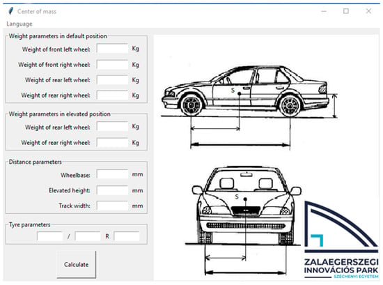
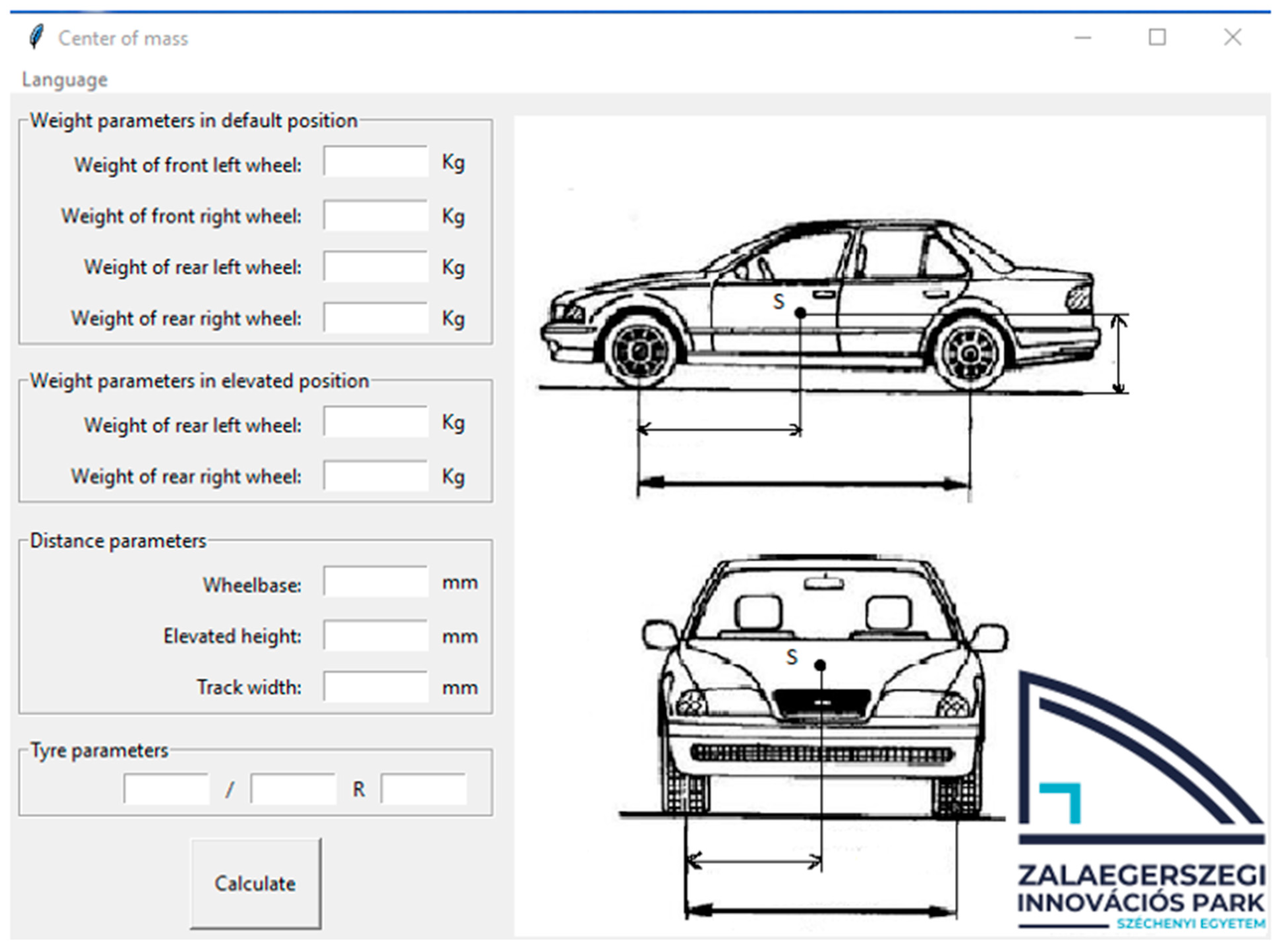
Based on the above, it can be stated that the three-dimensional (x, y, z) determination of the centre of gravity is a complex and time-consuming process in which the possibility of errors cannot be neglected. During manual calculations, rounding discrepancies and data entry errors may occur frequently. To eliminate these issues, a digital solution was developed to simplify the calculation process and to visually represent the spatial position of the vehicle’s centre of gravity (Figure 3). On the left side of the program, users can input data, including measurements obtained from the catalogue and during the process. The right side features the display interface, which visualizes the spatial positions of the centre of gravity coordinates.
Figure 3.
Custom-developed software for centre of gravity determination.
The method ensures particularly accurate results for electric vehicles, as the mass and position of the battery pack remain fixed. In the case of conventional vehicles with internal combustion engines, where the fuel quantity continuously changes, the calculation provides an estimated value that nevertheless serves as a reliable reference for determining the vehicle’s centre of gravity.
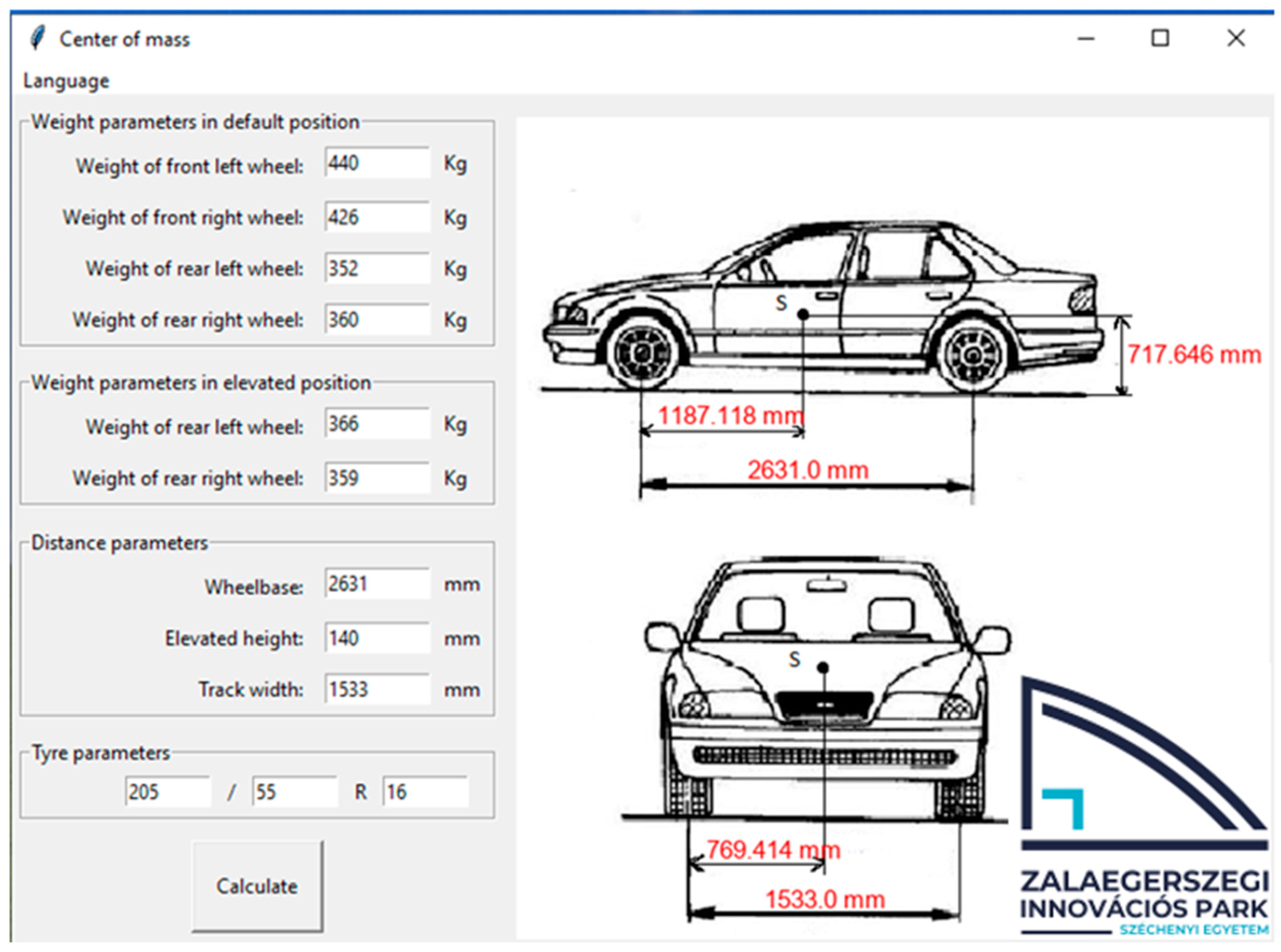
Based on the calculations performed by the software, the following centre of gravity coordinates were obtained for a Volkswagen e-Golf electric vehicle:
- Longitudinal centre of gravity (Sh): 1187.118 mm;
- Transverse centre of gravity (Sk): 769.414 mm (measured from the right side);
- Vertical centre of gravity (Sm): 717.646 mm.
The obtained results are consistent with the symmetrical layout of the vehicle and the weight distribution resulting from the central placement of the battery pack. Based on the calculated value of Sk = 769.414 mm and a track width of b = 1533, the lateral offset of the centre of gravity from the geometric centreline is approximately 2.9 mm. This value falls well within the typical range reported for compact electric vehicles, where lateral offsets of less than 10–15 mm are generally considered negligible in terms of handling balance. Such a small deviation indicates a nearly ideal left–right mass symmetry, contributing to predictable cornering behaviour and reduced yaw asymmetry during dynamic manoeuvres.
To further validate the measurement-based results, the computed CoG coordinates were compared with values obtained from an IPG CarMaker simulation model of the same vehicle. The comparison (Table 2) showed an excellent agreement in both the longitudinal and lateral directions, while the vertical CoG position differed only by a few millimetres. Such a small deviation is within the expected tolerance range for static measurement methods and indicates that the applied axle-load procedure provides results consistent with those produced by high-fidelity simulation environments. This agreement supports the reliability of the proposed approach and demonstrates that the method accurately captures the vehicle’s actual mass distribution for engineering and testing applications.
Table 2.
Comparison of simulation-based and measured data.
To illustrate the influence of tyre deformation on the vertical centre of gravity coordinate, the vertical CoG was additionally calculated assuming a rigid wheel, i.e., neglecting tyre deflection. Since tyre deformation primarily affects the effective wheel radius, its influence is reflected almost exclusively in the vertical CoG coordinate, while the longitudinal and lateral positions remain unchanged.
When tyre deformation was neglected, the calculated vertical CoG coordinate increased from 717.646 mm to 723.283 mm, resulting in a difference of 5.637 mm. This deviation is larger than the difference observed between the tyre-corrected measurement result and the simulation-based value. Therefore, accounting for tyre deformation significantly improves the accuracy and reliability of the static axle-load-based centre of gravity determination.
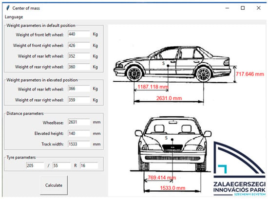
In addition to providing numerical data, the software includes a graphical display that clearly illustrates the position of the centre of gravity on a schematic top view (Figure 4). This visualisation is particularly useful for educational and development purposes, as it provides immediate feedback on how variations in weight distribution affect the vehicle’s balance.
Figure 4.
Program filled with input data and the visual display of the centre of gravity position.
The obtained results indicate that the applied method and the developed software are suitable for the fast, accurate, and safe determination of the centre of gravity in electric vehicles. The procedure can be effectively utilised for development, diagnostic, and educational purposes, as it provides reliable results with minimal equipment requirements and limited user interaction. This reliability is demonstrated by the comparison with simulation-determined coordinates, where discrepancies were observed only in the vertical coordinate and were limited to just 3 mm, confirming the accuracy and trustworthiness of the measurements. The software surface shown in Figure 4 highlights these findings by visually and numerically presenting the spatial positions of the centre of gravity coordinates. This representation facilitates a clearer understanding of the measurements, allowing users to directly interpret the location of the centre of gravity in three-dimensional space and supporting more informed analysis. In particular, for the lateral (transverse) centre of gravity coordinate, the figures indicate the reference wheel from which the distance is measured, which is a critical detail for applying this method accurately.
5. Conclusions
The objective of this study was to develop an accurate, reliable, and practically applicable method for determining the centre of gravity (CoG) of electric vehicles. A static CoG determination approach based on axle-load measurements was implemented, explicitly considering wheel deflection to improve the accuracy of the vertical CoG coordinate. The developed software supports the method by automating the calculation of three-dimensional CoG coordinates, reducing human error, and providing a clear visualisation of the results. A lifting height of 14 cm was identified as an appropriate compromise between measurement safety and sufficient axle-load redistribution, enabling reliable CoG determination without imposing excessive structural loading on the vehicle. Comparison with simulation-based reference values revealed a minimal deviation of approximately 3 mm in the vertical coordinate, confirming the validity and reliability of the proposed approach.
The novelty of this study lies primarily in the adaptation and quantitative justification of a static axle-load-based CoG determination methodology for electric vehicles, including the explicit assessment of wheel deflection effects and the validation of a safe and sufficient lifting height. While the developed software itself does not constitute a standalone scientific novelty, it plays an important supporting role by facilitating practical implementation, ensuring repeatability, and enhancing result interpretation. The proposed methodology is not vehicle-specific, but is intended to be applicable to passenger vehicles with fixed mass distribution, which is characteristic of electric vehicles.
It should be noted that the selected lifting height was chosen for engineering measurement purposes and differs from the larger tilt angles prescribed in UNECE Regulation No. 66 Annex 3, which are conservative by design and intended for regulatory rollover certification across a wide range of vehicle types, including those with moving fluid masses. The present approach does not aim to replace such regulatory procedures, but rather to provide an accurate, laboratory-based CoG determination method suitable for vehicle development, testing preparation, and educational applications. Future research may investigate the influence of larger lifting angles using alternative test rigs that avoid excessive structural loading, in order to further align laboratory-based measurements with regulatory frameworks.
The primary limitation of the method is its current applicability to electric vehicles, where the stationary position of the battery ensures stability of the vertical CoG coordinate. Extension to internal combustion engine vehicles would require explicit consideration of fuel movement effects. Potential applications of the proposed approach include accurate sensor placement and test preparation for vehicle dynamics investigations, such as rollover and stability assessments, where precise knowledge of the CoG enhances test validity while minimising influence on vehicle behaviour.
Author Contributions
Conceptualization, methodology, investigation, writing-original draft preparation, writing-review and editing, visualization, B.B.; software, visualization, D.J. All authors have read and agreed to the published version of the manuscript.
Funding
This research was funded by Széchenyi István University. The APC was funded by Széchenyi István University.
Institutional Review Board Statement
Not applicable.
Informed Consent Statement
Not applicable.
Data Availability Statement
The original contributions presented in this study are included in the article. Further inquiries can be directed to the corresponding author.
Conflicts of Interest
The authors declare no conflicts of interest.
References
- Previati, G.; Mastinu, G.; Gobbi, M. Mass, Centre of Gravity Location and Inertia Tensor of Electric Vehicles: Measured Data for Accurate Accident Reconstruction. World Electr. Veh. J. 2024, 15, 266. [Google Scholar] [CrossRef] [Scilit]
- Suspension Secrets. “How to Calculate Centre of Gravity Position”. Available online: https://suspensionsecrets.co.uk/how-to-calculate-centre-of-gravity-position/ (accessed on 4 July 2025).
- Lin, C.; Gong, X.; Xiong, R.; Cheng, X. A novel H∞ and EKF joint estimation method for determining the center of gravity position of electric vehicles. Appl. Energy 2017, 194, 609–616. [Google Scholar] [CrossRef] [Scilit]
- Widner, A.; Bári, G. Comparison of Center of Gravity Height Estimation Methods. In Proceedings of the Third Vehicle and Automotive Engineering conference (VAE2020), Miskolc, Hungary, 25–26 November 2020; pp. 293–301. [Google Scholar] [CrossRef] [Scilit]
- Fan, X.; Zhang, M. A New Method for Static Measurement of Two Axles Vehicle Centroid Height. Recent Patents Eng. 2021, 14, 629–635. [Google Scholar] [CrossRef] [Scilit]
- Bixel, R.A.; Heydinger, G.J.; Durisek, N.J.; Guenther, D.A.; Novak, S.J. Developments in Vehicle Center of Gravity and Inertial Parameter Estimation and Measurement. SAE Technical Paper 950356, 1995. Available online: https://saemobilus.sae.org/papers/developments-vehicle-center-gravity-inertial-parameter-estimation-measurement-950356 (accessed on 7 July 2025).
- Winkler, C.B.; Campbell, K.L.; Mink, C.E. Center of Gravity Height: A Round-Robin Measurement Program. Available online: https://deepblue.lib.umich.edu/bitstream/handle/2027.42/913/80554.0001.001.pdf?sequence=2&isAllowed=y (accessed on 7 April 2025).
- Mango, N. Measurement & Calculation of Vehicle Center of Gravity Using Portable Wheel Scales. Available online: https://saemobilus.sae.org/papers/measurement-calculation-vehicle-center-gravity-using-portable-wheel-scales-2004-01-1076 (accessed on 10 July 2025).
- Belloni, M.; Vignati, M.; Sabbioni, E. Analysing the Effect of Chassis Torsional Flexibility on the Rollover Threshold of a Multi-Purpose Agricultural Vehicle. Vehicles 2024, 6, 415–432. [Google Scholar] [CrossRef] [Scilit]
- Grzebieta, R.; Rechnitzer, G.; Simmons, K. Quad Bike Performance Project (QBPP) Part1: Static Stability Test Results. Available online: https://www.researchgate.net/publication/283330978_Quad_Bike_Performance_Project_QBPP_Part_1_Static_Stability_Test_Results?channel=doi&linkId=5634175208ae758841121eb5&showFulltext=true (accessed on 11 July 2025).
- Fuerbeth, U. Centre of gravity of motor vehicles. Forensic Sci. Int. 2024, 361, 112073. [Google Scholar] [CrossRef] [Scilit] [PubMed]
- Siuru, W.D. Computation of Vehicle Center of Gravity. 1988. Available online: https://saemobilus.sae.org/papers/computation-vehicle-center-gravity-881741 (accessed on 17 July 2025).
- Solmaz, S.; Akar, M.; Shorten, R. Online Center of Gravity Estimation in Automotive Vehicles using Multiple Models and Switching. In Proceedings of the 2006 9th International Conference on Control, Automation, Robotics and Vision, Singapore, 5–8 December 2006; pp. 1–7. [Google Scholar] [CrossRef] [Scilit]
- Wu, F.; Sun, C.; Li, H.; Zheng, S. Real-Time Center of Gravity Estimation for Intelligent Connected Vehicle Based on HEKF-EKF. Electron. 2023, 12, 386. [Google Scholar] [CrossRef] [Scilit]
- Wittmer, K.; Sawodny, O.; Henning, K.-U. Model-Based Estimation of Vehicle Center of Gravity Height and Load. J. Dyn. Syst. Meas. Control. 2023, 145, 1–16. [Google Scholar] [CrossRef] [Scilit]
- Germann, S.; Isermann, R. Determination of the Centre of Gravity Height of a Vehicle with Parameter Estimation. IFAC Proc. Vol. 1994, 27, 563–568. [Google Scholar] [CrossRef] [Scilit]
- Huang, X.; Wang, J. Center of gravity height real-time estimation for lightweight vehicles using tire instant effective radius. Control. Eng. Pract. 2013, 21, 370–380. [Google Scholar] [CrossRef] [Scilit]

Disclaimer/Publisher’s Note: The statements, opinions and data contained in all publications are solely those of the individual author(s) and contributor(s) and not of MDPI and/or the editor(s). MDPI and/or the editor(s) disclaim responsibility for any injury to people or property resulting from any ideas, methods, instructions or products referred to in the content. |
© 2026 by the authors. Licensee MDPI, Basel, Switzerland. This article is an open access article distributed under the terms and conditions of the Creative Commons Attribution (CC BY) license.