


Abstract
Seasonal groundwater rise of 2.5–3.0 m leads to full saturation of the lakeside slope of the railway embankment, significantly reducing the strength of clayey–sandy loam layers. Laboratory shear tests showed that saturation decreases the internal friction angle from 24–26° to 16–19°, while effective cohesion drops from 12–18 kPa to 0–3 kPa, identifying the 3–6 m depth interval as the critical weak zone. These parameters were incorporated into PLAXIS 2D/3D hydro-mechanical models to assess the embankment behaviour under three scenarios: natural conditions, high water level, and reinforced configuration. Under elevated water levels, lateral displacement toward the lakeside increased to 0.16–0.21 m, and the plastic strain zone expanded by a factor of 2.4, reducing the safety factor from FS ≈ 1.32 to below 1.10. The proposed stabilization system—replacement of a 1.5 m weak layer, installation of geotextile reinforcement, and application of a bituminous waterproofing layer—substantially improved stability, reducing maximum lateral displacement to 0.12 m (≈43% reduction) and restoring the safety factor to FS = 1.25–1.40. The results demonstrate that low-cost geosynthetic barriers provide an effective and practical engineering solution for maintaining the long-term stability of railway embankments exposed to seasonal inundation.
1. Introduction
Railway transport is one of the key pillars of modern mobility systems, providing highly efficient, reliable, and energy-saving long-distance freight and passenger transportation [1]. At the international level, major railway corridors support transboundary trade flows and constitute an essential component of global logistics chains. Therefore, ensuring the long-term reliability and stability of railway networks is a strategic requirement for transport safety and sustainable economic development [2].
However, the performance of railway infrastructure is strongly influenced by natural environmental factors. In particular, the stability of the track substructure and embankment is highly sensitive to climatic, hydrological, and geotechnical conditions [3,4]. Processes such as water-level rise, soil rewetting, seepage- and wind-driven erosion, and the reduction in shear strength of saturated clayey layers may significantly weaken the stability of railway embankments, causing settlement, lateral spreading, and slope failures [5,6]. These deformations lead to operational speed restrictions, increased maintenance costs, logistic delays, and higher safety risks.
Geotechnical research on railway embankments has been widely conducted worldwide, with particular focus on dynamic loading behaviour, soil property degradation, and structural stability. Several studies investigated embankments interacting with retaining structures under dynamic loads and discussed methods for improving stability [7]. The use of innovative reinforcing elements—polymeric inclusions, polyurethane foams, and recycled rubber aggregates—to enhance track-bed rigidity has been explored by [8]. In cold regions, the evolution of the dynamic elastic modulus of subgrade soils under freeze–thaw cycles has been comprehensively studied [9]. Numerical investigations by Son and co-authors [10] have demonstrated the role of slope retaining systems in limiting lateral displacement during embankment construction. Collectively, these studies highlight the importance of addressing all structural elements of the railway subgrade—ballast, subballast, natural foundation soils, and reinforcing layers—in an integrated manner.
In recent years, the sustainable development of railway infrastructure has gained significant attention. Several authors have argued that rail transport can considerably reduce the carbon footprint of national transport systems, especially in developing countries, where railway development can shift freight from road and air towards lower-emission modes [11,12]. Nevertheless, the infrastructure itself—track beds, embankments, bridges, and depots—requires large quantities of aggregates, cement, steel, and heavy machinery, resulting in substantial environmental impacts during construction and maintenance [13]. Life-cycle assessment (LCA) studies show that material optimization, the use of recycled aggregates, and extending maintenance intervals are key strategies for “greening” railway infrastructure [14,15].
The reuse of construction and demolition waste, glass, rubber particles, steel slags, and other secondary materials as ballast, subballast, or embankment fill has been actively investigated [16]. Tire-derived aggregates (TDA), for example, improve the damping properties of a ballast, reduce vibration propagation, and limit particle degradation [8,14]. Laboratory and field studies confirm that rubberized ballast decreases ground-borne vibrations and slows the rate of track-geometry deterioration [17,18]. However, the inclusion of rubber often reduces shear strength and stiffness, potentially increasing excessive settlement and lateral spreading [8,12,14]. To overcome these drawbacks, rubber–soil mixtures treated with polyurethane binders or similar agents have been proposed [19], forming composite layers suitable even as a ballastless track subbase due to their combined damping capacity and mechanical stability [17,20].
Another important direction is the use of geosynthetics—geotextiles, geogrids, geomembranes, and geocells—for reinforcing weak subgrades, improving load distribution, limiting lateral spreading, and preventing erosion [21,22]. Numerous field and numerical studies have shown that geocell-reinforced layers reduce settlement, mitigate stiffness transitions in bridge–embankment approaches, and enhance overall stability [23,24]. Planar geosynthetics, spanning geotextiles, geogrids, and geocomposites, are also widely used, including in pile-supported embankments, where the membrane effect redistributes loads between soil and piles, reducing deformation [25,26].
Although these studies confirm the effectiveness of polymeric and geosynthetic reinforcement systems, they often rely on costly engineered geomaterials, which may be economically challenging for developing countries or long coastal railway segments. Moreover, a majority of previous research focuses on dynamic loads, ballast behaviour, or pile-supported embankments; very few studies address saturation-induced instability in lakeshore clayey embankments and the use of low-cost polymeric waterproofing layers as a mitigation measure [27].
Field and numerical observations from water-affected railway sections show that prolonged saturation of the lakeside slope and the embankment foundation drastically reduces clayey soil strength parameters: the friction angle φ and cohesion c may decrease several-fold [28,29]. In such cases, simple elastic–plastic or classical Boussinesq models fail to capture the actual mechanical behaviour. Therefore, three interacting aspects must be considered simultaneously:
- the dependence of shear strength parameters on degree of saturation;
- the hydraulic regime (infiltration, seepage, and wave action);
- cyclic-dynamic train loading [30].
Finite element modelling (FEM) offers a suitable framework for integrating these processes. Many authors have successfully constructed 2D and 3D FEM models of railway embankments to simulate load distribution, deformation, and stress fields under varying train loads and water levels [31,32]. Nevertheless, the application of inexpensive polymeric waterproofing membranes (bitumen-based or roll-type) beneath the lakeside slope and near the sleeper zone remains insufficiently explored [33].
In water-impacted settings such as the Balqash region, clayey soils remain saturated for prolonged periods, and wave-induced erosion intensifies instability. The proposed approach of installing a low-cost waterproofing layer aims to limit lake-side infiltration, reduce the saturated zone width, and slow the degradation of shear strength parameters. Based on findings from the literature, such a barrier could delay the advancement of the saturation front and reduce the likelihood of shear failure [34].
Despite extensive research on railway subgrade reinforcement technologies—rubber aggregates, geocells, geogrids, and optimized ballast composition—these studies often do not cover the unique hydrological conditions of lakeshore railway corridors. Seasonal water-level fluctuations, wind-induced waves, and long-term saturation significantly challenge the stability of embankments in regions underlain by soft clayey soils. These issues are particularly relevant for the Balqash corridor of the Kazakhstan–China railway, a critical segment of the international freight corridor, where annual freight volumes have grown by 48% in the last five years and reached 32 million tons, with an additional 13% increase in early 2025 alone [35]. Such growth intensifies dynamic loads on the track substructure and increases the importance of embankment stability assessment.
Given these challenges, a comprehensive geotechnical investigation is required to understand the mechanical behaviour of saturated clayey soils, quantify shear strength parameters through laboratory tests, and simulate the embankment’s stress–strain response under hydromechanical loading using advanced FEM tools such as PLAXIS [36,37].
The present study aims to analyze the stress–strain behaviour of railway embankments constructed on water-sensitive clayey soils in the Balqash region through laboratory shear testing and FEM-based numerical modelling, and to assess the effectiveness of a low-cost polymeric waterproofing and reinforcing system installed along the lakeside slope. The findings support the development of economical and technically effective engineering solutions for stabilizing railway embankments under seasonal inundation and increasing freight traffic.
To achieve this aim, the following tasks were undertaken:
- Determination of shear strength parameters of Balqash clayey soils through laboratory testing, primarily using direct simple shear (DSS) tests under controlled normal stress conditions;
- FEM of the embankment’s stress–strain behaviour under elevated water levels in PLAXIS 2D;
- Comparative analysis of models with and without a polymeric waterproofing layer, focusing on saturation extent, embankment stability, and potential sliding mechanisms;
- Development of engineering recommendations for cost-effective and technically robust stabilization of railway embankments in seasonally flooded zones.
This study makes the following key contributions: (i) it focuses on seasonal groundwater saturation induced by adjacent lakes rather than short-term flooding events; (ii) it combines laboratory-derived saturation-dependent soil parameters with finite element modelling to assess embankment behaviour; and (iii) it evaluates the practical effectiveness of low-cost waterproofing solutions suitable for long railway corridors.
2. Materials and Methods
2.1. Geographical and Physical Characteristics of the Study Area
The study area is located in the southeastern part of the Republic of Kazakhstan and covers a shoreline section of the Dostyk–Mointy international railway corridor situated near the southern coast of Lake Balkhash (Figure 1).
Figure 1.
Location of the study area near Lake Balkhash and topographic characteristics of the railway embankment erosion zone.
Gently sloping plains, coastal accumulative formations, and absolute elevations ranging from 366 to 435 m characterize the geomorphological setting of the Balkhash region. Because the railway line lies in close proximity to the lake level, the embankment is directly exposed to natural hydrological and climatic impacts. The “railway embankment erosion zone” indicated in Figure 1 corresponds to the area of the strongest lake–railway interaction [38].
The hydrological regime of Lake Balkhash is defined by high evaporation rates, pronounced seasonal water-level fluctuations, and considerable climatic variability. Among the natural environmental loads acting on the embankment, the regional wind regime plays a dominant role [39].
According to long-term meteorological observations:
- the prevailing annual wind directions are west and northwest;
- the mean annual wind speed is 4–6 km/h;
- wind gusts periodically reach 10–15 km/h and occasionally exceed these values.
During summer (July–August), strong winds may originate from the east and southeast, contributing to overall lake circulation and wave activity. However, as illustrated in Figure 1, the prevailing west and northwest winds are the primary drivers pushing lake water and wave action toward the railway embankment, thereby exerting the most significant hydrodynamic impact on the lakeward slope.
Persistent west–northwest winds, combined with intensified summer easterly flows, significantly increase wave-induced pressures along the shoreline. This wave action generates recurrent dynamic loads on the lake-facing slope of the embankment, accelerating erosion and scouring processes (Figure 2). As a result, the lower part of the embankment remains within a long-term saturation zone, leading to a reduction in the shear strength of the clayey soil layers.
Figure 2.
Wave impact parameters.
Figure 2 presents the structural schematic of the embankment’s lakeward slope. The figure illustrates the main slope, berm, counter-berm, rock mass, mean multi-year water level, and high-water level. This schematic is essential for evaluating hydrostatic loading, seepage processes, and stress–strain responses associated with water-level fluctuations.
2.2. Engineering-Geological Characteristics of the Study Area
The study area is located on the southern shoreline of Lake Balkhash, within a weak engineering-geological zone situated approximately 4–6 m above the long-term mean water level of the lake. The geological structure consists of Cenozoic and Quaternary coastal-accumulative deposits. The lithological profile is dominated by fine-grained soils, including medium- to high-plasticity silty clays and clay loams (Ip = 17–25%), as well as sandy loam–clayey interlayers. These deposits correspond to saline lacustrine clayey formations widely distributed around Balkhash and are characterized by chloride–sulfate salinity (Cl/SO4 = 1.0–1.5), placing them in the moderately saline category.
The paleo-lacustrine, loess-like sediments in the area are weakly cemented and prone to rapid loss of structural strength under seasonal wetting, with settlement magnitudes reaching up to 70 cm. The railway corridor, located approximately 180–250 m from the shoreline, is therefore influenced by lake water-level fluctuations acting predominantly on the lakeside slope. In some sections, variations in groundwater and external water levels on both sides of the embankment may occur depending on seasonal conditions. During periods of inundation, additional settlements of up to 70 cm have been observed. Due to the absence of a drainage system, erosional gullies develop along slopes, while moisture accumulation in the subgrade leads to “dish-shaped” ballast deformation.
These engineering-geological conditions define the primary causes of settlement, lateral displacement, and seasonal instability of the shoreline embankment. In particular, the strength deterioration of moisture-sensitive clayey and sandy–clayey layers located near the lake poses a critical threat to the long-term stability of the railway embankment.
2.3. Sampling Procedure and Preparation for Laboratory Testing
To evaluate the degradation of soil structure caused by water saturation on the lakeward side of the railway embankment, a series of field investigations was conducted. Undisturbed soil samples were extracted from the embankment body by rotary drilling using thin-walled steel sampling tubes (Shelby-type samplers, Forsun Ultra-hard Material Industry Co., Ltd., Changsha, Hunan, China) with an internal diameter of 70 mm and a length of 500 mm, down to a depth of 6 m, with sampling intervals of 1.5 m. The samples were collected in accordance with standard requirements and preserved in hermetically sealed cylindrical containers to maintain their natural moisture content, intact structure, and in situ stress–strain state (Figure 3a–d).
Figure 3.
Preparation of undisturbed soil samples and laboratory equipment used in this study: (a) Extraction of an undisturbed cylindrical soil core from the sampling mould; (b) one-dimensional compression apparatus GT 1.1.9 (manufactured by NPP “GEOTEK”, Russia) used for oedometer testing; (c) multi-channel consolidation testing stand (NPP “GEOTEK”, Russia) used for saturation and consolidation stages; (d) computer interface for real-time recording of compression–consolidation data.
Vertical strain was measured using a high-precision displacement transducer integrated into the compression and consolidation testing apparatus, with continuous digital recording of deformation throughout the entire loading and consolidation process. Figure 3a–d illustrates representative undisturbed soil specimens and the main laboratory equipment used in this study, highlighting the sample handling, preparation stages, and the instrumentation employed for compression–consolidation testing prior to mechanical analysis.
After delivery to the laboratory, the undisturbed soil cores were stored in a sealed, humidity-controlled environment at constant temperature in order to preserve their natural moisture content and allow for stress equilibration prior to testing. The specimens were then trimmed to the dimensions required for mechanical testing. The procedure of removing the specimen from the sampling mould and performing the initial preparation is illustrated in Figure 3a; at this stage, the soil core was carefully extracted from the metal sampling tube, excess material was removed, and the specimen was shaped to fit the testing ring without disturbing its internal structure.
All laboratory investigations were conducted at the accredited laboratory of “KazStroyGeologiya LLP”. One-dimensional compression parameters were determined using a standard oedometer apparatus GT 1.1.9 (manufactured by NPP Geotek (Scientific Production Enterprise), Penza, Russia), as shown in Figure 3b. This device allows for stepwise vertical loading of soil specimens and enables the determination of deformation characteristics, including constrained modulus, oedometric modulus, and consolidation behaviour.
For sample saturation, preloading stabilization, and evaluation of consolidation processes, a multi-channel consolidation testing system was employed (Figure 3c). This system allows for the controlled application of vertical stress and continuous digital monitoring of deformation and pore pressure response during consolidation.
The entire compression–consolidation process was monitored and recorded in real time using a dedicated computer interface (Figure 3d), ensuring high accuracy, repeatability, and traceability of test results.
The equipment supports both downward and upward saturation schemes, enabling accurate determination of soil porosity, degree of saturation, and initial structural strength parameters.
The laboratory tests provided a comprehensive set of geotechnical parameters:
- natural and limit water contents (W, Wl, Wp);
- plasticity characteristics (Ip, IL);
- density-related parameters (ρn, ρd, ρs);
- void ratio and saturation indices (e, n, Sr);
- shear strength parameters (c, φ, τmax) obtained from direct simple shear (DSS) tests under three different normal stress levels, selected to represent the in situ stress conditions acting predominantly along potential horizontal and shallow slip surfaces within the embankment foundation;
- compressibility and deformation moduli (E, Eoed, Ek);
- consolidation parameters, including the coefficient of consolidation (cv) and the secondary compression coefficient (cα).
Direct simple shear (DSS) testing was used to evaluate the shear response of the soils under stress conditions representative of the embankment. Tests were performed under controlled normal stress following ASTM D6528-17 [40], allowing for vertical deformation to develop during shearing.
Although DSS apparatuses are commonly associated with undrained shear testing of soft soils, modern systems allow for the control of vertical deformation during shearing, enabling the derivation of stress–strain relationships representative of drained or partially drained behaviour. In the present study, the DSS tests were used to obtain equivalent shear strength parameters (φ and c) suitable for engineering interpretation and numerical modelling, rather than intrinsic drained strength parameters in the classical triaxial sense.
Therefore, the obtained shear strength parameters should be interpreted as engineering shear resistance values, reflecting the stress–strain response of the soil under conditions representative of field loading and deformation constraints. This approach is consistent with the methodology described in [40] and is appropriate for the comparative assessment of embankment stability under varying saturation conditions.
At each sampling depth (1.5, 3.0, 4.5, and 6.0 m), at least three undisturbed specimens were tested under both natural and fully saturated conditions. Direct simple shear tests were performed using three normal stress levels representative of in situ overburden pressures within the embankment foundation. This testing scheme ensured a consistent and statistically comparable evaluation of shear strength parameters and their variation with depth and saturation state.
These experimentally derived parameters were subsequently implemented as input data in the PLAXIS 2D numerical model (version 20.0.0.119) to simulate the hydromechanical stress–strain behaviour of the railway embankment under varying saturation conditions.
The obtained values form the foundational input set for the finite element (FEM) modelling framework, enabling a quantitative assessment of the weakening mechanism induced by lake-driven groundwater rise and for evaluating the overall stability of the embankment structure.
2.4. Hydrological and Climatic Data
Analysis of long-term meteorological records for the study area demonstrates that the wind regime over the Balkhash region exhibits a pronounced seasonal variability. The prevailing winds throughout the year originate from the west–northwest sector, which is the primary driver pushing lake water toward the railway embankment slope. Mean wind speeds typically range between 0.8 and 2.2 m/s, while the highest seasonal fluctuations during spring–summer months commonly fall within the 3–4 m/s interval.
The annual wind-rose distribution [39] confirms the dominance of the west and northwest directions. Winds from these sectors intensify wave run-up against the lakeward slope of the embankment, resulting in increased wave-induced pressures and enhanced infiltration loading during peak seasonal periods. Collectively, the data indicate that wind forcing from the west–northwest direction is the main contributor to elevated hydrodynamic impacts acting on the railway embankment.
Under such hydrological conditions, engineering measures aimed at controlling water infiltration and stabilizing the embankment body become essential. Geosynthetics are widely used in road and railway embankments to improve stability, control deformation, and regulate water flow within the soil structure. Geotextiles are commonly applied for separation and filtration, preventing the migration of fine particles while allowing for controlled drainage. Geogrids and geocomposites are primarily used for reinforcement, enhancing load distribution and increasing resistance to shear deformation. Drainage geonets and geomembranes are employed to facilitate water dissipation and to act as impermeable barriers where infiltration control is required. In the present study, a geotextile layer and a bitumen-based waterproofing membrane were selected to provide reinforcement and limit lake-induced water infiltration along the embankment slope.
To mitigate the degradation of the embankment under hydrological loading, several protective and reinforcement measures were implemented at the site. First, the upper 1.5 m of the embankment’s lakeward zone, composed of moisture-sensitive clayey soils, was partially excavated and replaced with a mechanically stronger granular fill material, selected to reduce excessive wetting and limit secondary dynamic deformation induced by traffic loads.
Across the replaced layer, a horizontally placed geotextile sheet with a density of 300 g/m2 was installed, extending from the lakeward toe toward the base of the first rail. The appearance of the polyester needle-punched geotextile material employed in the embankment protection works is shown in Figure 4a. The geotextile installation concept and its position within the embankment structure are schematically illustrated in the Section 3.1 using the numerical model geometry.
Figure 4.
Waterproofing and reinforcing materials used to protect the embankment from water impact: (a) Needle-punched polyester geotextile; (b) bitumen-based roll waterproofing membrane (Ruberoid).
The geotextile was selected based on its material type and nominal physical properties, which are summarized in Table 1. These properties are reported for material identification purposes only and are not intended to quantify or predict the mechanical performance of the reinforced embankment.
Table 1.
Technical specifications of the needle-punched polyester geotextile used for embankment reinforcement.
To further protect the lakeward slope of the embankment from direct hydraulic impact, the entire face of the slope—starting from the ballast crib and extending down to the toe—was covered with a roll-type waterproofing membrane (bitumen-based roofing felt). This protective layer was adopted to limit direct water contact with the slope surface and to reduce water ingress into the clayey embankment materials. The appearance of the bitumen-based waterproofing membrane used in the protection work is shown in Figure 4b.
The selection of the waterproofing material was based on its nominal hydraulic, thermal, and durability-related characteristics, which are summarized in Table 2 to document the suitability of the selected product for the applied engineering conditions.
Table 2.
Key technical specifications of the bitumen-based waterproofing membrane.
In addition, to prevent membrane detachment under wave action and to ensure reliable anchorage, the lakeward slope was covered with a stone–concrete revetment. This protective layer was intended to stabilize the waterproofing system, provide additional weight to the slope, and mitigate surface erosion induced by wave–wind action.
The location and role of the stone–concrete revetment within the embankment system are illustrated schematically in the Section 3.1.
The investigated railway line is a single-track corridor subjected to mixed freight traffic, including various types of locomotives and freight wagons operating under international transit conditions. In order to reflect the range of rolling stock currently in service on this route, several representative vehicle configurations were considered.
The load parameters summarized in Table 3 are not intended to define extreme design scenarios, but rather to provide a comparative representation of the normalized rail loading conditions associated with different rolling stock types operating on the line. This approach allows for the adopted numerical model to account for realistic operational variability while remaining within conservative loading assumptions.
Table 3.
Representative load parameters of rolling stock considered for comparative assessment of rail loading conditions.
2.5. Numerical Modelling Framework (PLAXIS 2D FEM)
To evaluate the stress–strain behaviour of the railway embankment under varying degrees of water saturation, a numerical analysis was performed using the PLAXIS 2D finite element software package (version 20.0.0.119), which is widely applied in geotechnical modelling. The simulations were conducted within the Deformation-Plasticity calculation mode, adopting the classical Mohr–Coulomb elastic-perfectly plastic constitutive model. The selection of the Mohr–Coulomb model was based on the type of geomaterials involved and the available laboratory data, as this model allows for direct incorporation of shear strength parameters (φ, c) obtained from laboratory shear tests. Although more advanced constitutive models implemented in PLAXIS also make use of Mohr–Coulomb strength parameters, they require additional stiffness-related parameters that were not available for the present study. Therefore, the Mohr–Coulomb model was adopted as a baseline constitutive representation to capture the primary stress–strain response of the embankment materials within the defined scope of the analysis.
The numerical modelling procedure in PLAXIS followed a standard stepwise workflow. First, the geometric configuration of the embankment and the stratified soil profile were defined based on the engineering-geological cross-section. Second, material models and soil parameters derived from laboratory testing were assigned to each layer. Third, boundary conditions and initial stress states were generated using the K0-procedure. Subsequently, hydraulic conditions corresponding to different lake water levels were introduced. Finally, external loads representing railway traffic were applied, and the deformation, displacement, and safety analyses were performed for each calculation phase.
Although the Mohr–Coulomb model has known limitations in representing the complex stress–strain behaviour of saturated fine-grained soils, it was adopted in this study due to its robustness, widespread engineering acceptance, and suitability for comparative stability and displacement analyses within the scope of the present study.
The embankment and the surrounding soil mass were discretized using 15-node triangular elements, which provide high numerical accuracy, particularly in zones with steep deformation gradients, such as the saturation front, the embankment toe, and the interfaces between soil, geotextile, and the waterproofing layer. Hydrological conditions were incorporated explicitly; the lakeward boundary was modelled using phreatic level and flow boundary conditions to represent seepage inflow. Two water-level conditions were simulated: (i) the multi-year mean lake level and (ii) the high-water condition representing the seasonal rise, thereby capturing the associated increase in hydraulic gradients and wave-induced pressure.
Vertical dynamic loads from rolling stock were applied according to the design axle pressures introduced earlier. Equivalent track loads (pn, kPa) for locomotives and freight wagons were implemented as line loads acting along the rail alignment. This loading configuration enables realistic estimation of settlement, lateral displacement, and the formation of plastic zones within the embankment body.
The protective geosynthetic components used in the field were also incorporated into the numerical model. The geotextile installed in the upper embankment zone was represented using the dedicated Geotextile/Geogrid element, with its tensile stiffness and allowable strain assigned based on laboratory test results and manufacturer-provided specifications (see Table 1).
The bituminous waterproofing layer (Ruberoid) placed along the lakeward slope was simulated as a thin, very-low-permeability interface. Under the assumed saturated conditions, this interface was intended to limit direct water exchange and seepage at the slope surface and to control near-surface hydraulic boundary conditions, rather than to alter the degree of saturation within the deeper clayey layers.
Overall, the PLAXIS 2D modelling framework allowed for a comprehensive evaluation of the embankment’s mechanical response under water saturation, hydraulic loading, and operational railway loads. The numerical results enabled identification of stress concentrations, plastic deformation zones, and settlement patterns within the weak clayey strata, forming a basis for the engineering recommendations presented in subsequent sections.
3. Results and Discussion
3.1. Physical State Parameters and Phase Composition of the Soil
To characterize the in situ geotechnical conditions of the railway embankment, undisturbed soil samples were taken at depths of 1.5 m, 3.0 m, 4.5 m, and 6.0 m. These depths represent the full vertical profile of the embankment body and enable a comparative assessment of the physical (including consistency) and strength behaviour of the individual soil layers.
The evaluation of physical soil properties—including density, moisture content, void structure, and consistency characteristics—revealed that these parameters play a decisive role in the mechanical performance of the embankment. Their values govern the soil’s shear strength, permeability, compressibility, and response under cyclic and static loading. Because these characteristics are strongly interdependent, proper engineering interpretation of the laboratory results requires a clear definition of the classical physical state parameters and their mathematical formulation.
The engineering meaning of these parameters is derived from the phase composition of soil, representing the proportions of water, air, and solid particles within the soil structure. The calculation of these quantities follows the conventional relationships widely used in soil mechanics, as summarized schematically in Figure 5.
Figure 5.
Three-phase soil composition: Air, water, and solid skeleton.
To characterize the geotechnical state of the railway embankment, soil samples were collected at depths of 1.5 m, 3.0 m, 4.5 m, and 6.0 m, covering the full vertical profile of the embankment foundation. The laboratory results are interpreted below with reference to the variation in physical and strength-related properties between the identified soil layers.
Among the measured physical parameters, dry density (ρd) was used as a key reference indicator for comparing the condition of the soil layers and interpreting the laboratory results [41,42].
3.2. Laboratory Testing Methods and Basic Soil Characterization
The physical parameters were determined in compliance with GOST 25100-2020 requirements [43], whereas deformation characteristics were obtained using standard oedometer-based compression procedures. Shear strength parameters (φ and c) reported in this study (Table 4) were derived exclusively from direct simple shear (DSS) tests performed under controlled normal stress conditions.
Table 4.
Physical and mechanical properties of the railway embankment soils at different depths.
Following the evaluation of basic physical parameters, the consistency properties of the soils were examined based on their Atterberg limits. The liquid limit (WL) and plastic limit (Wp) represent fundamental material properties that do not change for the same soil and were therefore treated as fixed reference indices. These parameters were used to classify the fine-grained soils and to support the interpretation of their consistency state under varying moisture conditions.
Variations in soil behaviour were assessed by relating the natural water content to these fixed limits, allowing for the transition between semisolid, plastic, and liquid consistency states to be evaluated through the Liquidity Index (Figure 6). This approach enables observed changes in mechanical response to be interpreted as a consequence of variations in moisture state, rather than as changes in the intrinsic consistency properties of the soils.
Figure 6.
Schematic representation of consistency states of clayey soils as a function of the Liquidity Index and Plasticity Index.
The use of consistency indices is particularly relevant for describing the seasonal hydrological response of fine-grained soils within the railway embankment, where fluctuations in lake water levels may lead to periodic softening and associated reductions in shear strength without altering the fundamental soil properties.
The plasticity index is defined as the difference between the liquid limit and the plastic limit and provides a standard measure of the range of moisture contents over which a fine-grained soil exhibits plastic behaviour. In this study, (Ip) was used as a classification parameter and was calculated according to Equation (1), following conventional geotechnical definitions [42].
where
Wl—plastic limit and Wp—plasticity index.
This parameter reflects the ductility, structural stability, and the swell–shrink behaviour of clayey and silty soils under varying moisture conditions.
Liquidity Index (IL)—The liquidity index expresses the degree of fluidity of natural soils, indicating the relative position of the in situ moisture content within the plasticity range, as shown in Equation (2):
where
W—natural moisture content.
The liquidity index is a key indicator of the soil’s current consistency state and its sensitivity to seasonal wetting. Together, these parameters not only describe the soil’s rheological response but also help evaluate changes in shear strength and deformation behaviour under moisture variations, which is critical for predicting the performance of the railway embankment under lake-induced hydrological fluctuations [31].
Accordingly, in the subsequent analysis, the obtained physical parameters W, ρ, ρd, ρs, and e were evaluated jointly with the Atterberg limits (WL, WP) and the derived indices (Ip and IL) to assess the engineering condition of each depth layer independently.
The 0–1.5 m layer (stiff, slightly moist sandy loam) represents one of the most stable elements of the embankment foundation. Its natural moisture content (W = 16.1%) is lower than the plastic limit (Wp = 18%), resulting in a negative liquidity index (IL = −0.32) corresponding to a solid-state consistency. Such a condition indicates that the soil skeleton preserves its structural integrity and can resist external loading without noticeable deformation. The relatively low void ratio (e = 0.63) and moderate degree of saturation (Sr = 0.69) indicate an unsaturated and mechanically stable material whose mechanical response is expected to remain relatively stable under typical seasonal moisture fluctuations, although local increases in water content and degree of saturation may occur during rainfall infiltration events. High shear resistance—expressed by an internal friction angle of φ = 21–23° and cohesion c = 23–26 kPa—demonstrates that this layer serves as a load-bearing element providing structural support for the embankment.
The 1.5–3.0 m layer (moist sandy loam) is characterized by deterioration of engineering properties due to seasonal wetting. Its natural moisture content increases to W = 21.36%, approaching the plastic limit (WP = 20%) and producing a liquidity index of IL = 0.23–0.25, corresponding to a stiff-plastic state. This indicates partial softening of the soil structure, weakening of interparticle bonds, and increased susceptibility to shear deformation. The increase in void ratio (e = 0.76) relative to the overlying layer, together with a moderate degree of saturation (Sr ≈ 0.75), indicates that the soil remains unsaturated but exhibits increased sensitivity to moisture variations. These physical transformations result in reduced shear strength: the internal friction angle decreases to φ = 17–21°, and cohesion ranges between 22 and 25 kPa. Consequently, this layer forms a transitional weakened zone that contributes to the initiation of primary deformations at the embankment base.
The 3.0–4.5 m layer (water-saturated clay loam) is identified as the weakest engineering element within the section. The moisture content reaches W = 28%, and the plasticity parameters (WL = 31%, WP = 19%) yield a plasticity index of Ip = 12%. The resulting liquidity index (IL ≈ 0.75) corresponds to a soft-to-plastic flow consistency state, indicating pronounced structural softening associated with elevated pore water pressures and a corresponding reduction in effective stress. The void ratio increases to e = 0.85, and the degree of saturation approaches Sr ≈ 1.0, indicating near-saturated conditions.
These hydrological conditions reduce the internal friction angle to φ = 16–19°. Although the measured cohesion increases to c = 30–35 kPa, this increase primarily reflects apparent cohesion typical of soft saturated clays. Under loading conditions, the reduced effective stress and low frictional resistance govern the shear response, and the increased cohesion does not translate into a proportional increase in mobilized shear strength. This layer, therefore, represents the principal potential sliding zone during periods of elevated lake water levels.
The 4.5–6.0 m layer (high-moisture sandy loam, submerged) exhibits a liquidity index of IL = 1.00, indicating a consistency state close to the liquid limit. Its moisture content (W = 31%) and void ratio (e = 0.76) indicate a soil fabric with an open pore structure and continuous hydraulic contact with the surrounding water, allowing for water exchange without significant hydraulic restraint. A relatively high degree of saturation (Sr = 0.79) reflects pronounced softening and weakening of shear resistance. Although the friction angle ranges between φ = 21–27° and cohesion between c = 27–35 kPa, these parameters are not fully mobilized under field conditions due to the near-saturated state of the soil and elevated pore water pressures, which reduce effective stress and limit the development of shear resistance during loading. As a consequence, this layer forms a structurally vulnerable zone that directly contributes to the lateral displacement on the lakeward slope.
Overall, the variations in Ip, IL, φ, and c across the depth profile reveal that the primary cause of embankment instability is the presence of water-saturated and soft-plastic clayey soils between 3 and 6 m in depth. Seasonal wetting leads to significant structural weakening within these layers, fully explaining the observed mechanisms of lakeward displacement and confirming that stabilization measures must be targeted precisely at this depth interval [42]. Comparison of the obtained strength parameters with standard classification schemes verifies that the identified engineering behaviour of each layer corresponds accurately to its measured consistency state (Figure 7).
Figure 7.
Shear strength classification of soils based on c–φ correlations and liquidity index ranges [41].
As illustrated in Figure 7, increasing the liquidity index (IL) leads to a systematic reduction in both the internal friction angle and cohesion in clayey and sandy loam soils, reflecting the progressive weakening of the soil structure as it transitions toward plastic and near-liquid states. The laboratory results obtained in this study fully align with these established φ–c trends.
The dry, stiff sandy loam at 0–1.5 m (IL = −0.32) represents the most stable layer of the embankment. Its negative liquidity index corresponds to a solid-to-semi-solid state, with strength parameters φ = 21–23° and c = 23–26 kPa, matching the sandy loam field in Figure 7. The low void ratio (e = 0.63) and moderate saturation (Sr ≈ 0.70) indicate limited moisture sensitivity, allowing for this layer to function as a primary stabilizing element.
At 1.5–3.0 m, the moist sandy loam transitions into a stiff-plastic state (IL = 0.23–0.25). Consistent with the φ-c envelopes in Figure 7, shear strength decreases to φ = 17–21° and c = 22–25 kPa. Elevated void ratio (e = 0.76) and Sr ≈ 0.75 indicate increased moisture susceptibility, making this depth a transitional weak zone where seasonal wetting may initiate deformation.
The water-saturated loam at 3.0–4.5 m is the weakest engineering layer. Its IL ≈ 0.75 places it near the upper plastic boundary of the classification diagram, where both φ and the mobilized shear resistance are reduced. Laboratory values (φ = 16–19°, c = 30–35 kPa, e = 0.85, and Sr ≈ 1.0) indicate a soil state prone to the development of elevated pore water pressures. These conditions confirm a pronounced reduction in effective stress due to near-saturation, significantly diminishing the frictional component of shear resistance and creating favourable conditions for slip surface development during periods of high water levels.
The highly saturated sandy loam at 4.5–6.0 m (IL = 1.00) approaches a liquid-plastic state. Although φ appears relatively high (21–27°), its effective contribution is minimal under near-fluid conditions (WL = 31%, WP = 25%). This layer becomes prone to lateral deformation, facilitating lakeward displacement of the embankment foundation.
Overall, the vertical variability of IL, φ, and c suggests that water-saturated plastic and near-liquid clayey soils between depths of 3 and 6 m play a significant role in the observed instability mechanisms, consistent with established geotechnical classifications and prior findings [42].
3.3. Compressibility and Shear Strength Behaviour of Railway Embankment Soils
The deformability of the railway embankment soils under applied vertical stress was evaluated through one-dimensional compression (oedometer) tests [31,42]. For each stratigraphic layer, the variation in void ratio with increasing effective vertical stress was determined using the conventional e–σ and e–logσ relationships. The test results (Figure 8) revealed a distinctly stratified compressibility profile typical of areas subjected to seasonal lake-induced saturation. The upper 0–1.5 m hard sandy loam exhibited the lowest compressibility and densified gradually with increasing σ′. The 1.5–3.0 m moist sandy loam showed a markedly higher initial settlement potential even under relatively low stresses. The 3.0–4.5 m saturated loam demonstrated the highest compressibility and pronounced structural weakening, directly reflecting the influence of seasonal lake-level rise, while the 4.5–6.0 m submerged sandy loam displayed reduced resistance to vertical loading and significantly diminished volumetric stability.
Figure 8.
Compressibility characteristics of the embankment soils: (a) e–σ curves; (b) 3D e–logσ surface as a function of depth and effective stress.
The three-dimensional e–logσ surface further confirmed this trend: with depth and increasing saturation, both void ratio and compressibility increased systematically, indicating progressive softening of the soil skeleton. Accordingly, the soil layers between depths of 3 and 6 m were identified as a mechanically weak zone that is particularly susceptible to settlement and lakeward deformation under adverse hydromechanical conditions. These findings are consistent with previous studies on hydromechanical softening of fine-grained subgrade soils under fluctuating water regimes [3,28,40].
To evaluate the shear strength behaviour of the embankment soils, the Mohr–Coulomb failure parameters—internal friction angle (φ) and cohesion (c)—were used to construct the corresponding strength envelopes. The shear strength relationships presented in Figure 9 illustrate both the τ–σ envelopes and the τ–δ response curves, providing a comprehensive representation of the mechanical behaviour of each soil layer under normal loading conditions [31,42].
Figure 9.
Shear strength behaviour of the foundation soils based on Mohr-Coulomb parameters: (a) Shear stress-displacement (d) curves (τ–δ) under varying normal stresses; (b) shear strength envelopes (τ–σ) for the four soil layers.
The τ–σ envelopes demonstrate how shear stress develops in response to increasing normal stress for each stratigraphic layer. The stiff, low-moisture sandy loam at 0–1.5 m exhibits the strongest shear resistance, characterized by the highest φ and c values in the profile. This behaviour reflects the well-preserved structural integrity of the soil skeleton and its ability to maintain shear resistance under loading, consistent with its low void ratio and negative liquidity index (IL < 0), which corresponds to a stiff or semi-solid state [42].
In contrast, the saturated clay loam at a depth of 3.0–4.5 m forms the weakest τ–σ envelope, indicating a pronounced reduction in the internal friction angle φ and a moisture-induced degradation of cohesion, both of which reflect the substantial loss of structural strength under saturation. The 4.5–6.0 m high-moisture sandy loam also behaves as a mechanically weak layer—its τ values remain low, and it exhibits increased sensitivity to increments in normal stress. This trend confirms the decisive role of hydrogeological conditions in driving the lateral displacement of the embankment toward the lake, consistent with observations in similar soft saturated strata [28,31].
The second part of the diagram, the τ–δ (shear stress–displacement) curves, illustrates the shear deformation behaviour of the soils. With increasing normal stress, the maximum mobilized shear stress increases; however, in the saturated layers, shear resistance is mobilized at relatively small displacements, followed by a rapid degradation of soil structure during the early stages of shearing.
This response indicates that moisture-weakened and near-saturated soils exhibit limited displacement capacity and lose shear resistance quickly, which is consistent with their role in facilitating lateral sliding mechanisms along the lakeward slope [40,42].
Overall, the combined evaluation of shear strength envelopes, τ–δ behaviour, and consistency parameters (Ip and IL), along with the systematic reduction in φ and c with depth, unequivocally identifies the 3–6 m zone of saturated sandy loam–clay loam as the dominant geotechnical weak layer controlling the instability of the railway embankment. Seasonal rises in the lake water level reduce effective stresses within these strata, weaken the soil skeleton, and initiate lateral displacement planes that propagate toward the lakeward slope. Therefore, stabilization measures must primarily target these hydraulically vulnerable layers to ensure long-term embankment reliability.
3.4. Numerical Modelling and Simulation Results
The numerical analyses were performed using a staged calculation approach. The same set of laboratory-derived soil strength parameters (φ and c) was used in all calculation phases, while changes between phases were introduced by modifying groundwater conditions and activating reinforcement elements. Stiffness and hydraulic parameters were assigned based on standard correlations and typical values consistent with the adopted constitutive model.
To assess the operational performance and stability of the railway embankment located near Lake Balkhash, a finite-element numerical model was developed using PLAXIS 2D/3D, based on the finite element method (FEM) [10]. The model incorporated the stratified geological profile identified in the natural engineering-geological cross-section (Figure 10a) and fully integrated the laboratory-derived physical–mechanical soil parameters, including moisture content (W), void ratio (e), degree of saturation (Sr), and shear strength parameters (φ, c) [6].
Figure 10.
Numerical simulation outputs for the railway embankment under baseline (dry) hydrogeological conditions: (a) Stratigraphic cross-section of the embankment foundation; (b) 3D finite-element mesh of the PLAXIS model; (c) deformed mesh; (d) total displacement field; (e) settlement curves at control points during Phase 1.
Three computational phases were simulated: (i) natural dry condition (Phase 1), (ii) high water level and flood-induced saturation (Phase 2), and (iii) reinforced embankment performance under high water level and hydrodynamic loading (Phase 3). These scenarios enabled a comprehensive evaluation of the stress–strain behaviour, lakeside slope stability, and the overall effectiveness of the proposed engineering countermeasures.
The stratigraphic profile beneath the railway embankment consists of four principal layers. The uppermost firm sandy loam (0–1.5 m) is relatively dry, dense, and provides the primary structural support under natural operating conditions. Beneath it lies sandy loam (1.5–3.0 m), which exhibits moderately increased moisture content but remains mechanically stable. Deeper, plastic sandy loam (3.0–4.5 m) appears naturally in a semi-saturated state and shows a higher tendency toward compression under external loading. The lowest layer, stiff plastic loam (4.5–6.0 m), is characterized by pronounced plasticity and structural strength that is highly sensitive to seasonal moisture variations (Figure 10a).
During Phase 1, the stress–strain behaviour of the railway embankment under natural (dry) operating conditions was evaluated using the PLAXIS finite-element model. In this phase, the lake water level was set to the seasonal minimum characteristic of Lake Balkhash, ensuring that the lower foundation layers remained at their lowest degree of saturation. A static distributed load equivalent to the action of the moving rolling stock was applied (see Table 3), while the initial geostatic stress field was generated using the K0-procedure, which reliably reconstructs in situ geomechanical conditions typical of natural embankment operation.
The three-dimensional finite-element mesh (Figure 10b) was constructed to accurately represent the geometry of the embankment, the layer interfaces, and the lakeside slope configuration. Because mesh refinement directly affects numerical accuracy, element density was increased within the 3–6 m depth interval where geotechnically weak strata were identified. This ensured precise detection of local deformation accumulation zones.
The resulting total displacement field (Figure 10c,d) indicated that the embankment remains structurally stable under dry hydrogeological conditions, without any signs of lateral instability. The maximum displacement was umax = 0.2063 m, which falls within the allowable long-term settlement limits (0.15–0.20 m) recommended for railway lines operating at speeds up to 70 km/h, accounting for natural consolidation effects in sandy loam and loamy soils [41,43]. Such settlement magnitudes are consistent with the natural compressibility behaviour of the sandy loam–clayey strata and do not exceed serviceability thresholds.
Lateral displacements were practically negligible (Figure 10e), remaining significantly lower than the UIC-permitted horizontal deformation limits (≤10–20 mm). The stabilization of settlement curves at monitoring points confirms that the ballast and embankment axis operate within acceptable deformation ranges. Consequently, Phase 1 modelling did not reveal any indications of sliding or transverse movement of the lakeside slope.
When the water level of Lake Balkhash rises to its seasonal maximum—typically by 2.5–3.5 m—the lakeside portion of the railway embankment becomes inundated (Figure 11a). This hydrological condition leads to the full saturation of the stiff plastic loam and plastic sandy loam layers located in the lower part of the profile, while the overlying sandy loam transitions into a highly moist state. Only the uppermost firm sandy loam layer remains relatively unsaturated.
Figure 11.
PLAXIS modelling results under high water level (Phase 2) conditions: (a) Stratigraphic state of the embankment during flooding; (b) deformed mesh showing lakeside displacement; (c) total displacement field; (d) colour-contoured displacement magnitude illustrating asymmetric deformation; (e) displacement-step history confirming progressive lateral movement at the lakeside.
Such a stratigraphic re-saturation results in a marked reduction in effective stress (σ′) and a 25–45% decrease in shear strength parameters (c′, φ′)—a response well established in geomechanics for clayey soils subjected to rising groundwater and hydrostatic loading [28,40].
After incorporating these hydrogeological conditions into the PLAXIS Phase 2 model, the simulation revealed a pronounced shift toward lakeside-directed deformation (Figure 11b–d). The deformed mesh (Figure 11b) clearly illustrates the onset of an asymmetric displacement mode driven by increased pore water pressures and hydraulic gradients. The total displacement field (Figure 11c,d) shows a maximum deformation of umax = 0.5357 m, which is approximately 2.5 times higher than under natural conditions (Phase 1). Moreover, 60–70% of the displacement vector is oriented toward the lake, indicating the activation of a shoreline-induced shear slip mechanism.
The displacement-step curves (Figure 11e) further support this finding:
- Sleeper-level settlement increased from ~0.18–0.20 m (Phase 1) to 0.33–0.35 m under high water levels;
- Vertical deformation along the embankment axis increased moderately, but a noticeable lateral component emerged, confirming deviation from the symmetric load-bearing mode;
- Lakeside control points exhibited rapidly increasing lateral displacement, reflecting shear strength degradation and the initiation of a potential slip surface in the saturated sandy loam-loam layers.
Collectively, the Phase 2 results demonstrate that the combination of elevated hydrostatic pressure, reduced σ′, and near-complete saturation (Sr ≈ 1.0) substantially compromises embankment stability. This leads to the activation of a progressive lakeside sliding mechanism, fully consistent with established models of soft saturated soil behaviour near fluctuating lake shorelines [3,6,28].
In Phase 3, a set of engineering countermeasures was implemented along the lakeside slope of the railway embankment in order to eliminate the asymmetric lateral deformations and progressive sliding tendency identified in Phase 2. The reinforcement strategy involved the following: (i) removing the geotechnically weak 1.5 m sandy loam layer; (ii) replacing it with a compacted sand-crushed stone mixture; (iii) installing a high-strength geotextile layer at the slope base; (iv) placing a bituminous waterproofing membrane (Ruberoid) along the lakeside face; and (v) protecting this membrane with 60 × 60 cm concrete slabs or stone riprap (Figure 12a). Such multilayer reinforcement systems are widely used in geotechnical practice to improve lateral stability under hydraulic loading [33].
Figure 12.
Reinforced embankment and Phase 3 deformation behaviour: (a) Cross-section with reinforcement measures; (b) wind-induced hydrodynamic loads on the lakeside slope; (c) deformed mesh of the reinforced embankment; (d) total displacement field after reinforcement; (e) vector displacement field (lateral movement suppressed); and (f) settlement curves at control points.
It should be noted that the fine-grained clayey and sandy loam soils forming the embankment nucleus are potentially susceptible to time-dependent deformation (creep), particularly under prolonged saturation conditions. Although creep behaviour was not explicitly modelled in this study, its influence is indirectly reflected in the laboratory oedometer results and in the progressive deformation trends observed in the numerical simulations under sustained hydraulic and traffic loading. The cyclic and staged loading analyses performed in PLAXIS indicate that, once reinforced, the embankment response stabilizes over time, suggesting that creep-related effects are significantly mitigated by the proposed reinforcement and waterproofing system. A more detailed investigation of long-term creep behaviour using advanced constitutive models is identified as a relevant direction for future research.
In addition, natural wind forcing in the Balkhash region—characterized by mean wind speeds of 10–12 m/s and gusts up to 15–18 m/s—was considered in the numerical analysis (Figure 12b). These wind conditions generate wave-induced hydrodynamic pressures acting on the lakeside slope, which, when combined with elevated pore water pressures associated with high lake water levels, intensify destabilizing effects observed during Phase 2.
Accordingly, Phase 3 simulations accounted for the combined action of external hydraulic loading and increased pore pressure conditions under fully saturated assumptions. No unsaturated flow modelling was performed, and seepage effects were represented through steady-state pore pressure distributions corresponding to elevated lake levels, consistent with common engineering practice in stability assessments of water-affected embankments [3,6].
The deformed mesh of the reinforced configuration (Figure 12c) demonstrates that the previously observed asymmetric lakeside displacement was effectively eliminated. Owing to the tensile reinforcement effect of the geotextile, lateral shear deformation was significantly constrained, increasing the transverse stiffness of the embankment by a factor of approximately 2–3 [44].
The total displacement maps (Figure 12d,e) reveal that the maximum displacement decreased to umax = 0.1868 m, which is about 2.8 times lower than the Phase 2 value (0.5357 m). More importantly, the concentration of shear strain within the 3–6 m depth interval, where the plastic sandy loam and stiff plastic loam layers had previously initiated the sliding surface, was reduced by 60–75%. This confirms the successful stabilization of the critical weak zone [45].
The installation of the bituminous waterproofing layer also reduced the annual wave-driven infiltration intensity to <3–5%, allowing for pore pressures to return to a near-natural regime. Consequently, the effective stress σ′ increased substantially, leading to a recovery of shear strength parameters (φ′, c′) across the saturated clayey–silty layers. Plastic zones within the lakeside portion of the embankment were reduced by a factor of 2–3, indicating substantial restoration of geomechanical stability. Figure 12f presents the displacement-step curves, which clearly demonstrate the effectiveness of the implemented reinforcement measures [46]. The settlement beneath the sleepers progressively stabilized, with a substantial reduction in amplitude; vertical deformations along the embankment centreline gradually attenuated and shifted into a steady-state regime; and, most importantly, the lateral displacements at the lakeside slope were almost completely eliminated, approaching zero.
This behaviour confirms that the slip trajectory observed in Phase 2 was entirely disrupted in Phase 3, indicating that the previously critical zone has been fully re-stabilized from a geomechanical standpoint. PLAXIS Safety Analysis results support this conclusion (Figure 13).
Figure 13.
Integrated comparison of deformation parameters and the safety factor across the three phases.
Under high-water-level conditions (Phase 2), the numerical results indicated a distinctly unstable state of the railway embankment: the safety factor remained below FS < 1.1, demonstrating a high likelihood of lakeside slip initiation. During this phase, the horizontal displacement rate at the lakeside reached vx = 12–18 mm/day, exceeding railway safety limits (vx ≤ 2–3 mm/day) by several magnitudes. Consequently, the operational speed of freight and passenger trains had to be reduced to approximately 20 km/h for safety reasons.
In contrast, the Phase 3 results revealed that the implemented reinforcement strategy successfully eliminated this hazardous condition. Due to the combined effect of the geotextile reinforcement, substitution of weak soil with a granular skeleton layer, and installation of the bituminous waterproofing membrane, the horizontal displacement rate decreased dramatically to vx ≈ 0.3–0.5 mm/day, while the vertical settlement rate beneath the rail track stabilized at vv ≈ 1–2 mm/day. Residual deformations recorded during cyclic dynamic loading did not exceed 6%, confirming adequate fatigue stability of the structure. PLAXIS Safety Analysis further demonstrated a substantial improvement: the safety factor in Phase 3 increased to FS = 1.30–1.45, fully satisfying international geotechnical design guidelines.
Overall, the reinforcement measures significantly enhanced the embankment’s resistance to long-term hydrostatic pressure and wind–wave hydrodynamic loading, fully suppressing slip trajectories, reducing shear–strain concentrations by more than a factor of three, and raising the stability level of the structure beyond the required normative threshold. These results highlight the effectiveness of the adopted engineering solution for protecting railway infrastructure under the seasonal water-level fluctuations characteristic of the Balkhash shoreline.
From an engineering perspective, the assessment of railway embankments exposed to seasonal inundation should combine laboratory testing, numerical modelling, and field monitoring to capture the effects of static loading, dynamic train actions, and moisture variation. Static load behaviour can be evaluated through oedometer and shear tests, providing essential parameters for long-term settlement and stability analysis. Dynamic loading effects associated with repeated train passages are best addressed through cyclic laboratory testing and staged numerical simulations, which allow for the identification of progressive deformation trends. Changes in water content and degree of saturation should be investigated using controlled wetting–drying laboratory procedures and seepage-coupled numerical models, as these factors govern the degradation of shear strength in fine-grained soils.
Regarding material selection, both natural and recycled materials may be considered depending on local availability, environmental constraints, and performance requirements. While the present study focuses on natural soils and commercially available geosynthetics to ensure reliability and practical applicability, selected recycled aggregates and industrial by-products represent a promising alternative for future applications, provided that their mechanical behaviour, durability, and interaction with geosynthetics are adequately verified through laboratory and field testing.
Reinforcement installed between soil strata can be particularly effective in railway embankments underlain by soft, heterogeneous, or moisture-sensitive layers, where pronounced contrasts in stiffness and strength promote differential settlement and shear localization. Systems, such as aggregate mattresses, geogrids, and geocomposites placed at critical interfaces, may improve load redistribution, reduce vertical and lateral deformation, and delay the formation of continuous slip surfaces. In the present study, reinforcement was primarily applied along the embankment slope and upper zones; however, alternative configurations involving interlayer reinforcement represent a promising direction for future research. Comparative studies evaluating different reinforcement types, installation depths, and material combinations under coupled hydraulic and traffic loading conditions would support the optimization of long-term performance and cost efficiency.
4. Conclusions
In this study, the stability of a railway embankment located in the coastal zone of Lake Balkhash under water-induced softening was comprehensively assessed using laboratory direct shear tests and PLAXIS 2D/3D numerical modelling. The combined results provide a scientifically grounded basis for selecting effective engineering measures to protect track infrastructure in shoreline environments. The main conclusions are as follows:
(1) The sandy loam–clayey soil complex typical of the Balkhash region exhibits a pronounced loss of structural integrity under wetting and full saturation. Within the 3–6 m depth interval, the high-plasticity layers reach liquidity index values of IL = 0.75–1.00, accompanied by a significant reduction in shear strength (φ = 16–19°, c ≈ 0). These conditions form the primary geotechnical prerequisites for lakeside-directed slip mechanisms.
(2) Phase 2 of the PLAXIS 2D simulations revealed that seasonal lake-level rise increases hydrostatic loading on the embankment and leads to complete saturation of the underlying clayey layers. This process decreases the effective stress (σ′), expands the plastic deformation zone, and increases the maximum lakeside displacement to approximately 0.5357 m. Furthermore, the lateral displacement rate reached vx = 12–18 mm/day, while the safety factor decreased to FS < 1.1, indicating an unstable condition requiring a reduction in train operating speed to ≈20 km/h.
(3) The proposed reinforcement system—replacement of the weak 1.5 m soil layer with a compacted gravel–sand mixture, installation of a 300 g/m2 geotextile, and application of a bituminous waterproofing membrane (Ruberoid) on the lakeside slope—significantly improved the hydraulic and stress–strain response of the embankment. The saturation zone narrowed, the plastic zone was reduced by 40–60%, lateral movement towards the lake decreased to 0.3–0.5 mm/day, and the maximum displacement was reduced to ≈0.18–0.19 m. As a result, the global stability improved to FS = 1.30–1.45, fully satisfying normative design requirements.
(4) Numerical cyclic loading analyses demonstrated high long-term fatigue resistance of the reinforced structure. Accumulated residual deformation did not exceed ≈6%, the deformation field remained symmetrical, and no new indicators of lakeside slip were observed. This confirms that the proposed engineering solution is effective under realistic train loading conditions.
(5) Overall, the findings indicate that the instability of railway embankments in the Balkhash region is primarily governed by saturation-prone sandy loam–clayey layers, and that seasonal lake-level rise activates the weakest parts of the structure. The proposed cost-effective and widely applicable engineering measures (geotextile + bituminous waterproofing + granular replacement layer) allow for the restoration of slope stability without the need for expensive geomaterials, ensuring the safe resumption of normal railway operations (60–70 km/h).
The proposed reinforcement system is practically applicable to railway embankments located near lakes or in flood-prone areas with similar soil and hydrological conditions. The use of commonly available geotextiles and bitumen-based waterproofing membranes makes the solution suitable for long railway corridors where cost efficiency is essential. From a long-term perspective, maintenance requirements are expected to be limited, as the waterproofing layer is protected by the revetment and operates under relatively stable stress conditions. Routine inspections during scheduled track maintenance are considered sufficient to ensure its continued performance.
In addition, from a cost-containment and sustainability perspective, the use of selected recycled aggregates may represent a viable alternative for certain embankment layers, provided that their mechanical performance, durability, and compatibility with geosynthetic reinforcement systems are adequately verified. Future studies focusing on the comparative behaviour of natural and recycled materials under coupled hydraulic and traffic loading conditions could further enhance the economic efficiency of railway embankment stabilization strategies. Similar findings regarding the effectiveness of geotextile-based reinforcement combined with waste or recycled aggregates under railway loading conditions have been reported in recent numerical and experimental studies [44]. Recent full-scale experimental studies have demonstrated that recycled construction and demolition waste aggregates can exhibit pullout resistance and mechanical behaviour comparable to natural aggregates when combined with geogrid reinforcement, supporting their potential use in sustainable embankment applications [45].
Author Contributions
Conceptualization, B.A. and M.A.; methodology, B.A. and M.A.; software, B.M.; validation, M.A. and A.A.; investigation, B.A., T.C., Y.A. and A.A.; resources, T.C. and Y.A.; data curation, B.A., B.M. and Y.A.; writing—original draft preparation, B.A.; writing—review and editing, M.A., A.A. and B.M.; visualization, B.M.; supervision, M.A.; project administration, M.A. All authors have read and agreed to the published version of the manuscript.
Funding
This research received no external funding.
Institutional Review Board Statement
Not applicable.
Informed Consent Statement
Not applicable.
Data Availability Statement
The original contributions presented in this study are included in the article. Further inquiries can be directed to the corresponding authors.
Acknowledgments
The authors express their sincere appreciation to the engineering team of “KazStroyGeologia LLP” for performing the laboratory shear and compression tests used in this study. The authors also gratefully acknowledge the Balkhash Railway Maintenance Division for their assistance and organizational support during the field sampling and geotechnical surveying work. Their technical contribution played a significant role in the successful completion of this research.
Conflicts of Interest
Alizhan Almas was employed by the LLP Alstom. The remaining authors declare that the research was conducted in the absence of any commercial or financial relationships that could be construed as a potential conflict of interest.
Abbreviations
The following abbreviations are used in this manuscript:
| FS | Factor of safety |
| Sr | Degree of saturation |
| σ′ | Effective stress |
| DSS | Direct Simple Shear Test |
| FEM | Finite Element Method |
| GWL | Groundwater level |
| GT 1.1.9 | Automated Model No. 9 for Uniaxial (Compression) Soil Compaction Testing |
| PLAXIS | FEM-based geotechnical numerical modelling software |
| GOST | State/national standard |
References
- Yue, G.; Zhao, M.; Zhao, S.; Xie, L.; Feng, J. Pricing strategy for high-speed rail freight services: Considering perspectives of high-speed rail and logistics companies. Sustainability 2025, 17, 6555. [Google Scholar] [CrossRef] [Scilit]
- Johansson, N.; Roth, E.; Reim, W. Smart and sustainable eMaintenance: Capabilities for digitalization of maintenance. Sustainability 2019, 11, 3553. [Google Scholar] [CrossRef] [Scilit]
- Aliyu, B.U.; Xu, L.; Bello, A.-A.D.; Shuaibu, A.; Kalin, R.M.; Ahmad, A.; Islam, N.; Raza, B. Prediction of railway embankment slope hydromechanical properties under bidirectional water level fluctuations. Appl. Sci. 2024, 14, 3402. [Google Scholar] [CrossRef] [Scilit]
- Lee, S.-J.; Yun, H.-S.; Kim, T.-Y. Monitoring of high-speed railway ground deformation using interferometric synthetic aperture radar image analysis. Appl. Sci. 2025, 15, 4318. [Google Scholar] [CrossRef] [Scilit]
- Loku-Pathirage, S.; Chen, J.; Fu, M. Predicting railway slope failure under heavy rainfall using the soil moisture extended cohesive damage element method. GeoHazards 2025, 6, 14. [Google Scholar] [CrossRef] [Scilit]
- Li, S.; Li, Y.; Xu, L. Deformation pattern and failure mechanism of railway embankment caused by lake water fluctuation using Earth observation and on-site monitoring techniques. Water 2023, 15, 4284. [Google Scholar] [CrossRef] [Scilit]
- Feng, G.; Luo, Q.; Lyu, P.; Connolly, D.P.; Wang, T. An analysis of dynamics of retaining wall supported embankments: Towards more sustainable railway designs. Sustainability 2023, 15, 7984. [Google Scholar] [CrossRef] [Scilit]
- Punetha, P.; Farooq, M.A.; Meena, N.K.; Nimbalkar, S. Towards sustainable railways using polymeric inclusions, polyurethane foam and marginal materials derived from rubber tires. Sustainability 2025, 17, 9007. [Google Scholar] [CrossRef] [Scilit]
- Hao, J.; Cui, X.; Bao, Z.; Jin, Q.; Li, X.; Du, Y.; Zhou, J.; Zhang, X. Dynamic resilient modulus of heavy-haul subgrade silt subjected to freeze-thaw cycles: Experimental investigation and evolution analysis. Soil Dyn. Earthq. Eng. 2023, 173, 108092. [Google Scholar] [CrossRef] [Scilit]
- Son, S.-W.; Seo, M.; Im, J.-C.; Yoo, J.-W. Dynamic numerical analysis of displacement restraining effect of inclined earth-retaining structure during embankment construction. Appl. Sci. 2019, 9, 2213. [Google Scholar] [CrossRef] [Scilit]
- Thomas, M.; Ratajczak, M.; Ślosarczyk, A. Preliminary analysis and possibilities of reducing the carbon footprint of embedded materials on the example of innovative systemic railway stations (ISS). Sustainability 2024, 16, 10345. [Google Scholar] [CrossRef] [Scilit]
- Ižvolt, L.; Kardoš, J.; Dobeš, P.; Navikas, D. Comprehensive assessment of the effectiveness of the application of foam and extruded polystyrene in the railway substructure. Buildings 2024, 14, 31. [Google Scholar] [CrossRef] [Scilit]
- Brzeziński, M.; Pyza, D. A refined model for carbon footprint estimation in electric railway transport. Energies 2023, 16, 6567. [Google Scholar] [CrossRef] [Scilit]
- Lu, L. Optimal replacement ratio of recycled concrete aggregate balancing mechanical performance with sustainability: A review. Buildings 2024, 14, 2204. [Google Scholar] [CrossRef] [Scilit]
- Alimkulov, M.; Apshikur, B.; Goltsev, A.; Chernavin, V.; Chigambayev, T.; Kunanbayev, A. Data-driven modeling and experimental validation of heat-resistant concrete for industrial furnace lining. Vibroeng. Procedia 2025, 58, 354–360. [Google Scholar] [CrossRef] [Scilit]
- Sañudo, R.; Goswami, R.R.; Ricci, S.; Miranda, M. Efficient reuse of railway track waste materials. Sustainability 2022, 14, 11721. [Google Scholar] [CrossRef] [Scilit]
- Hidalgo Signes, C.; Martínez Fernández, P.; Medel Perallón, E.; Insa Franco, R. Analysis of the vibration alleviation of a new railway sub-ballast layer with waste tyre rubber. Mater. Struct. 2017, 50, 102. [Google Scholar] [CrossRef] [Scilit]
- Koohmishi, M.; Azarhoosh, A. Hydraulic conductivity of fresh railway ballast mixed with crumb rubber considering size and percentage of crumb rubber as well as aggregate gradation. Constr. Build. Mater. 2020, 241, 118133. [Google Scholar] [CrossRef] [Scilit]
- Farooq, M.A.; Nimbalkar, S. Monotonic and cyclic triaxial testing of untreated and polyurethane-treated soil and soil–rubber mixtures. Acta Geotech. 2024, 19, 605–630. [Google Scholar] [CrossRef] [Scilit]
- Esmaeili, M.; Aela, P.; Hosseini, A. Experimental assessment of cyclic behavior of sand-fouled ballast mixed with tire-derived aggregates. Soil Dyn. Earthq. Eng. 2017, 98, 1–11. [Google Scholar] [CrossRef] [Scilit]
- Fattah, M.Y.; Mahmood, M.R.; Aswad, M.F. Stress distribution from railway track over geogrid reinforced ballast underlain by clay. Earthq. Eng. Eng. Vib. 2019, 18, 77–93. [Google Scholar] [CrossRef] [Scilit]
- Desbrousses, R.L.E.; Meguid, M.A.; Bhat, S. Experimental investigation of the effects of subgrade strength and geogrid location on the cyclic response of geogrid-reinforced ballast. Int. J. Geosynth. Ground Eng. 2023, 9, 67. [Google Scholar] [CrossRef] [Scilit]
- Zhang, K.; Jin, D.; Zhang, Z.; Mao, Y.; Li, G. Thermal regulation and moisture accumulation in embankments with insulation–waterproof geotextile in seasonal frost regions. Appl. Sci. 2025, 15, 10681. [Google Scholar] [CrossRef] [Scilit]
- Won, M.-S.; Langcuyan, C.P.; Gao, Y.-C. A study on the utilization of clayey soil as embankment material through model bearing capacity tests. Appl. Sci. 2020, 10, 2315. [Google Scholar] [CrossRef] [Scilit]
- Mangraviti, V.; Flessati, L.; di Prisco, C. Geosynthetic-reinforced and pile-supported embankments: Theoretical discussion of finite difference numerical analyses results. Eur. J. Environ. Civ. Eng. 2023, 27, 4337–4363. [Google Scholar] [CrossRef] [Scilit]
- di Prisco, C.; Flessati, L.; Frigerio, G.; Galli, A. Mathematical modelling of the mechanical response of earth embankments on piled foundations. Geotechnique 2020, 70, 755–773. [Google Scholar] [CrossRef] [Scilit]
- Hou, J.; Teng, Y.; Bao, S.; Li, H.; Liu, L. Evaluation of the hydraulic conductivity of geosynthetic clay liners. Clays Clay Miner. 2022, 70, 20–33. [Google Scholar] [CrossRef] [Scilit]
- Zhou, Z.; Cai, X.; Ma, D.; Cao, W.; Chen, L.; Zhou, J. Effects of water content on fracture and mechanical behavior of sandstone with a low clay mineral content. Eng. Fract. Mech. 2018, 193, 47–65. [Google Scholar] [CrossRef] [Scilit]
- Dolinar, B. Predicting the hydraulic conductivity of saturated clays using plasticity-value correlations. Appl. Clay Sci. 2009, 45, 90–94. [Google Scholar] [CrossRef] [Scilit]
- Solonenko, V.; Makhmetova, N.; Nikolaev, V.; Kvashnin, M.; Bondar, I.; Joldassova, K.; Alimkulov, M. Study of stability of a tank-container with a filled liquid at longitudinal oscillations. News Natl. Acad. Sci. Repub. Kazakhstan 2020, 6, 228–235. [Google Scholar] [CrossRef] [Scilit]
- Doudkin, M.; Apshikur, B.; Kim, A.; Ipalakov, T.T.; Asangaliev, E.A.; Młyńczak, M. Development of an installation for shear ground testing in the railway track construction. News Natl. Acad. Sci. Repub. Kazakhstan 2019, 6, 22–35. [Google Scholar] [CrossRef] [Scilit]
- Alizhan, A.; Apshikur, B.; Alimkulov, M.; Goltsev, A.; Chernavin, V.; Almas, K. Dynamic behavior of a modernized passenger coach for multimodal transport: Effect of wheel wear and clearance optimization. Future Transp. 2025, 5, 168. [Google Scholar] [CrossRef] [Scilit]
- Cazzuffi, D.; Gioffrè, D. Geomembrane barrier systems for construction and rehabilitation of embankment dams. In Embankment Dams Engineering; CRC Press: Boca Raton, FL, USA, 2023. [Google Scholar] [CrossRef] [Scilit]
- Yin, J.-H.; Tong, F. Constitutive modeling of time-dependent stress–strain behaviour of saturated soils exhibiting both creep and swelling. Can. Geotech. J. 2011, 48, 1870–1885. [Google Scholar] [CrossRef] [Scilit]
- Freight Rail Traffic between Kazakhstan and China on the Rise. Available online: https://en.railmarket.com/news/freight-rail/30828-freight-rail-traffic-between-kazakhstan-and-china-on-the-rise (accessed on 20 February 2025).
- Tyrer, J.; Paraskevopoulou, C.; Shah, R.; Miller, R.; Kavvadas, M. Tunnelling with full-face shielded machines: A 3D numerical analysis of an EPB excavation sequence using the finite element method. Geosciences 2023, 13, 244. [Google Scholar] [CrossRef] [Scilit]
- Ebid, A.M.; Onyelowe, K.C.; Salah, M. Load-settlement curve and subgrade reaction of strip footing on bi-layered soil using constitutive FEM–AI coupled techniques. Designs 2022, 6, 104. [Google Scholar] [CrossRef] [Scilit]
- Apshikur, B.; Kurmangaliyev, T.B.; Goltsev, A.G.; Alimkulov, M.M.; Kapasov, A.K. The method of multi-criteria analysis for determining the flood-hazardous area and the development of protective structures. Int. Arch. Photogramm. Remote Sens. Spat. Inf. Sci. 2023, 48, 9–17. [Google Scholar] [CrossRef] [Scilit]
- Wind Rose in Balqash. Available online: https://ru.meteocast.in/windrose/kz/balqash/ (accessed on 23 February 2025).
- ASTM D6528-17; Standard Test Method for Consolidated Undrained Direct Simple Shear Testing of Fine-Grained Soils. ASTM International: West Conshohocken, PA, USA, 2017. Available online: https://nd.gostinfo.ru/document/6892691.aspx (accessed on 25 February 2025).
- Das, B.M. Principles of Geotechnical Engineering, 7th ed.; Cengage Learning: Boston, MA, USA, 2010; pp. 51–72. [Google Scholar]
- Gomes Correia, A.; Ramos, A. A geomechanics classification for the rating of railroad subgrade performance. Railw. Eng. Sci. 2022, 30, 323–359. [Google Scholar] [CrossRef] [Scilit]
- GOST 25100–2020; Soils. Classification. Interstate Standard. Standartinform: Moscow, Russia, 2020. Available online: https://meganorm.ru/mega_doc/norm/gost_gosudarstvennyj-standart/0/gost_25100-2020_mezhgosudarstvennyy_standart_grunty.html (accessed on 20 February 2025).
- El-Kady, M.S.; Azam, A.; Yosri, A.M.; Nabil, M. Modelling of railway embankment stabilized with geotextile, geo-foam, and waste aggregates. Case Stud. Constr. Mater. 2023, 18, e01800. [Google Scholar] [CrossRef] [Scilit]
- Casale, M.; Dino, G.A.; Oggeri, C. Pullout testing of recycled construction and demolition waste aggregates in full-scale geogrid-reinforced embankments. Transp. Geotech. 2025, 54, 101638. [Google Scholar] [CrossRef] [Scilit]
- Lu, X.; Lu, J. Experimental and Numerical Investigations of the Seismic Performance of Railway Gravity Piers with Low Reinforcement Ratios. Sustainability 2023, 15, 13452. [Google Scholar] [CrossRef] [Scilit]
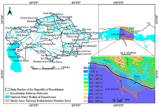
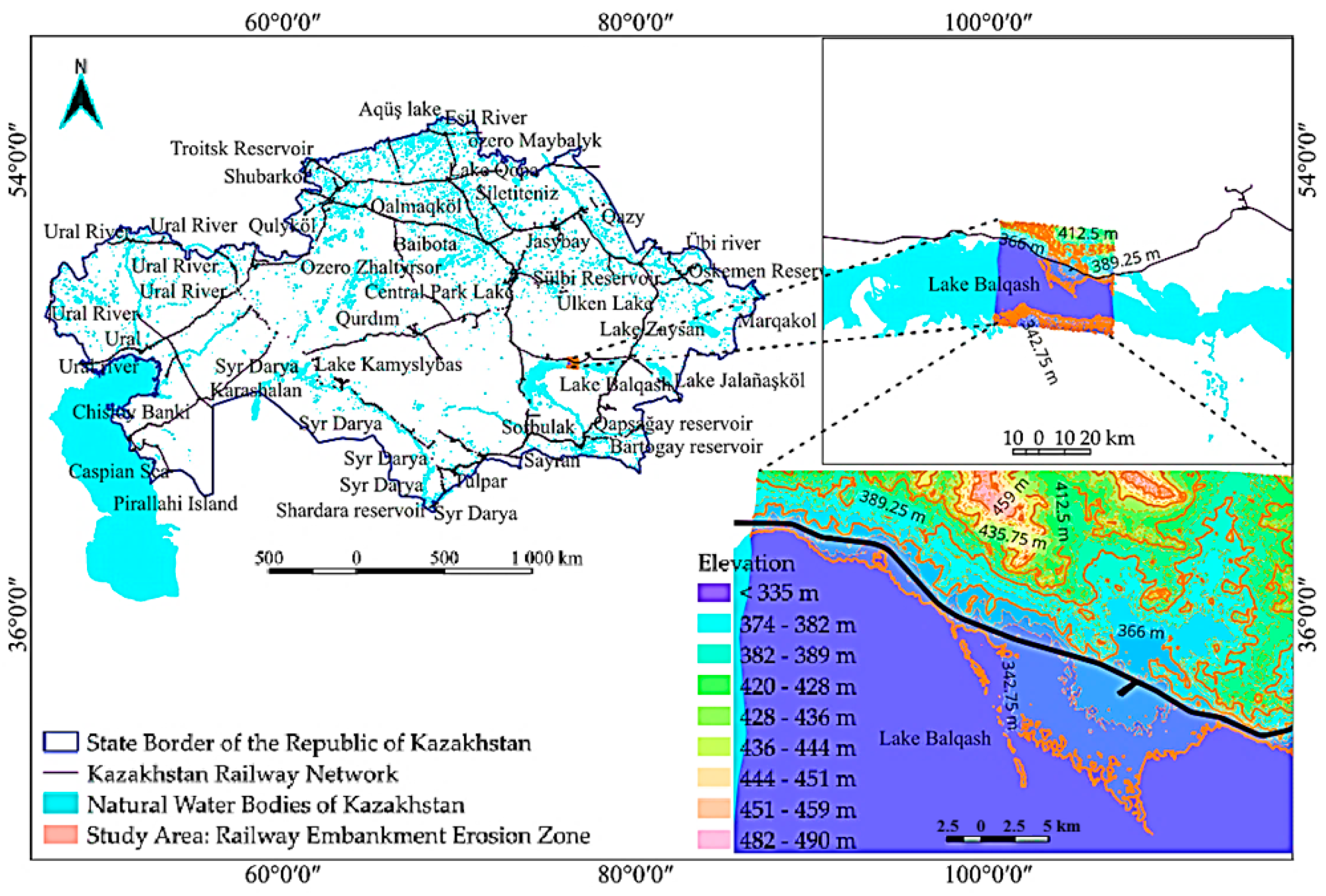
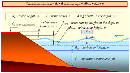
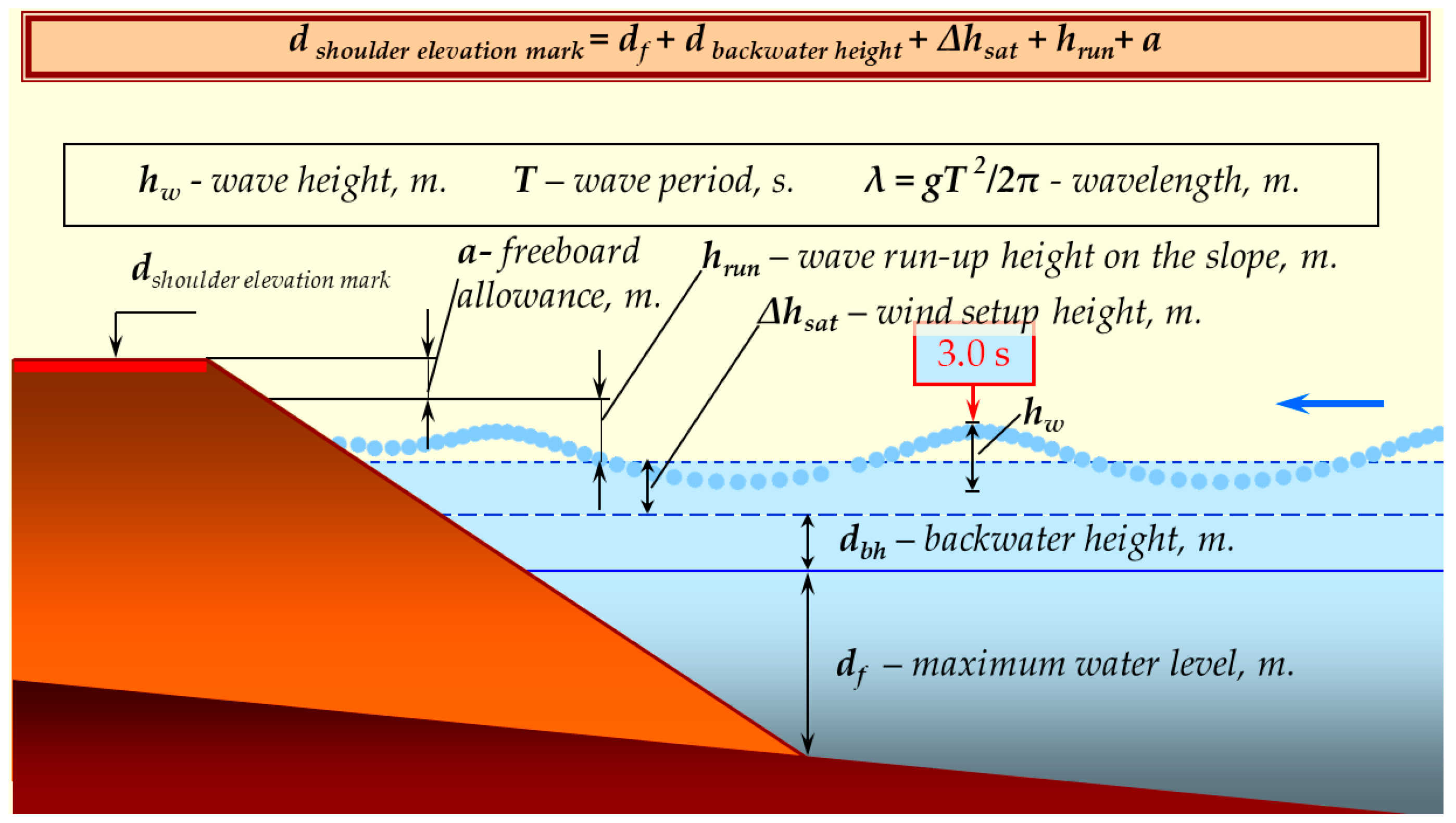
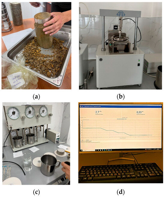
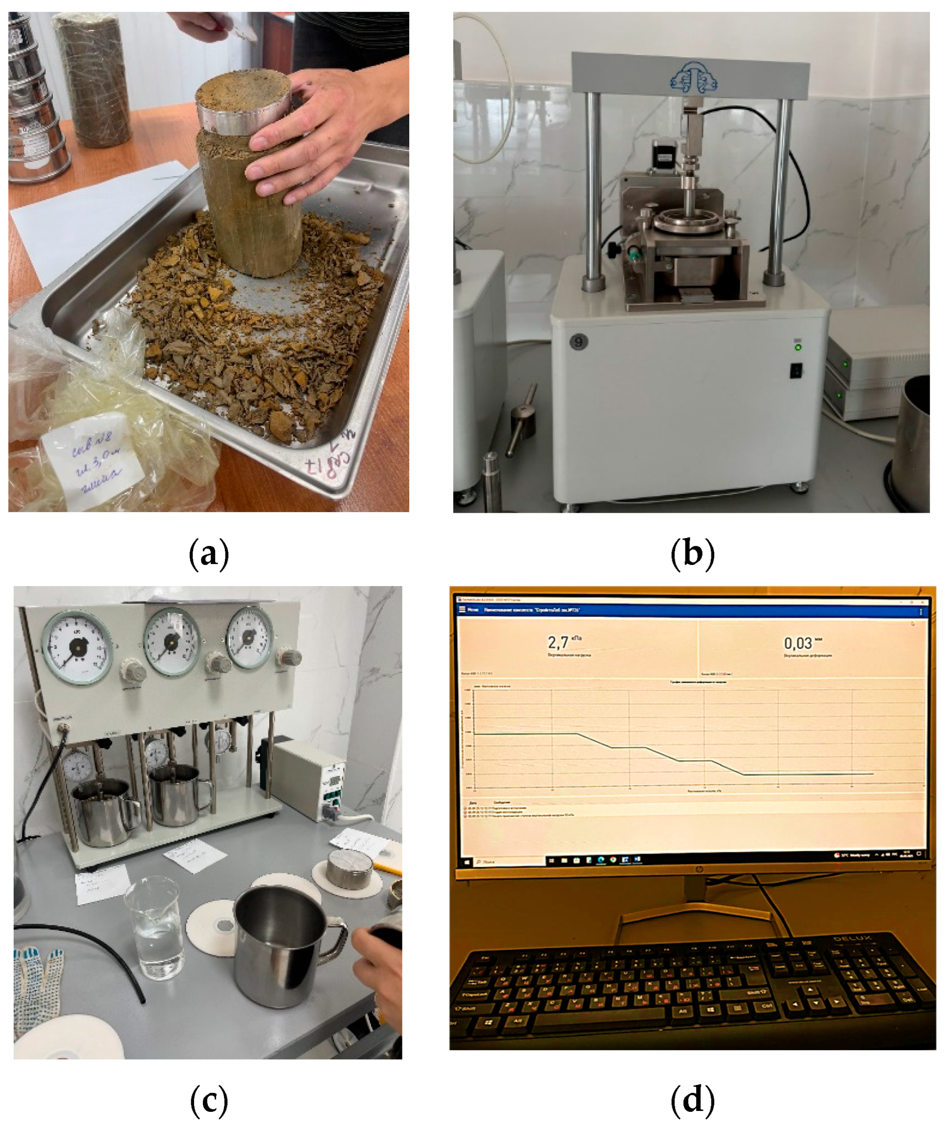
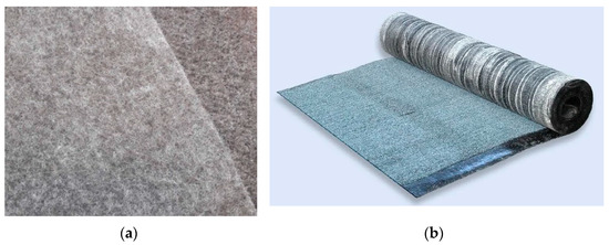
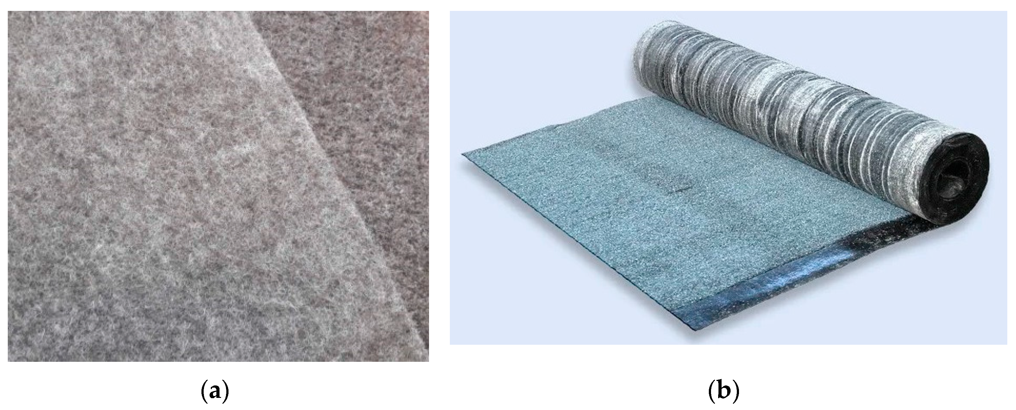
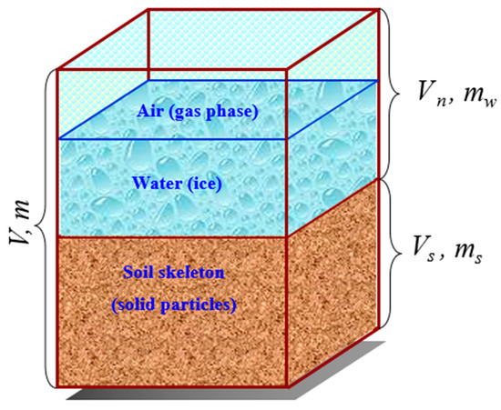
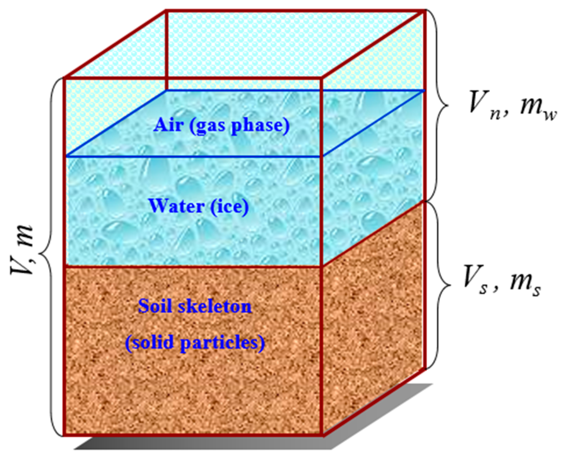
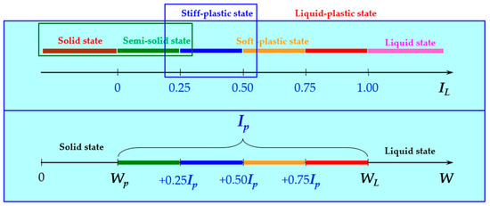
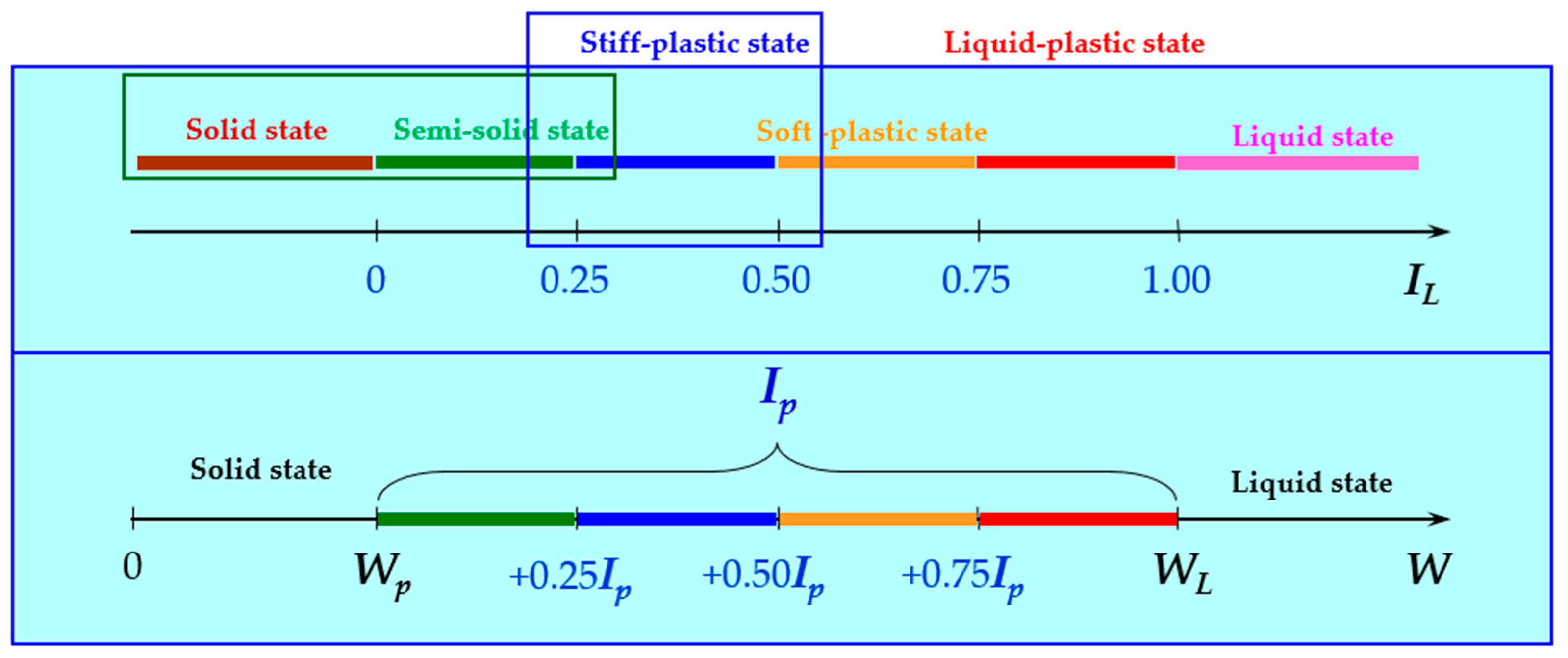
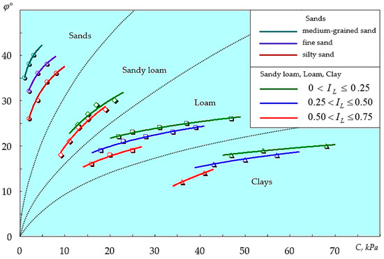
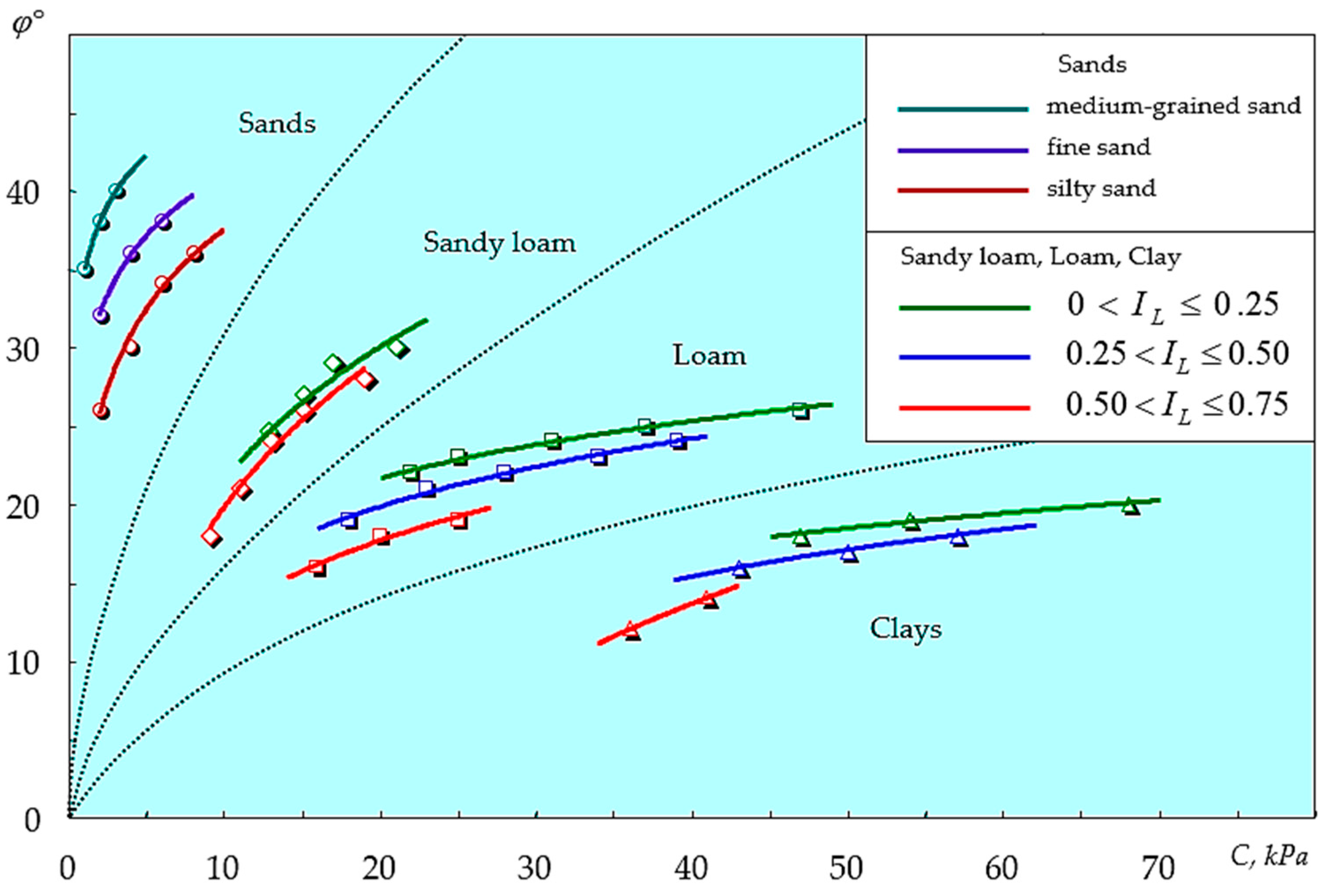
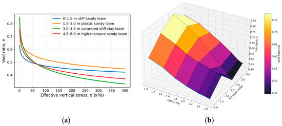
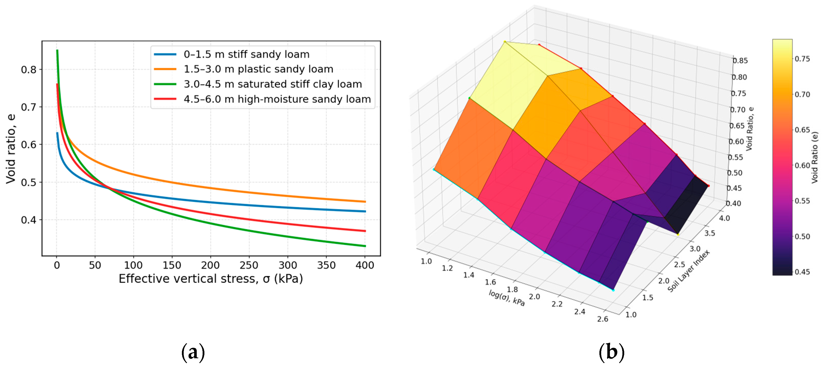
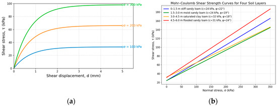
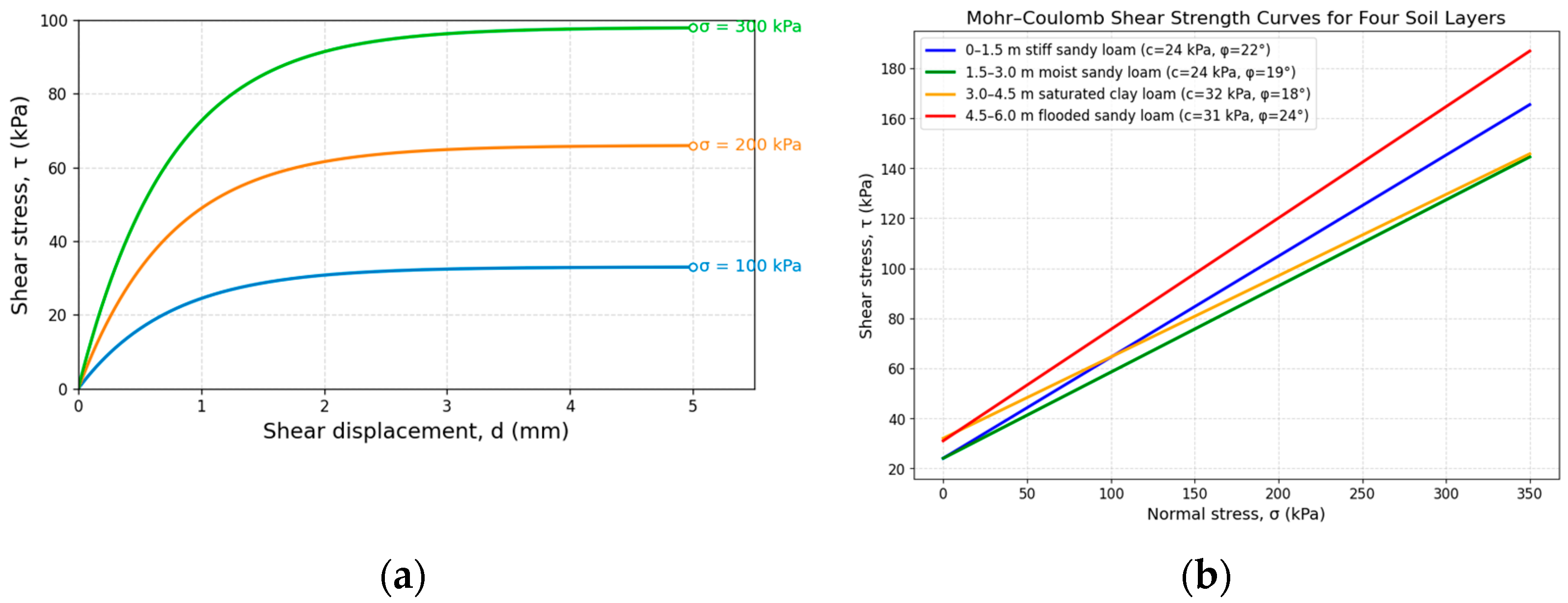
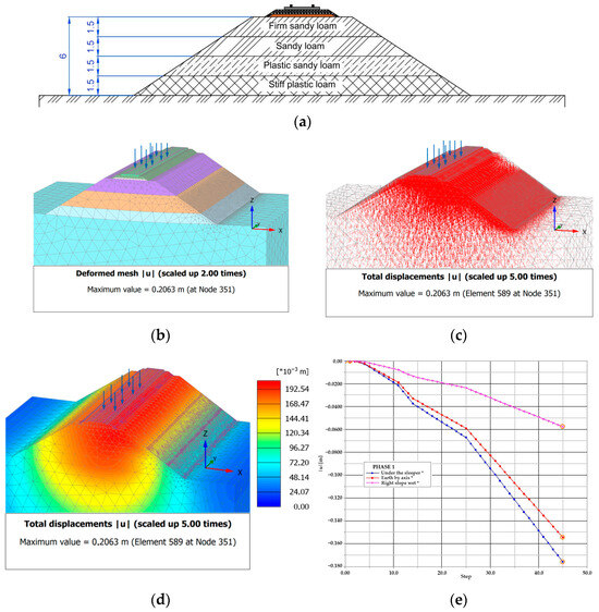
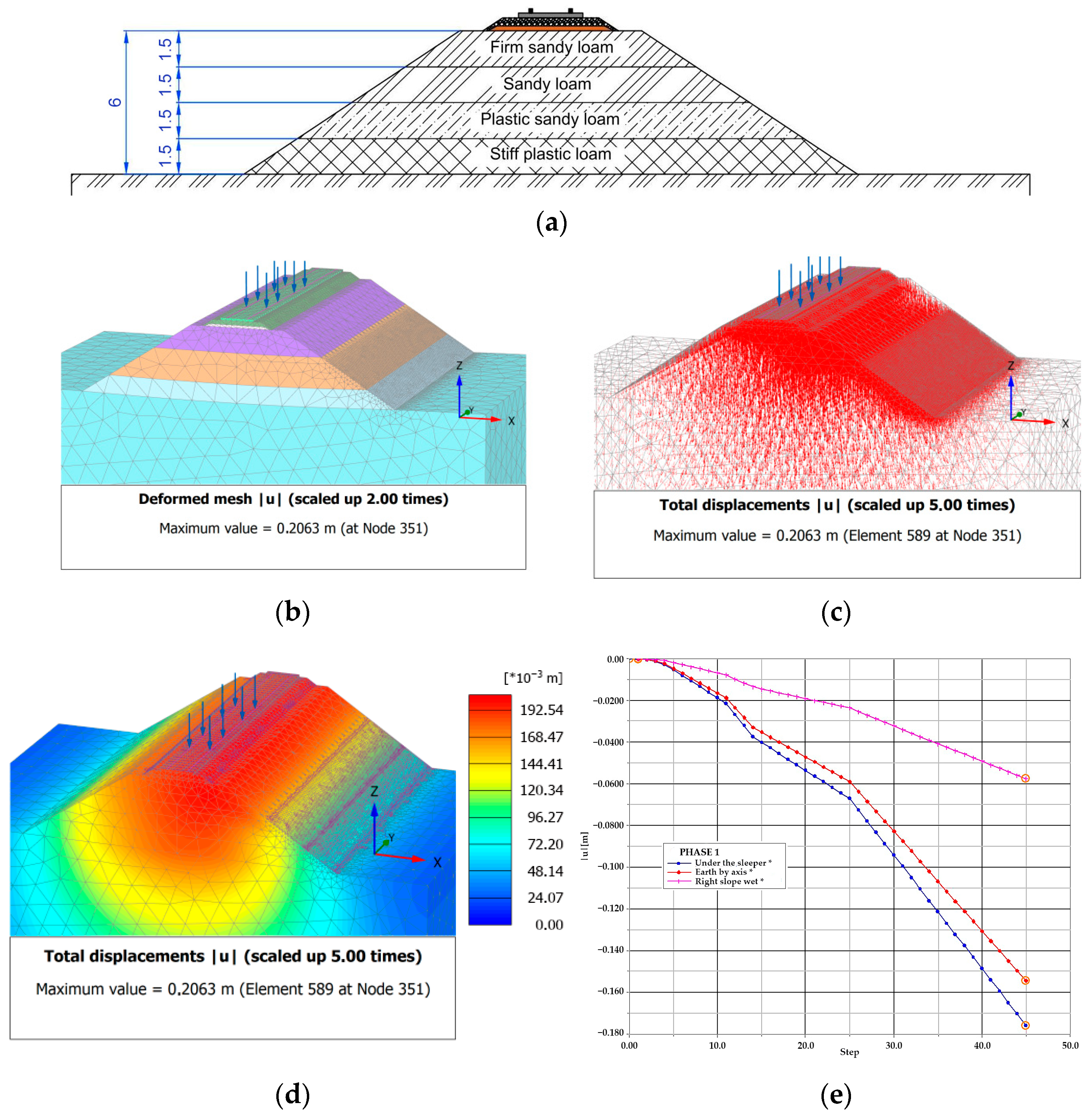
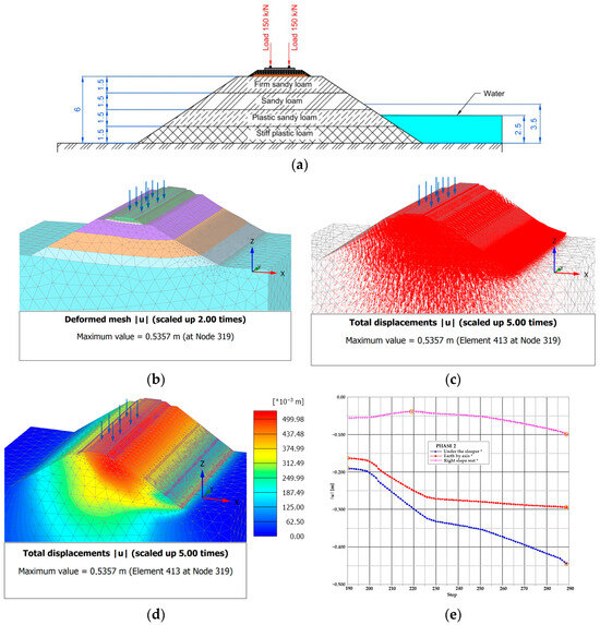
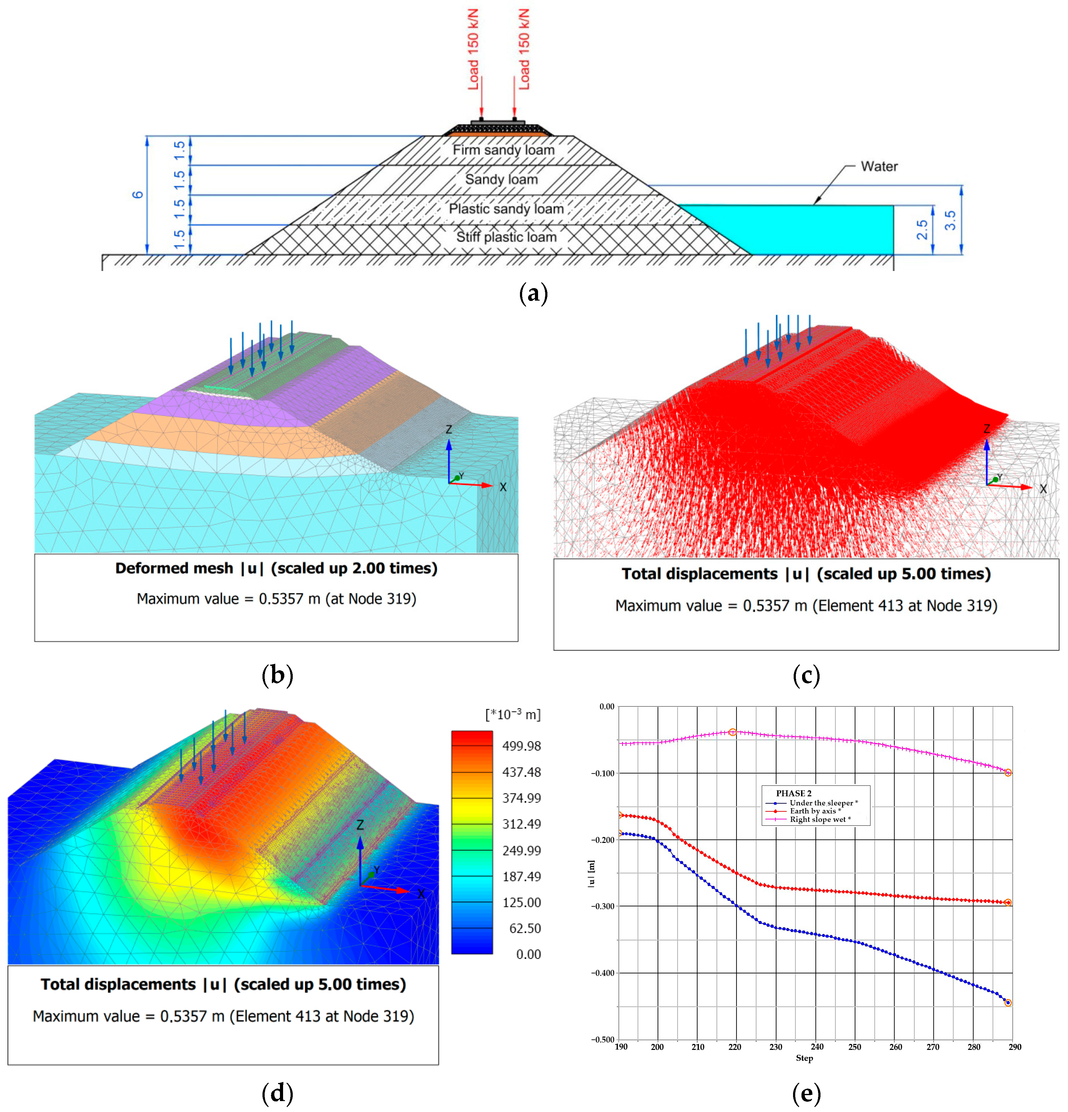
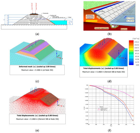
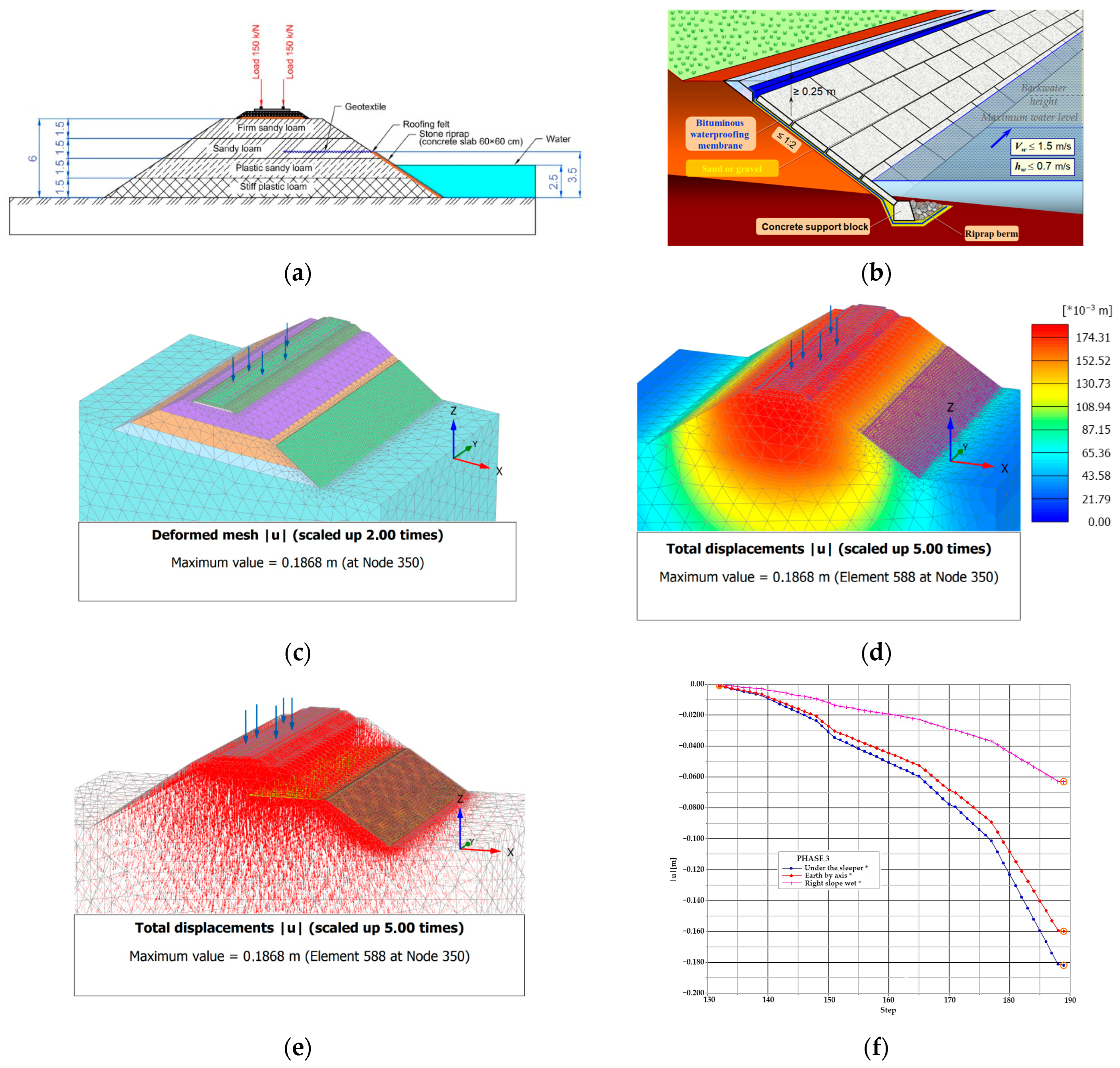
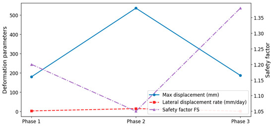

Disclaimer/Publisher’s Note: The statements, opinions and data contained in all publications are solely those of the individual author(s) and contributor(s) and not of MDPI and/or the editor(s). MDPI and/or the editor(s) disclaim responsibility for any injury to people or property resulting from any ideas, methods, instructions or products referred to in the content. |
© 2026 by the authors. Licensee MDPI, Basel, Switzerland. This article is an open access article distributed under the terms and conditions of the Creative Commons Attribution (CC BY) license.