


Abstract
Background/Objectives: Lower-limb impairment can alter ankle-joint motion and reduce functional mobility during demanding locomotor tasks such as stair ascent and descent. This study presents the development and preliminary proof-of-concept evaluation of a BLDC-driven active ankle prosthesis incorporating a spherical gear coupling. Methods: Ankle kinematics were recorded using the CONTEMPLAS motion analysis system for one healthy participant and one participant with impaired lower-limb function during level walking, stair ascent, and stair descent. The resulting ankle-angle trajectories were used as reference profiles for unloaded bench testing of the prototype. Results: Static torque was measured using a handheld dynamometer and a fixed lever arm of 0.10 m. Adjustment of the BLDC controller parameters increased the measured static prototype torque from 0.44 N·m to 6.38 N·m, corresponding to a 14.5-fold increase relative to the initial controller configuration, without modification of the mechanical architecture. Under unloaded fixed-rig conditions, the prototype executed a prescribed cyclic ankle-angle trajectory within a range of 112–132°, corresponding to an amplitude of approximately 20°. The optimized prototype torque remained below the 17.17 N·m obtained from a preliminary static measurement of the healthy participant; however, this value should not be interpreted as a physiological torque requirement for dynamic locomotion. Conclusions: The results demonstrate a substantial control-based increase in the available static actuator output and the ability of the prototype to execute prescribed ankle-angle trajectories under controlled bench conditions. Further validation will require dynamic loading, kinetic measurements, foot–ground interaction, improved control strategies, and human-in-the-loop testing with individuals with lower-limb amputation.
1. Introduction
Lower-limb amputation leads to reduced mobility, altered gait mechanics, and a measurable decline in quality of life [1]. Individuals with transtibial amputation experience the loss of active ankle function, resulting in changes in both spatial and temporal gait characteristics [2]. When passive prosthetic feet are used, load distribution becomes asymmetric, walking speed may decrease, and the absence of active push-off limits the generation of positive mechanical work, thereby increasing compensatory demands on proximal joints [3]. Over time, these compensatory strategies may contribute to secondary musculoskeletal disorders, including chronic lower-back pain and degenerative conditions such as knee osteoarthritis in the intact limb [4,5]. Reduced postural stability and impaired balance control also increase the risk of falls and may further restrict mobility because of fear of falling [6,7]. These challenges are becoming increasingly relevant given the continuing prevalence of lower-limb amputations associated with vascular diseases, including diabetes and peripheral arterial disorders [8,9].
Ankle prostheses are generally classified as passive, semi-active, and powered systems. Passive devices rely on structural geometry, fixed or predefined stiffness, and energy-storage-and-return mechanisms to support locomotion [10,11,12]. Semi-active prostheses incorporate adjustable mechanical elements that modify stiffness, damping, or other properties according to walking conditions [13,14,15,16]. Although these approaches can improve adaptation compared with conventional passive devices, their ability to provide net positive mechanical work remains limited during locomotor tasks requiring increased mechanical output. Powered ankle prostheses address this limitation by using electric actuators to actively generate joint motion and mechanical energy [17,18,19,20]. Such systems can support real-time control and reproduce more complex ankle motion profiles, while phase-based, impedance-based, and related control strategies have been investigated to coordinate prosthetic behavior with different phases of locomotion [21,22,23,24].
The performance requirements of powered ankle prostheses become particularly demanding when locomotion extends beyond level-ground walking. Stair ascent and descent involve different ankle kinematics, loading conditions, and control requirements compared with steady level walking. Previous studies have demonstrated powered prosthetic control during stair locomotion. Lawson et al. [25] developed a control strategy for stair ascent and descent using a powered transfemoral prosthesis, demonstrating the importance of coordinated joint control during transitions between stair phases. Culver et al. [26] subsequently presented a stair ascent and descent controller for a powered ankle prosthesis, further demonstrating the feasibility of active ankle assistance during these demanding locomotor tasks. These studies show that powered prostheses can support stair negotiation; however, actuator output, transmission architecture, and appropriate control remain important factors affecting the ability of a prosthetic ankle to reproduce the required motion under increased mechanical demand.
In parallel with advances in powered prosthesis design, experimental platforms and robotic emulators have been developed to investigate prosthetic behavior and human–prosthesis interaction under controlled and repeatable conditions [27,28,29]. Such platforms are particularly useful during early-stage development because actuator behavior, transmission characteristics, motion trajectories, and control parameters can be evaluated before human-in-the-loop testing. Nevertheless, kinematic behavior obtained from a bench-mounted prototype should not be considered equivalent to human gait under body-weight loading. Human locomotion involves dynamic joint moments, ground reaction forces, neuromuscular activity, and other biomechanical factors that are not reproduced in an unloaded fixed experimental setup. Therefore, controlled bench testing is more appropriately considered an initial proof-of-concept stage for evaluating prosthetic motion and actuator performance prior to comprehensive biomechanical and clinical validation.
The present study investigates a BLDC-driven active ankle prosthesis intended for walking and stair-related locomotion. The novelty of the proposed approach does not lie in the use of a commercially available BLDC motor or a conventional gear-reduction stage alone. Instead, the mechanical contribution is based on the integration of the BLDC actuator and reduction transmission with a spherical gear coupling that transmits actuator torque in the sagittal plane while providing passive adaptability for inversion–eversion in the frontal plane. This configuration separates active plantarflexion–dorsiflexion from passive frontal-plane accommodation without requiring an additional actively controlled actuator. In addition, the available actuator torque is investigated through control-based optimization of the motor-driver parameters rather than being attributed to a newly developed motor or gear-reduction mechanism.
Accordingly, the main contributions of this study are: (1) the integration of a BLDC actuator, reduction transmission, and spherical gear coupling into an active ankle prosthesis architecture providing active sagittal-plane motion and passive frontal-plane adaptability; (2) experimental investigation of control-based actuator torque optimization, including quantitative comparison of prototype torque before and after controller adjustment; and (3) a proof-of-concept kinematic evaluation comparing ankle-angle characteristics recorded during human walking and stair locomotion with those reproduced by the bench-mounted prototype. The resulting analysis is intended to establish an experimental basis for subsequent development toward higher actuator output, dynamic loading experiments, adaptive control, and future human-in-the-loop biomechanical validation.
2. Design and Architecture of the Active Ankle Prosthesis
The developed active ankle prosthesis is designed to reproduce ankle motion while providing a mechanical architecture suitable for controlled torque transmission and future evaluation under increased locomotor demands. The structural concept and basic operating principles of the prosthesis were previously introduced in [30]. In the present study, particular attention is given to the actuator–transmission architecture, the functional role of the spherical gear coupling, and the distinction between mechanical torque transmission and control-based optimization of the available actuator output.
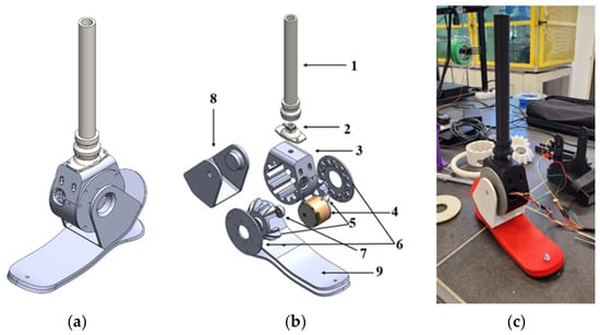
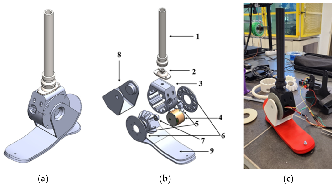
The overall design and fabricated prototype are presented in Figure 1. Figure 1a shows the general CAD model, Figure 1b presents an exploded view of the main mechanical components, and Figure 1c shows the fabricated prototype. The system consists of a foot platform, actuator housing, transmission mechanism, and a vertical attachment structure representing the connection to the shank. A modular configuration was selected to facilitate assembly, component replacement, and iterative modification of the mechanical and actuation elements during prototype development.
Figure 1.
Design and fabricated prototype of the active ankle prosthesis: (a) general CAD model; (b) exploded view showing the main mechanical components; (c) fabricated prototype.
The main components shown in Figure 1b are: (1) load-bearing shaft connected to the shank; (2) upper joint interface; (3) gearbox housing; (4) transmission gear; (5) BLDC motor; (6) spherical gear coupling; (7) intermediate shaft; (8) lateral support plate; and (9) foot segment.
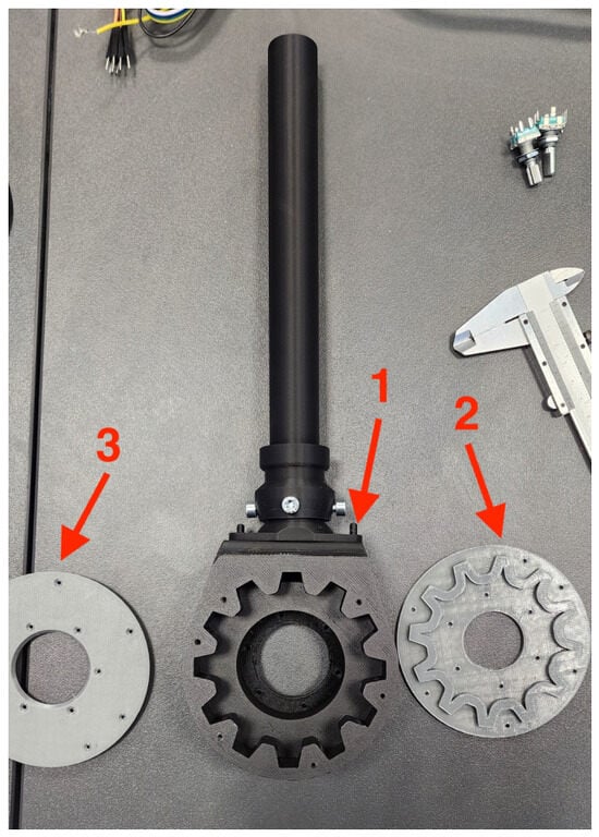
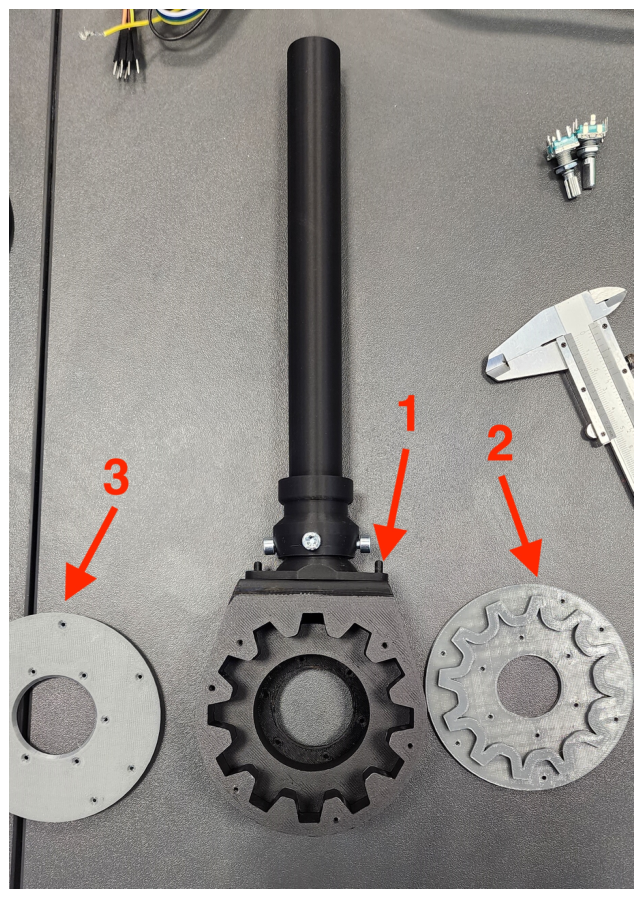
Actuation is provided by a commercially available TS5003-10 brushless DC (BLDC) motor [29] integrated into the central housing. The motor was selected based on its torque density, controllability, compact configuration, and compatibility with closed-loop operation. Motor torque is transmitted through a gear-reduction stage with a transmission ratio of 1:10. The reduction stage provides mechanical torque multiplication before the output is transferred to the ankle mechanism. Structural components of the prototype were manufactured using additive manufacturing, enabling rapid fabrication and iterative modification of the design. The BLDC motor and reduction stage are conventional actuator components and are not considered individually as the novel elements of the proposed design. The specific mechanical feature of the present architecture is its integration with a spherical gear coupling, shown in Figure 2. The coupling consists of an interaction between internal and external gear profiles designed to maintain torque transmission when angular misalignment occurs between the connected elements. In addition to transmitting actuator torque, this arrangement accommodates relative angular displacement without requiring an additional actively controlled actuator for the secondary motion.
Figure 2.
Spherical gear coupling used in the transmission mechanism: (1) input coupling connected to the BLDC motor shaft, (2) external gear element, and (3) cover plate of the coupling assembly.
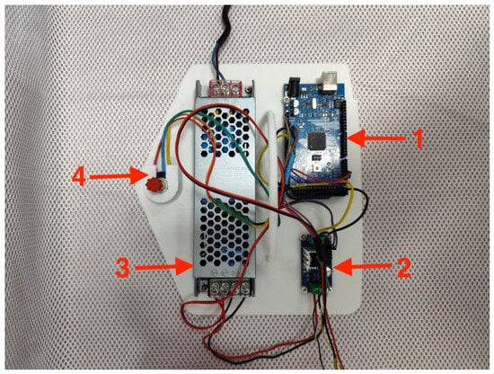
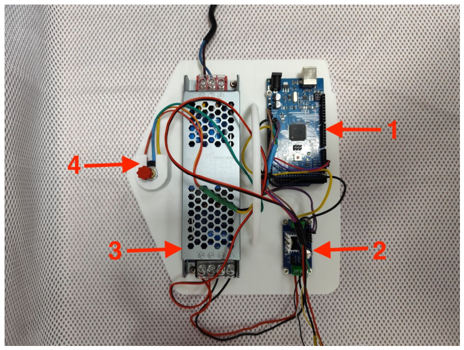
From a functional perspective, the prosthesis incorporates one actively actuated and one passively accommodated rotational motion. Plantarflexion and dorsiflexion in the sagittal plane are actively generated by the BLDC actuator through the 1:10 reduction stage and spherical gear coupling. In contrast, inversion and eversion in the frontal plane are accommodated passively by the angular adaptability of the spherical coupling. This separation of mechanical functions enables active sagittal-plane actuation together with passive frontal-plane adaptability while avoiding the additional actuator and control complexity that would be required for fully active actuation in both planes. The control architecture consists of an Arduino-based control unit, a BLDC motor driver, the TS5003-10 motor, and the mechanical transmission system (Figure 3). The controller provides command signals to the motor driver, which operates the BLDC actuator in closed-loop mode. The resulting motor output is transmitted through the reduction stage and spherical gear coupling to the ankle mechanism. The motor driver allows adjustment of current, torque, and control parameters, which were subsequently used to investigate the available actuator output. The control hardware consists of (1) an Arduino Uno controller, (2) a BLDC motor driver, (3) a DC switching power supply, and (4) an emergency stop (power) switch used to disconnect the electrical supply during experimental testing.
Figure 3.
Control hardware of the active ankle prosthesis: (1) Arduino Uno controller, (2) BLDC motor driver, (3) DC switching power supply, and (4) emergency stop (power) switch.
It is important to distinguish the mechanical function of the transmission architecture from the torque improvement investigated in this study. The 1:10 reduction stage is an inherent component of the mechanical design and provides mechanical torque multiplication according to the selected transmission ratio. In contrast, the experimentally reported increase in prototype torque from its initial operating condition was obtained through control-based optimization of the BLDC motor-driver parameters rather than through a modification of the motor or the mechanical reduction mechanism. Therefore, the torque enhancement reported in this work should be interpreted as an increase in the available actuator output achieved through controller adjustment within the existing mechanical architecture. The corresponding control parameters, measurement procedure, and quantitative torque results are described separately in Section 5. Accordingly, the engineering contribution of the proposed design is not the use of a commercial BLDC motor or a conventional gear-reduction stage alone, but the integrated actuator–transmission architecture in which the BLDC drive and reduction mechanism operate together with a spherical gear coupling to provide active plantarflexion–dorsiflexion and passive inversion–eversion. This architecture establishes a compact proof-of-concept platform for investigating ankle motion, actuator torque capability, and subsequent control development. Further evaluation under external loading and human–prosthesis interaction will be required to determine its performance under actual locomotor conditions.
3. Experimental Setup and Measurement Methodology
The experimental study was designed as an initial proof-of-concept investigation to obtain quantitative ankle-joint kinematic data during human locomotion and to use these data as reference motion profiles for subsequent bench testing of the developed prosthesis. The study focused on ankle-angle trajectories during level walking, stair ascent, and stair descent. Accordingly, the experimental evaluation presented in this work should be interpreted as a preliminary kinematic assessment rather than a comprehensive biomechanical validation involving joint kinetics, ground reaction forces, electromyography, or metabolic measurements.
3.1. Participants and Human Motion Capture
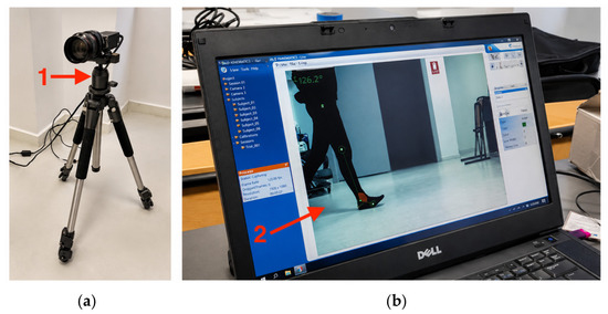
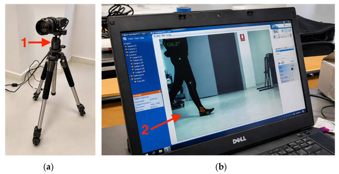
Two participants were included in the preliminary kinematic study. The impaired participant was 45 years old, had a shoe size of 43, and had a diagnosed lumbar intervertebral disc herniation at the L5–L6 level. The healthy participant was 29 years old, had a shoe size of 42, and had no reported lower-limb functional impairment. Neither participant had a lower-limb amputation. Because the present investigation involved only two participants, the human-motion measurements were intended to provide representative reference trajectories for proof-of-concept evaluation rather than population-level biomechanical conclusions or statistical comparisons. Human-motion data were acquired using the CONTEMPLAS motion analysis system [30], consisting of a high-resolution camera and dedicated software for kinematic processing (Figure 4). The camera was mounted on a tripod and positioned approximately perpendicular to the sagittal plane of motion to minimize projection-related errors during ankle-angle measurement. Before each recording session, the measurement area was calibrated, and the camera focus and lighting conditions were adjusted to maintain consistent visualization of the markers. The CONTEMPLAS motion-analysis system consists of (a) a high-resolution camera used for sagittal-plane motion capture and (b) the CONTEMPLAS software (Version 3.10) interface used for real-time visualization, tracking, and processing of ankle-joint kinematics.
Figure 4.
CONTEMPLAS motion analysis system used for kinematic data acquisition: (a) experimental camera setup and sagittal-plane recording area; (b) software interface used for marker tracking and ankle-angle analysis.
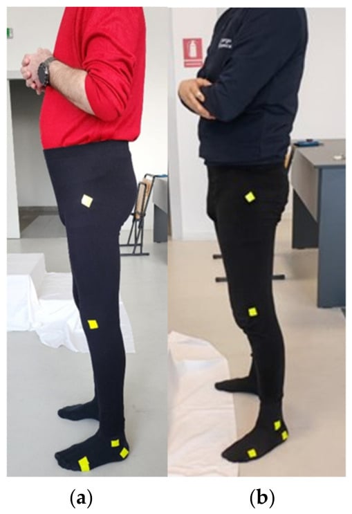
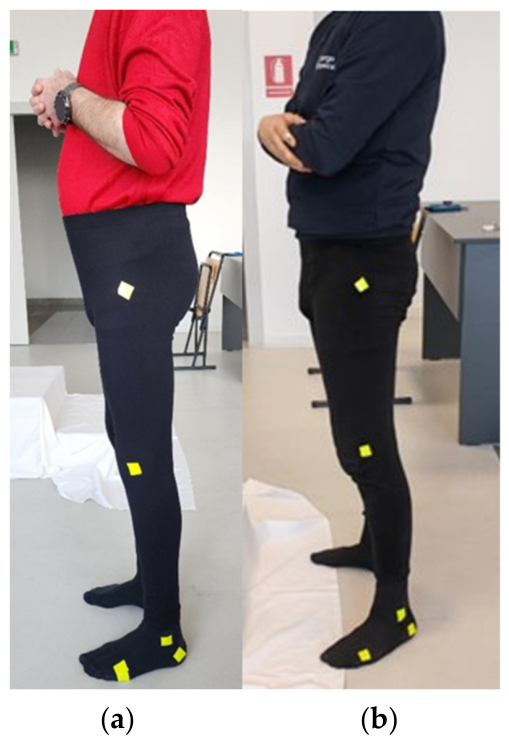
Reflective markers were positioned on the foot, ankle region, and shank at predefined anatomical landmarks to enable sagittal-plane motion tracking. Figure 5 shows the marker configurations used for (a) the impaired participant and (b) the healthy participant. Identical marker placement and the same motion-analysis protocol were applied to both participants to ensure consistent estimation of ankle-joint angles throughout the experiments.
Figure 5.
Marker placement for sagittal-plane ankle-motion analysis: (a) impaired participant; (b) healthy participant.
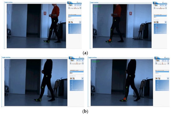
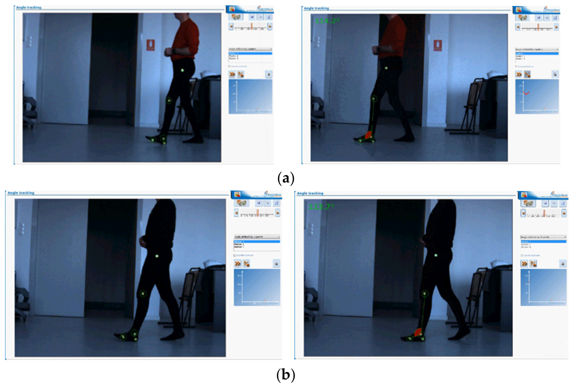
The experimental protocol included three locomotor conditions: level walking, stair ascent, and stair descent. During each condition, motion was recorded in real time and subsequently processed using the CONTEMPLAS software. Representative recordings of level walking for the impaired and healthy participants are shown in Figure 6.
Figure 6.
Representative CONTEMPLAS recordings during level walking: (a) impaired participant; (b) healthy participant.
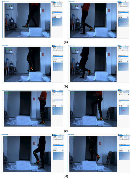
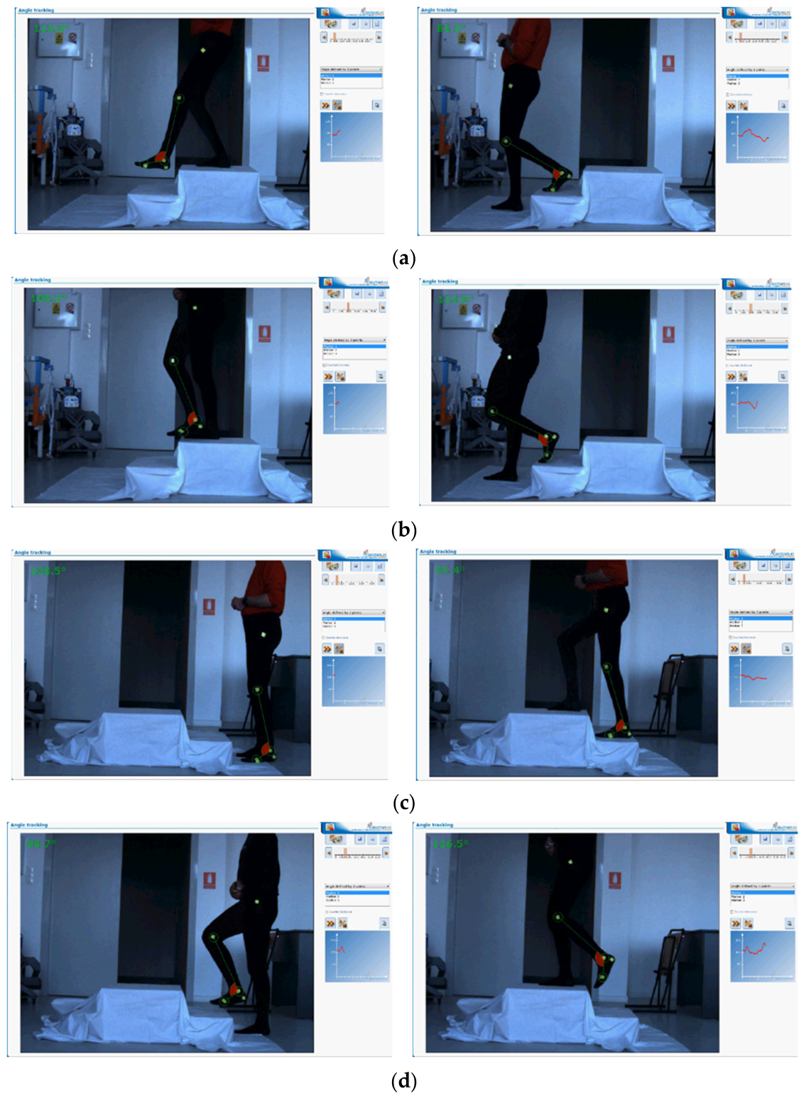
Stair ascent and descent were performed using the same step platform for both participants. These measurements were intended to characterize differences in ankle-angle patterns between the two participants under a locomotor task requiring a larger range of ankle motion than level walking. Representative recordings of the stair trials are presented in Figure 7.
Figure 7.
Human stair-locomotion experiments: (a) impaired participant during stair descent; (b) healthy participant during stair descent; (c) impaired participant during stair ascent; (d) healthy participant during stair ascent.
The recorded marker trajectories were processed to obtain ankle-angle functions, θ(t). For comparison between locomotor trials, each trajectory was normalized to a gait cycle ranging from 0% to 100%. The resulting angular profiles were subsequently used as kinematic reference trajectories for evaluating the motion of the prosthesis prototype. Because of the limited number of participants, no population-level statistical inference was performed, and the measured trajectories were used only for the preliminary proof-of-concept comparison described in this study.
3.2. Bench-Mounted Prototype Testing
Prototype testing was conducted separately from the human-motion experiments using a fixed experimental rig. The purpose of this stage was to evaluate the ability of the developed prosthesis to execute prescribed ankle-angle trajectories under controlled and repeatable bench conditions before progressing to human-in-the-loop testing.
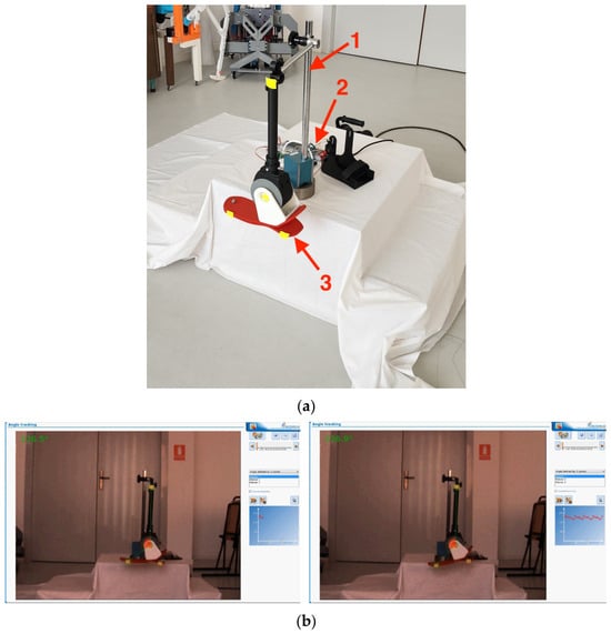
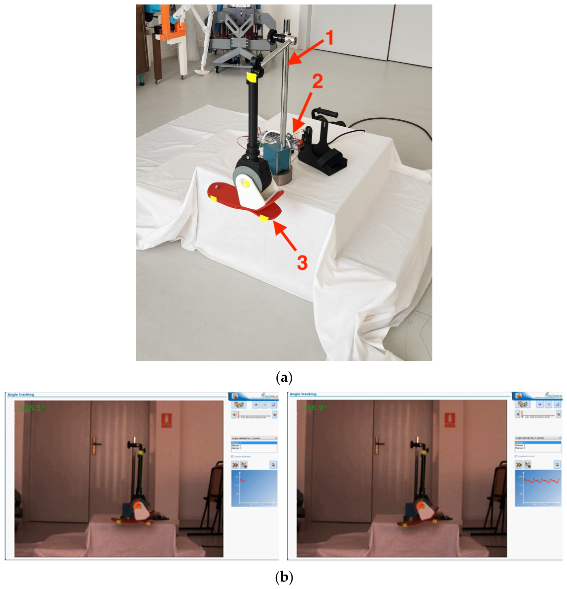
The prosthesis was mounted on a stationary support and connected to the control system. Figure 8a shows the fixed experimental configuration, consisting of (1) the prototype support frame, (2) the electronic control unit, and (3) the active ankle prosthesis prototype. The system was operated in automatic mode using predefined angular trajectories derived from the human-motion measurements. Figure 8b presents representative prototype motion during execution of the prescribed ankle-angle trajectory.
Figure 8.
Bench-mounted proof-of-concept testing of the active ankle prosthesis: (a) fixed experimental configuration showing (1) the prototype support frame, (2) the electronic control unit, and (3) the active ankle prosthesis prototype; (b) representative prototype motion during execution of a prescribed ankle-angle trajectory.
Importantly, the bench-mounted prototype experiments were not mechanically equivalent to the human stair-locomotion trials. During prototype testing, the prosthetic foot did not physically contact the stair surface, and the device was not subjected to body-weight loading, ground reaction forces, or direct human–prosthesis interaction. Therefore, the prototype experiments were not intended to reproduce the complete biomechanical conditions of stair ascent or descent. Instead, the human measurements provided reference ankle-angle trajectories, while the fixed-rig experiments were used to determine whether the prototype could reproduce the prescribed kinematic patterns under unloaded bench conditions.
Testing the prosthesis directly with individuals with lower-limb amputation was beyond the scope of this initial proof-of-concept stage. Such human-in-the-loop evaluation represents a subsequent phase of development and requires a dedicated experimental protocol, appropriate safety assessment, and corresponding ethical approval before the device can be evaluated under body-weight loading and actual locomotor conditions.
3.3. Scope of the Experimental Comparison
The human and prototype experiments were intentionally conducted under different mechanical conditions and should therefore not be interpreted as a direct biomechanical comparison. Human measurements were obtained during actual level walking and stair locomotion, whereas prototype measurements were obtained from a stationary, unloaded experimental configuration. The comparison performed in this study is consequently limited to ankle-angle characteristics and the ability of the prototype to reproduce prescribed reference trajectories.
This experimental framework provides an initial assessment of the kinematic behavior and controllability of the developed prototype but does not constitute comprehensive biomechanical or clinical validation. Further studies will require dynamic loading, physical foot–ground and foot–stair interaction, measurements of kinetic variables, and human-in-the-loop experiments with an appropriately sized participant cohort before conclusions regarding functional prosthetic performance during actual locomotion can be established.
4. Kinematic Analysis of Human Ankle Motion and Prototype Response
This section presents a descriptive kinematic analysis of ankle-angle trajectories obtained from the two participants using the CONTEMPLAS motion analysis system. The analysis focuses on the angular range, amplitude, and temporal characteristics of ankle motion during level walking, stair descent, and stair ascent. Because the study included only one healthy participant and one participant with impaired lower-limb function, the results are interpreted as preliminary proof-of-concept observations and are not intended to support population-level statistical conclusions.
The prototype results are also presented in this section for descriptive kinematic comparison. However, as described in Section 3, the human and prototype experiments were performed under different mechanical conditions. Human measurements were obtained during actual locomotion under body-weight loading and foot–ground or foot–stair interaction, whereas the prototype was evaluated on a fixed experimental rig without body-weight loading or physical contact with a stair surface. Therefore, comparisons between the human and prototype trajectories are limited to angular characteristics and should not be interpreted as evidence of equivalent biomechanical or functional performance.
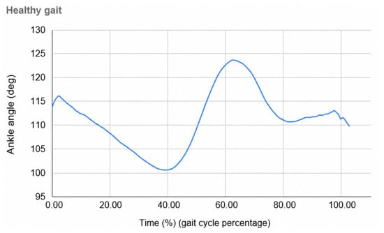
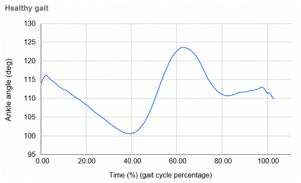
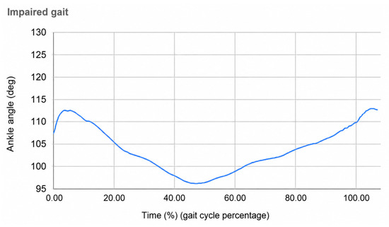
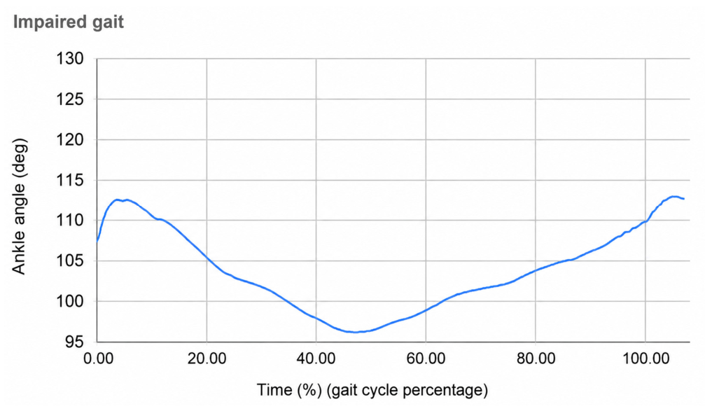
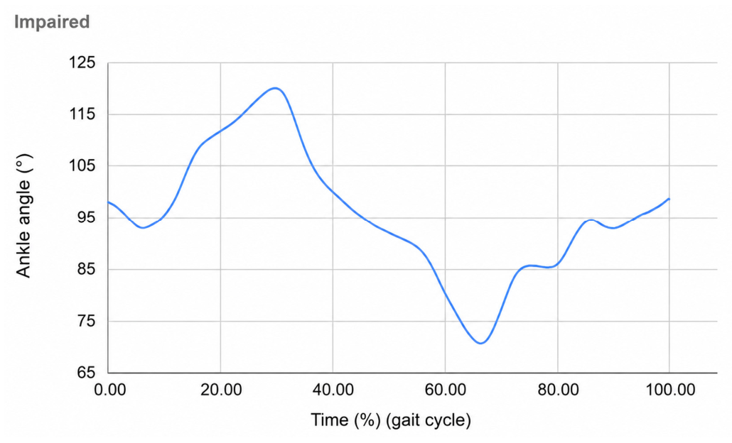
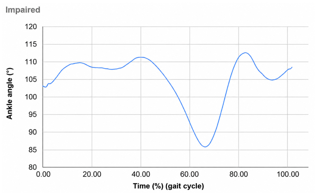
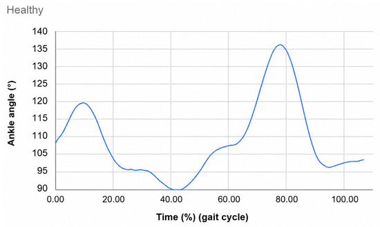
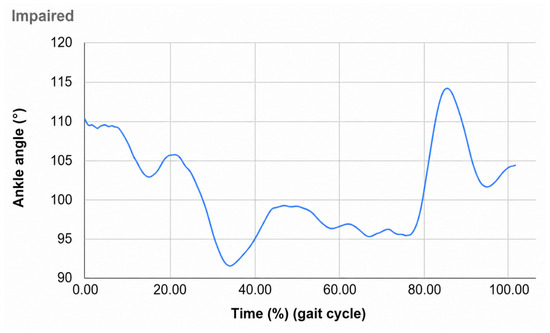
The ankle-angle trajectories, θ(t), were normalized over the gait cycle from 0% to 100% and are presented individually in Figure 9, Figure 10, Figure 11, Figure 12, Figure 13, Figure 14 and Figure 15.
Figure 9.
Ankle-angle trajectory during level walking for the healthy participant.
Figure 10.
Ankle-angle trajectory during level walking for the impaired participant.
Figure 11.
Ankle-angle trajectory during stair descent for the healthy participant.
Figure 12.
Ankle-angle trajectory during stair descent for the impaired participant.
Figure 13.
Ankle-angle trajectory during stair ascent for the healthy participant.
Figure 14.
Ankle-angle trajectory during stair ascent for the impaired participant.
Figure 15.
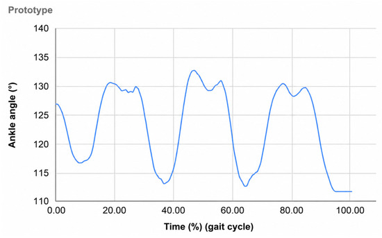
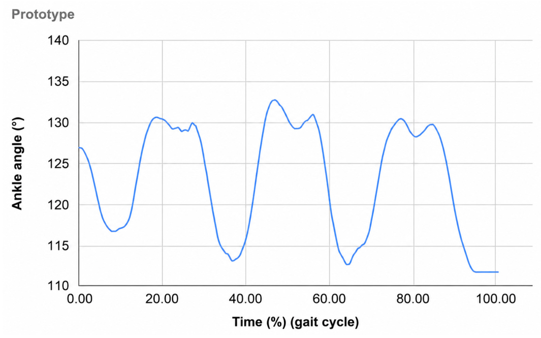
Ankle-angle trajectory reproduced by the prototype during unloaded bench testing.
During level walking, the healthy participant exhibited an ankle-angle range of approximately 100° to 123°, corresponding to an angular amplitude of approximately 23° (Figure 9). The maximum angle occurred at approximately 60–65% of the normalized gait cycle, while the minimum value was observed near 40% of the cycle. This pattern represents the measured sagittal-plane ankle motion of the healthy participant during the recorded walking trial.
The impaired participant exhibited a smaller ankle-angle range during level walking, extending from approximately 97° to 112°, with an angular amplitude of approximately 15° (Figure 10). Compared with the healthy participant, the measured angular amplitude was approximately 35% lower. The trajectory also showed a smaller angular excursion and less pronounced variation over the normalized gait cycle.
During stair descent, the healthy participant exhibited an ankle-angle range of approximately 95° to 120°, corresponding to an angular amplitude of approximately 25° (Figure 11). The trajectory remained continuous throughout the normalized cycle, with gradual changes in ankle angle during the recorded stair-descent trial.
For the impaired participant, the stair-descent trajectory extended from approximately 85° to 112° (Figure 12). The principal angular excursion was approximately 20°, while a transient decrease to approximately 85° was observed during the recorded cycle. Compared with the healthy participant, the trajectory exhibited a different angular pattern and a more pronounced local decrease in ankle angle.
During stair ascent, the healthy participant demonstrated the largest ankle-angle excursion among the three recorded locomotor conditions. The measured angle ranged from approximately 93° to 135°, corresponding to an amplitude of approximately 42° (Figure 13). A pronounced angular maximum occurred at approximately 70–75% of the normalized cycle. This observation indicates a larger sagittal-plane ankle excursion during the recorded stair-ascent trial than during level walking or stair descent for the same participant.
The impaired participant exhibited an ankle-angle range of approximately 92° to 114° during stair ascent, corresponding to an amplitude of approximately 22° (Figure 14). The angular maximum was lower and occurred at a different position within the normalized cycle compared with the healthy participant. These results indicate a different ankle-motion pattern and a smaller sagittal-plane angular excursion during the recorded stair-ascent trial. Because joint moments, ground reaction forces, and muscle activity were not measured in the present experiment, the observed kinematic differences alone should not be interpreted as direct evidence of reduced ankle torque generation.
The ankle-angle trajectory reproduced by the prototype during unloaded bench testing is shown in Figure 15. The measured angular range extended from approximately 112° to 132°, corresponding to an amplitude of approximately 20°. The trajectory exhibited a periodic pattern, with angular maxima occurring at approximately 45–55% and 75–85% of the normalized cycle. High-frequency oscillations were also observed, particularly during transitions between portions of the prescribed trajectory.
The prototype trajectory was shifted toward higher absolute angular values by approximately 10–15° compared with the human level-walking trajectories. Its angular amplitude of approximately 20° was greater than the approximately 15° observed for the impaired participant during level walking but lower than the approximately 23° observed for the healthy participant. However, these numerical differences should be interpreted only as a descriptive comparison of angular trajectories. The prototype was not subjected to body-weight loading, dynamic ground reaction forces, biological damping, or direct foot–ground interaction during these measurements.
The oscillatory behavior observed in the prototype trajectory may be associated with actuator dynamics, controller settings, transmission characteristics, and the absence of the passive biological damping present in the human musculoskeletal system. Nevertheless, the present measurements do not allow the individual contribution of these factors to be quantified. Further dynamic experiments under controlled external loading would be required to determine their effects on prosthetic motion.
A quantitative summary of the measured angular characteristics is provided in Table 1. Prototype values are reported separately from the stair-locomotion measurements because the prototype did not perform physical stair ascent or descent during the bench experiment.
Table 1.
Descriptive comparison of measured ankle-angle characteristics.
Overall, the participant measurements demonstrate distinct ankle-angle characteristics across the three recorded locomotor conditions, with the largest angular excursion observed during stair ascent in the healthy participant. The impaired participant exhibited smaller angular excursions during level walking and stair ascent in the recorded trials. The prototype was able to execute a prescribed cyclic ankle-angle trajectory within an approximately 20° range under fixed-rig conditions, although oscillations and an offset in absolute angular position were observed.
These findings should be interpreted as a preliminary kinematic assessment rather than comprehensive biomechanical validation. In particular, the prototype trajectory does not demonstrate reproduction of physiological push-off or equivalence to healthy gait because the bench experiment did not include body-weight loading, foot–ground interaction, joint-moment measurements, or other kinetic and neuromuscular variables. The present results therefore provide a proof-of-concept basis for subsequent experiments incorporating external loading, kinetic measurements, and human-in-the-loop evaluation.
5. Static Torque Measurement and Control-Based Optimization of the Prototype
The torque evaluation was performed as a preliminary static experiment to quantify the available output torque of the prototype and to investigate the effect of BLDC controller adjustment on actuator performance. In addition, a static ankle-torque measurement was obtained from the healthy participant to provide an experimental reference under the specific measurement conditions used in this study. These measurements were not intended to represent dynamic ankle-joint moments during walking or stair locomotion.
5.1. Static Torque Measurement Method
A handheld dynamometer and a cable-based lever arrangement were used for the static force measurements. The force was applied through a cable at a defined distance from the ankle rotation axis. The lever arm was maintained at for both the human and prototype measurements. The dynamometer reading was converted into force according to
where is the applied force in newtons, is the equivalent mass indicated by the dynamometer in kilograms, and is gravitational acceleration.
The corresponding static torque was calculated as
where is the calculated torque in N·m and is the perpendicular distance between the ankle rotation axis and the point of force application. Accordingly, the torque can also be expressed as
This force-based approach provides a simple method for estimating static joint or actuator torque from a single-axis force measurement and a known moment arm [31,32]. The same lever-arm value and calculation procedure were used for the preliminary human measurement and for the prototype measurements before and after controller optimization.
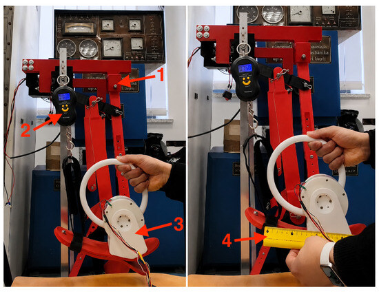
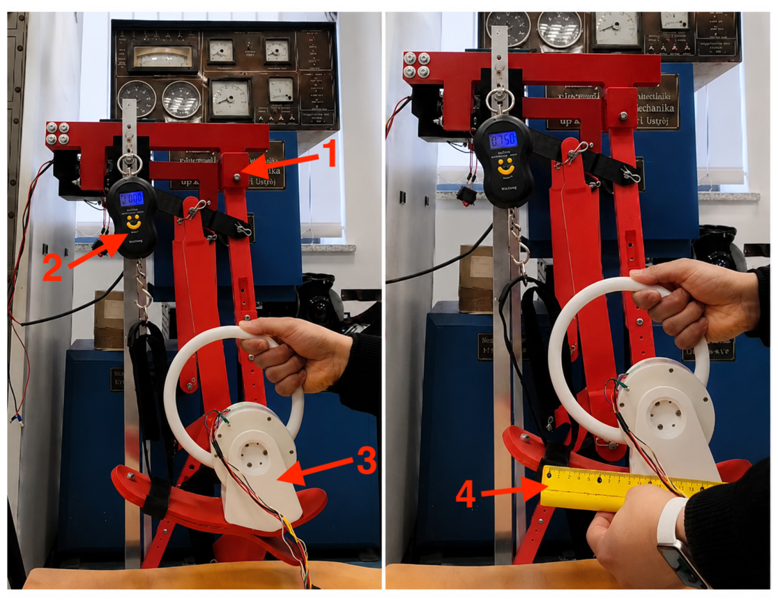
The initial prototype measurement configuration is shown in Figure 16. The prototype was mounted on the experimental support to limit movement of the assembly during force application. The force was applied through the cable at the specified 0.10 m lever arm from the rotation axis.
Figure 16.
Initial static torque measurement of the prototype: (1) prototype support frame, (2) handheld dynamometer used for force measurement, (3) active ankle prosthesis prototype, and (4) ruler indicating the 0.10 m lever arm used for torque calculation.
5.2. Preliminary Static Human Ankle-Torque Measurement
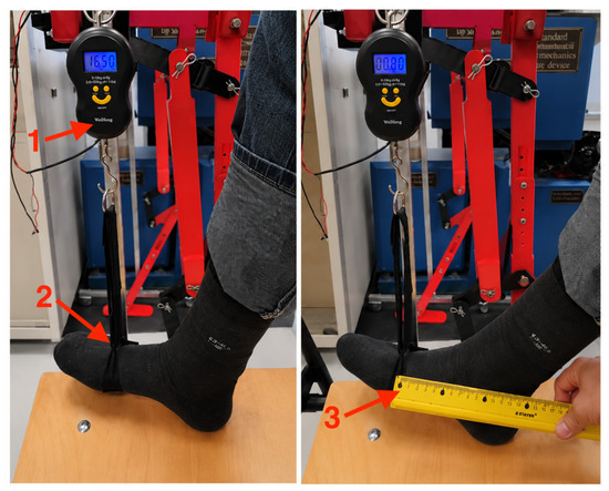
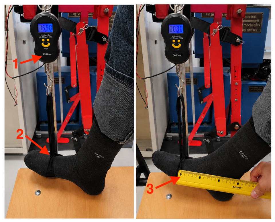
Figure 17 illustrates the experimental arrangement used for the preliminary static ankle-torque measurement, consisting of (1) a handheld dynamometer, (2) the healthy participant’s foot positioned for static force application, and (3) a ruler indicating the predefined 0.10 m lever arm used in the torque calculation.
Figure 17.
Preliminary static measurement of the healthy participant’s ankle torque: (1) handheld dynamometer, (2) healthy participant’s foot positioned for static force application, and (3) ruler indicating the 0.10 m lever arm used for torque calculation.
The dynamometer indicated an equivalent mass of 17.5 kg. Using Equation (1), the corresponding force was
For the defined lever arm of 0.10 m, the calculated static torque was
5.3. Initial Prototype Torque
Before controller optimization, the prototype was evaluated using the same 0.10 m lever arm. The dynamometer indicated an equivalent mass of approximately 0.45 kg, corresponding to
The resulting static output torque was therefore
The relatively low initial output was observed with the original BLDC controller configuration, in which the available actuator output was constrained by the motor-driver control settings. This measurement was therefore considered the baseline condition for evaluating the subsequent control-based optimization.
5.4. Control-Based Optimization of the BLDC Actuator
The optimization procedure was performed through adjustment of the BLDC motor-controller parameters. The mechanical configuration of the prototype, including the TS5003-10 BLDC motor, 1:10 reduction stage, spherical gear coupling, and other transmission components, remained unchanged throughout this procedure.
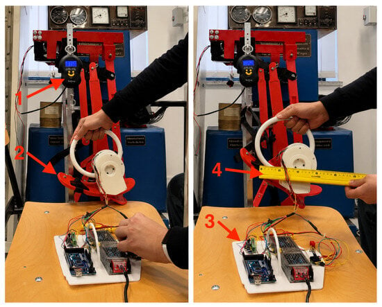
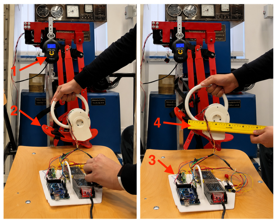
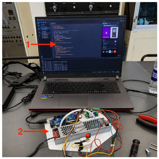
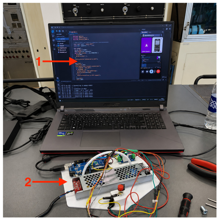
The controller settings governing the available motor current and torque output were adjusted, and the controller was tuned for operation in torque-control mode. In particular, the restrictive settings of the initial controller configuration were modified to increase the available actuator output while maintaining the same mechanical transmission architecture. Figure 18 illustrates the experimental configuration used during this procedure, consisting of (1) a handheld dynamometer, (2) the active ankle prosthesis prototype, (3) the electronic control unit, and (4) a ruler indicating the predefined 0.10 m lever arm used for torque calculation. The BLDC control interface used during this procedure is shown in Figure 18.
Figure 18.
BLDC controller optimization before the final static torque measurement: (1) handheld dynamometer, (2) active ankle prosthesis prototype, (3) electronic control unit, and (4) ruler indicating the predefined 0.10 m lever arm used for torque calculation.
It is important to distinguish this procedure from mechanical torque enhancement. No structural modification of the motor, gearbox, spherical gear coupling, or transmission ratio was introduced between the initial and optimized measurements. Therefore, the increase reported in this study represents a control-based increase in the available output torque of the existing actuator–transmission system rather than torque enhancement resulting from structural redesign.
5.5. Prototype Torque After Control Optimization
After adjustment of the BLDC controller, the static torque measurement was repeated using the same experimental arrangement and the same 0.10 m lever arm. Figure 19 shows the BLDC controller optimization system, consisting of (1) the controller software interface and (2) the electronic control unit used for parameter adjustment prior to the final static torque measurement. After completion of the controller tuning, the dynamometer indicated an equivalent mass of approximately 6.5 kg. The corresponding force was:
Figure 19.
BLDC controller optimization system: (1) BLDC controller software interface used to modify the control parameters and (2) electronic control unit consisting of the Arduino controller, BLDC motor driver, and power supply.
The resulting static output torque was
The measured prototype torque therefore increased from approximately 0.44 N·m in the initial controller configuration to approximately 6.38 N·m after controller optimization. This corresponds to an approximately 14.5-fold increase relative to the initial condition:
A summary of the static measurements is provided in Table 2.
Table 2.
Summary of preliminary static torque measurements.
The optimized prototype output remained below the 17.17 N·m value obtained during the preliminary static measurement of the healthy participant. However, because these values were obtained under simplified static experimental conditions, their difference should not be interpreted directly as a measure of functional performance during locomotion.
The present results demonstrate that adjustment of the BLDC controller substantially increased the available static output torque of the existing prototype without modification of its mechanical architecture. Specifically, the measured output increased from 0.44 N·m to 6.38 N·m, corresponding to a 14.5-fold increase relative to the initial controller configuration. This result demonstrates the effect of controller settings on the available actuator output under the present static test conditions.
However, the measurements do not demonstrate that the resulting 6.38 N·m output is sufficient for physiological push-off or for stair ascent and descent. Establishing such functional capability requires further experiments under controlled external loading, including dynamic torque measurements, foot–ground or foot–stair interaction, and subsequent human-in-the-loop evaluation under an appropriate experimental and ethical protocol.
6. Discussion
The present study provides a preliminary proof-of-concept evaluation of an active ankle prosthesis combining human ankle-motion measurements, unloaded bench testing of the prototype, and static torque assessment before and after BLDC controller optimization. The main experimental findings include differences in ankle-angle trajectories between the healthy and impaired participants, execution of a prescribed cyclic trajectory by the prototype, and an increase in the measured static prototype torque from 0.44 N·m to 6.38 N·m after controller adjustment. These findings characterize the current stage of prototype development but should not be interpreted as comprehensive biomechanical or clinical validation.
The kinematic measurements showed an angular amplitude of approximately 23° during level walking in the healthy participant and approximately 15° in the participant with impaired lower-limb function. Under unloaded bench conditions, the prototype executed a prescribed cyclic trajectory with an angular amplitude of approximately 20°. Although the prototype value is numerically between the amplitudes measured for the two participants during level walking, these results were obtained under fundamentally different mechanical conditions. The human measurements involved actual locomotion under body-weight loading and foot–ground interaction, whereas the prototype was mounted on a fixed experimental rig without body-weight loading or physical interaction with the walking surface. Therefore, the numerical similarity between these angular amplitudes should not be interpreted as evidence that the prototype reproduces healthy gait or provides equivalent functional performance.
Distinct angular peaks were observed in the prototype trajectory during cyclic bench testing. However, these peaks cannot be considered direct evidence of physiological push-off. Physiological push-off involves positive ankle-joint power, mechanical work, muscle activity, and foot–ground interaction, none of which were measured during the prototype experiment. Consequently, the present results demonstrate only the ability of the prototype to execute the prescribed angular trajectory under unloaded bench conditions. Further measurements of joint moment, joint power, ground reaction forces, and dynamic loading are required before conclusions regarding reproduction of physiological push-off can be established.
A substantial difference was observed between the initial and optimized static torque measurements of the prototype. The initial controller configuration produced approximately 0.44 N·m, whereas adjustment of the BLDC controller increased the measured output to approximately 6.38 N·m, corresponding to a 14.5-fold increase. Importantly, the mechanical architecture of the prototype remained unchanged during this optimization. The TS5003-10 BLDC motor, 1:10 reduction stage, spherical gear coupling, and transmission arrangement were identical in both measurements. Therefore, the measured improvement should be attributed to increased utilization of the available actuator output through controller adjustment rather than to a new mechanical torque-amplification mechanism or structural optimization.
The optimized prototype torque of 6.38 N·m remained below the value of 17.17 N·m obtained from the preliminary static measurement of the healthy participant. However, the latter value represents only the torque calculated under the specific static measurement conditions used in this study. It does not represent a normative physiological ankle moment, a maximal voluntary contraction value, or the torque required during dynamic stair locomotion. Direct interpretation of the difference between 6.38 N·m and 17.17 N·m as a functional torque deficit would therefore be inappropriate. Dynamic ankle loading depends on body weight, joint angular velocity, ground reaction forces, gait phase, and other biomechanical factors that were not included in the present static measurement protocol.
The present results should also be considered in relation to previous studies on powered prosthetic locomotion. Lawson et al. [26] demonstrated powered stair ascent and descent using a transfemoral prosthesis and a dedicated control strategy, while Culver et al. [27] developed and evaluated a stair ascent and descent controller for a powered ankle prosthesis. In contrast to the present proof-of-concept study, these investigations evaluated powered prosthetic systems during actual human locomotion and therefore provided direct information on prosthesis behavior during stair negotiation. The present work represents an earlier stage of development, in which the prototype was first evaluated under controlled bench conditions before progression to dynamically loaded and human-in-the-loop experiments. Accordingly, direct quantitative comparison of functional stair performance between these systems and the present prototype would not be appropriate at this stage.
From a mechanical perspective, the commercial BLDC motor and conventional gear-reduction principle used in the prototype are not themselves considered novel. The engineering contribution of the proposed architecture lies primarily in the integration of the motor-driven sagittal-plane actuation with the spherical gear coupling. The actuator and reduction stage generate controlled plantarflexion and dorsiflexion, whereas the spherical coupling provides passive adaptability associated with inversion and eversion. This arrangement separates active and passive mechanical functions and enables two-plane ankle motion without requiring an additional actively controlled actuator for the frontal-plane degree of freedom. The present controller optimization complements this architecture by increasing the available static actuator output without changing the mechanical transmission.
Local oscillations were observed in the prototype angular trajectory compared with the smoother trajectories measured during human locomotion. These oscillations may be associated with several factors, including actuator dynamics, controller settings, transmission characteristics, and the absence of biological damping in the bench-mounted system. Because these factors were not investigated independently, the contribution of each mechanism cannot be quantified from the present experiments. Nevertheless, the observed behavior indicates that further controller refinement will be required before dynamically loaded testing. Future implementation of impedance-based or adaptive control strategies may provide improved response to external loading and human–prosthesis interaction, although their effectiveness must be established experimentally.
Several limitations of the present study should be acknowledged. First, the human-motion component included only two participants: one healthy participant and one participant with impaired lower-limb function. Therefore, the measurements provide participant-specific reference trajectories and cannot support population-level statistical conclusions. Furthermore, the impaired participant had lumbar intervertebral disc herniation rather than lower-limb amputation. Consequently, the measured impaired-motion trajectory should not be considered representative of gait in individuals with transtibial amputation.
Second, the prototype experiments were performed using a fixed and unloaded experimental rig. The prosthetic foot did not contact the ground or stair surface, and the experiments did not include body-weight loading, ground reaction forces, or direct human–prosthesis interaction. Therefore, the bench results cannot establish stability, adaptability, safety, or functional performance during actual walking or stair ascent and descent.
Third, the torque measurements were based on a preliminary static force-and-lever-arm method. Although this method enabled comparison of the prototype before and after controller optimization under the same experimental configuration, it does not account for velocity-dependent effects, phase-dependent loading, joint power, or dynamic interaction forces. In addition, the static human torque measurement should not be interpreted as a direct representation of dynamic gait requirements. Future experiments should therefore incorporate dynamically loaded torque measurements and additional biomechanical variables, including ground reaction forces and joint power.
Overall, the present results demonstrate two principal outcomes at this stage of development: the prototype was able to execute prescribed ankle-angle trajectories under unloaded bench conditions, and BLDC controller optimization increased its measured static output torque from 0.44 N·m to 6.38 N·m without modification of the mechanical architecture. These findings support continued development of the proposed prosthesis but do not yet establish equivalence to physiological gait, successful reproduction of ankle push-off, or functional capability during stair locomotion. The next stage should include controlled external loading, improved control strategies, dynamic biomechanical measurements, and, following appropriate safety assessment and ethical approval, human-in-the-loop evaluation with individuals with lower-limb.
7. Conclusions
This study presented the development and preliminary proof-of-concept evaluation of a BLDC-driven active ankle prosthesis incorporating a spherical gear coupling. Human ankle kinematics were recorded during level walking, stair ascent, and stair descent, and these measurements were used to define the reference motion profiles for prototype evaluation. Under unloaded bench conditions, the prototype successfully reproduced the prescribed cyclic ankle-angle trajectory with an amplitude of approximately 20°. Static torque measurements showed that controller optimization increased the actuator output from 0.44 N·m to 6.38 N·m without any modification of the mechanical structure.
The results demonstrate that the proposed prototype is capable of generating controlled ankle motion under laboratory conditions and that controller optimization significantly improves the available actuator output. However, the experiments were performed on a fixed unloaded test rig with a limited number of participants. Therefore, the present results should be considered as preliminary engineering validation rather than comprehensive biomechanical or clinical validation.
Future work will focus on improving actuator performance, reducing trajectory oscillations, and implementing adaptive control strategies. The next stage of the research will include dynamic loading conditions, foot–ground interaction, and human-in-the-loop experiments, following the necessary safety assessment and ethical approval.
Author Contributions
Conceptualization, N.Z. and G.S.; methodology, N.Z. and S.A.; software, N.Z.; validation, N.Z. and S.A.; formal analysis, N.Z. and C.C.; investigation, N.Z. and S.A.; resources, G.S. and K.O.; data curation, N.Z.; writing—original draft preparation, N.Z.; writing—review and editing, N.Z., G.S. and C.C.; visualization, N.Z.; supervision, G.S. and K.O.; project administration, N.Z.; funding acquisition, G.S. All authors have read and agreed to the published version of the manuscript.
Funding
This research was funded by the Science Committee of the Ministry of Science and Higher Education of the Republic of Kazakhstan, Grant No. BR24992820, Innovative medical technologies and devices to improve surgical interventions in prosthetics and rehabilitation in the field of orthopedics and medical rehabilitation.
Institutional Review Board Statement
The study was conducted in accordance with the Declaration of Helsinki and approved by the Institutional Ethics Committee of the Department of Social Sciences, University of Craiova—Faculty of Mechanics (Approval No. 337/19.06.2026; approved on 19 June 2026).
Informed Consent Statement
Informed consent was obtained from all subjects involved in the study.
Data Availability Statement
The data presented in this study is available on request from the corresponding author.
Conflicts of Interest
The authors declare no conflicts of interest.
References
- Anderson, A.J.; Hudak, Y.F.; Muir, B.C.; Aubin, P.M. Design, Control, and Evaluation of a Robotic Ankle-Foot Prosthesis Emulator. IEEE Trans. Med. Robot. Bionics 2023, 5, 741–752. [Google Scholar] [CrossRef] [Scilit] [PubMed]
- Elery, T.; Rezazadeh, S.; Reznick, E.; Gray, L.; Gregg, R.D. Effects of a Powered Knee-Ankle Prosthesis on Amputee Hip Compensations: A Case Series. IEEE Trans. Neural Syst. Rehabil. Eng. 2020, 28, 2944–2954. [Google Scholar] [CrossRef] [Scilit] [PubMed]
- Sions, J.M.; Beisheim, E.H.; Hoggarth, M.A.; Elliott, J.M.; Hicks, G.E.; Pohlig, R.T.; Seth, M. Trunk Muscle Characteristics: Differences Between Sedentary Adults with and Without Unilateral Lower Limb Amputation. Arch. Phys. Med. Rehabil. 2021, 102, 1331–1339. [Google Scholar] [CrossRef] [Scilit] [PubMed]
- Gailey, R.; Allen, K.; Castles, J.; Kucharik, J.; Roeder, M. Review of Secondary Physical Conditions Associated with Lower-Limb Amputation and Long-Term Prosthesis Use. J. Rehabil. Res. Dev. 2008, 45, 15–29. [Google Scholar] [CrossRef] [Scilit] [PubMed]
- Norvell, D.C.; Czerniecki, J.M.; Reiber, G.E.; Maynard, C.; Pecoraro, J.A.; Weiss, N.S. The Prevalence of Knee Pain and Symptomatic Knee Osteoarthritis among Veteran Traumatic Amputees and Nonamputees. Arch. Phys. Med. Rehabil. 2005, 86, 487–493. [Google Scholar] [CrossRef] [Scilit] [PubMed]
- Steinberg, N.; Gottlieb, A.; Siev-Ner, I.; Plotnik, M. Fall Incidence and Associated Risk Factors among People with a Lower Limb Amputation during various stages of recovery—A Systematic Review. Disabil. Rehabil. 2019, 41, 1778–1787. [Google Scholar] [CrossRef] [Scilit] [PubMed]
- Miller, W.C.; Speechley, M.; Deathe, B. The Prevalence and Risk Factors of Falling and Fear of Falling among Lower Extremity Amputees. Arch. Phys. Med. Rehabil. 2001, 82, 1031–1037. [Google Scholar] [CrossRef] [Scilit] [PubMed]
- Ziegler-Graham, K.; MacKenzie, E.J.; Ephraim, P.L.; Travison, T.G.; Brookmeyer, R. Estimating the Prevalence of Limb Loss in the United States: 2005 to 2050. Arch. Phys. Med. Rehabil. 2008, 89, 422–429. [Google Scholar] [CrossRef] [Scilit] [PubMed]
- Cai, M.; Xie, Y.; Bowe, B.; Gibson, A.K.; Zayed, M.A.; Li, T.; Al-Aly, Z. Temporal Trends in Incidence Rates of Lower Extremity Amputation and Associated Risk Factors among patients using Veterans Health Administration services from 2008 to 2018. JAMA Netw. Open 2021, 4, e2033953. [Google Scholar] [CrossRef] [Scilit] [PubMed]
- Stafford, N.; Gonzalez, E.B.; Ferris, D. Outdoor Overground Gait Biomechanics and Energetics in Individuals with Transtibial Amputation walking with a prescribed passive prosthesis and a bionic myoelectric prosthesis. J. Appl. Biomech. 2025, 41, 132–141. [Google Scholar] [CrossRef] [Scilit] [PubMed]
- Glanzer, E.M.; Adamczyk, P.G. Design and Validation of a Semi-Active Variable Stiffness Foot Prosthesis. IEEE Trans. Neural Syst. Rehabil. Eng. 2018, 26, 2351–2359. [Google Scholar] [CrossRef] [Scilit] [PubMed]
- Shepherd, M.K.; Rouse, E.J. The VSPA Foot: A Quasi-Passive Ankle-Foot Prosthesis with Continuously Variable Stiffness. IEEE Trans. Neural Syst. Rehabil. Eng. 2017, 25, 2375–2386. [Google Scholar] [CrossRef] [Scilit] [PubMed]
- Bartlett, H.L.; King, S.T.; Goldfarb, M.; Lawson, B.E. A Semi-Powered Ankle Prosthesis and Unified Controller for level and sloped walking. IEEE Trans. Neural Syst. Rehabil. Eng. 2021, 29, 320–329. [Google Scholar] [CrossRef] [Scilit] [PubMed]
- Bigaliyeva, Z.; Ayazbay, A.-A.; Akhmejanov, S.; Zhetenbayev, N.; Sultan, A.; Nurgizat, Y.; Ussam, A.J.; Tursunbayeva, G.; Uzbekbayev, A.; Ozhikenov, K.; et al. Design and Initial Evaluation of a Low-Cost Microprocessor-Controlled Ankle Prosthesis. Sensors 2026, 26, 3257. [Google Scholar] [CrossRef] [Scilit] [PubMed]
- Dong, D.; Ge, W.; Liu, S.; Xia, F.; Sun, Y. Design and Optimization of a Powered Ankle-Foot Prosthesis using a geared five-bar spring mechanism. Int. J. Adv. Robot. Syst. 2017, 14, 1729881417704545. [Google Scholar] [CrossRef] [Scilit]
- Azocar, A.F.; Mooney, L.M.; Duval, J.F.; Simon, A.M.; Hargrove, L.J.; Rouse, E.J. Design and Clinical Implementation of an Open-Source Bionic Leg. Nat. Biomed. Eng. 2020, 4, 941–953. [Google Scholar] [CrossRef] [Scilit] [PubMed]
- Hsieh, T.-H.; Song, H.; Shu, T.; Qiao, J.; Yeon, S.H.; Carney, M.; Mooney, L.; Duval, J.-F.; Herr, H. Design, characterization, and preliminary assessment of a two-degree-of-freedom powered ankle–foot prosthesis. Biomimetics 2024, 9, 76. [Google Scholar] [CrossRef] [Scilit] [PubMed]
- Shepherd, M.K.; Rouse, E.J. Comparing Preference of Ankle–Foot Stiffness in below-knee amputees and prosthetists. Sci. Rep. 2020, 10, 16067. [Google Scholar] [CrossRef] [Scilit] [PubMed]
- Carney, M.E.; Herr, H. Electric-Energetic Consequences of Springs in Lower-Extremity Powered Prostheses on Varied Terrain. In Proceedings of the 2020 8th IEEE RAS/EMBS International Conference for Biomedical Robotics and Biomechatronics (BioRob), New York, NY, USA, 29 November–1 December 2020; pp. 989–996. [Google Scholar] [CrossRef] [Scilit]
- Tucker, M.R.; Olivier, J.; Pagel, A.; Bleuler, H.; Bouri, M.; Lambercy, O.; Millán, J.d.R.; Riener, R.; Vallery, H.; Gassert, R. Control Strategies for Active Lower Extremity Prosthetics and orthotics: A review. J. NeuroEng. Rehabil. 2015, 12, 1. [Google Scholar] [CrossRef] [Scilit] [PubMed]
- Herr, H.M.; Grabowski, A.M. Bionic Ankle-Foot Prosthesis Normalizes Walking Gait for Persons with Leg Amputation. Proc. R. Soc. B Biol. Sci. 2012, 279, 457–464. [Google Scholar] [CrossRef] [Scilit] [PubMed]
- Sayat, A.; Nursultan, Z.; Aidos, S.; Zhanar, B.; Ussen, S.; Yerkebulan, N.; Gani, S. Finite Element Analysis of a Novel Active Ankle-Foot Prosthesis for Improved Load Distribution; Mechanisms and Machine Science; Springer: Cham, Switzerland, 2026. [Google Scholar] [CrossRef] [Scilit]
- Huang, H.H.; Si, J.; Brandt, A.; Li, M. Taking Both Sides: Seeking Symbiosis Between Intelligent Prostheses and Human Motor Control during Locomotion. Curr. Opin. Biomed. Eng. 2021, 20, 100314. [Google Scholar] [CrossRef] [Scilit] [PubMed]
- Kim, J.; Wensman, J.; Colabianchi, N.; Gates, D.H. The influence of powered prostheses on user perspectives, metabolics, and activity: A randomized crossover trial. J. NeuroEng. Rehabil. 2021, 18, 49. [Google Scholar] [CrossRef] [Scilit] [PubMed]
- Caputo, J.M.; Dvorak, E.; Shipley, K.C.; Miknevich, M.A.; Adamczyk, P.G.; Collins, S.H. Robotic emulation of candidate prosthetic foot designs may enable efficient, evidence-based, and individualized prescriptions. J. Prosthet. Orthot. 2022, 34, 202–212. [Google Scholar] [CrossRef] [Scilit] [PubMed]
- Lawson, B.E.; Varol, H.A.; Huff, A.; Erdemir, E.; Goldfarb, M. Control of Stair Ascent and Descent with a Powered Transfemoral Prosthesis. IEEE Trans. Neural Syst. Rehabil. Eng. 2013, 21, 466–473. [Google Scholar] [CrossRef] [Scilit] [PubMed]
- Culver, S.; Bartlett, H.; Shultz, A.; Goldfarb, M. A Stair Ascent and Descent Controller for a Powered Ankle Prosthesis. IEEE Trans. Neural Syst. Rehabil. Eng. 2018, 26, 993–1002. [Google Scholar] [CrossRef] [Scilit] [PubMed]
- Ziemnicki, D.M.; Caputo, J.M.; McDonald, K.A.; Zelik, K.E. Development and evaluation of a prosthetic ankle emulator with an artificial soleus and gastrocnemius. J. Med. Devices 2021, 15, 045001. [Google Scholar] [CrossRef] [Scilit]
- Welker, C.G.; Voloshina, A.S.; Chiu, V.L.; Collins, S.H. Shortcomings of Human-in-the-Loop Optimization of an ankle-foot prosthesis emulator: A case series. R. Soc. Open Sci. 2021, 8, 202020. [Google Scholar] [CrossRef] [Scilit] [PubMed]
- Sayat, A.; Nursultan, Z.; Aidos, S.; Gani, S.; Kassymbek, O. Ankle Prosthesis Based on a BLDC Motor and Spherical Gear Coupling: Design and Operating Principles; Mechanisms and Machine Science; Springer: Cham, Switzerland, 2026. [Google Scholar] [CrossRef] [Scilit]
- TS5003-10. BLDC Motor Specifications. Available online: https://mwdmotor.com/?30.html (accessed on 15 April 2026).
- CONTEMPLAS. Motion Analysis Equipment User Manual; CONTEMPLAS: Kempten, Germany, 2010. [Google Scholar]

Disclaimer/Publisher’s Note: The statements, opinions and data contained in all publications are solely those of the individual author(s) and contributor(s) and not of MDPI and/or the editor(s). MDPI and/or the editor(s) disclaim responsibility for any injury to people or property resulting from any ideas, methods, instructions or products referred to in the content. |
© 2026 by the authors. Licensee MDPI, Basel, Switzerland. This article is an open access article distributed under the terms and conditions of the Creative Commons Attribution (CC BY) license.