


Abstract
Cr2O3-based ceramic coatings are widely used in wear-critical applications; however, their tribological performance under dry sliding conditions can be limited by brittleness and frictional instability. In heavy-duty vehicles, the king pin–bushing contact operates under severe dry sliding conditions, motivating the investigation of composite Cr2O3–nTiO2 coatings as a potential surface engineering solution. In this study, Cr2O3–TiO2 coatings containing 0, 10, 20, 30, and 40 wt% TiO2 were deposited by atmospheric plasma spraying (APS) from mechanically mixed powders. Phase composition was analyzed by X-ray diffraction using an X’Pert PRO MRD diffractometer, while microstructure and elemental distribution were examined by scanning electron microscopy (SEM) coupled with energy-dispersive X-ray spectroscopy (EDS) on a FEG Quattro C microscope. Mechanical properties were evaluated by Vickers microhardness, instrumented indentation and scratch testing, while dry sliding wear behavior was assessed by pin-on-disc tests performed on a CETR UMT-2 tribometer against a bronze counterbody, with continuous monitoring of the coefficient of friction (COF). The results show that plasma spraying produces lamellar composite coatings with intrinsic porosity and locally modified phase composition. Cr2O3-rich coatings exhibit higher hardness (1198 HV2 compared with 877 HV2 for Cr2O3–40TiO2 corresponding to an increase of approximately 36%) and improved resistance to indentation, reflected by lower penetration depths and higher elastic modulus values (134 GPa for S0 compared with 77 GPa for S2). These coatings also exhibit a more stable friction response and reduced material transfer from the bronze counterbody, as confirmed by the lower mass loss of the pins (0.0295 g for S0 compared with 0.0473 g for S4, corresponding to a reduction of about 38%). Increasing TiO2 content leads to changes in friction stability and wear behavior associated with microstructural heterogeneity. These findings indicate that the sliding wear performance of Cr2O3–nTiO2 coatings is governed by elastic–plastic stability under localized contact loading and support their applicability for dry sliding king pin–bushing systems in heavy-duty vehicles.
1. Introduction
Components operating under severe tribological conditions in heavy-duty mechanical systems are exposed to accelerated wear processes that significantly affect service life, reliability and maintenance requirements. In heavy trucks, the king pin—bushing assembly represents one of the most critical tribological contacts, as it operates under oscillatory motion, high contact pressures and limited or absent lubrication [1]. In operation, the joint undergoes repeated angular displacements typically ranging between approximately ±30–40°, while simultaneously sustaining high contact pressures at the interface between the steel kingpin and the bronze bushing. Under these conditions, adhesive and abrasive wear mechanisms are promoted, leading to progressive material removal, surface degradation and increased clearances within the assembly [2]. As a consequence, the functional performance of the steering system is affected, requiring frequent maintenance interventions and contributing to increased vehicle downtime and higher total operating costs. Improving the wear resistance and frictional stability of such components is therefore of considerable technical and economic interest [3].
From a tribological perspective, metal–bronze sliding systems are particularly sensitive to the mechanical and surface characteristics of the harder counterface. Several studies have shown that wear behavior in such contacts is governed not only by hardness, but also by the ability of the harder surface to maintain a stable frictional response and to control material transfer from the bronze component during dry sliding [4]. Under unfavorable conditions, unstable friction behavior, repeated formation and removal of transfer layers, and excessive adhesive wear may occur, accelerating the damage of both contacting surfaces [5]. These phenomena highlight the need for surface engineering solutions that provide not only high hardness, but also mechanical stability and damage tolerance.
Thermally sprayed ceramic coatings have been extensively investigated as effective surface engineering approaches for improving wear resistance in applications subjected to severe sliding conditions [6,7,8,9]. Among these, chromium oxide (Cr2O3) coatings deposited by atmospheric plasma spraying are widely used due to their high hardness, chemical stability, and excellent resistance to abrasive and sliding wear [10,11]. Consequently, Cr2O3-based coatings have found applications in various industrial components exposed to severe wear environments. However, despite these advantages, monolithic Cr2O3 coatings may exhibit limitations related to brittleness, crack sensitivity, and reduced damage tolerance, which can negatively influence frictional stability and wear behavior under complex mechanical loading [12,13].
To overcome these limitations, ceramic coatings based on Cr2O3 alloyed with titanium dioxide (TiO2) have attracted increasing attention [14,15]. The addition of TiO2 was investigated as a strategy to mitigate brittleness and enhance toughness through the modification of the microstructure, phase composition, and mechanical response of Cr2O3-based plasma-sprayed coatings [16,17]. Singh et al. [18] investigated plasma-sprayed Cr2O3–3 wt% TiO2 coatings under dry sliding pin-on-disc conditions using loads of 10–20 N and sliding speeds of approximately 0.5 m/s, reporting wear rate reductions of approximately 20–35% and lower friction coefficients compared to pure Cr2O3 coatings. Bagde et al. [19] evaluated Cr2O3–TiO2-based composite coatings under dry sliding loads of approximately 10–30 N, demonstrating COF reductions of approximately 10–25% and improved wear resistance due to tribofilm formation and enhanced fracture toughness. Bastakys et al. [20] tested APS Cr2O3-based composite coatings under dry sliding conditions using loads in the range of 5–15 N, reporting friction coefficients typically between 0.5 and 0.7 and significant reductions in wear rate compared to Cr2O3 coatings.
Other studies have explored the influence of oxide additions such as [21], ZrO2 [11], and SiO2 [22] on the tribological behavior of Cr2O3 coatings. These additions can modify the microstructure, reduce porosity, and improve interlamellar bonding, leading to coatings with enhanced wear resistance and mechanical integrity. Bolelli et al. [23] investigated APS-sprayed Cr2O3-based coatings under dry sliding loads of approximately 10 N, reporting hardness values around 1000–1200 HV and improved wear resistance for Cr2O3–TiO2 composites compared to pure Cr2O3 coatings, particularly due to improved microstructural cohesion. Ctibor et al. [17] reported hardness values between approximately 900 and 1100 HV for plasma-sprayed Cr2O3–TiO2 coatings and demonstrated improved wear resistance under dry sliding conditions compared to conventional oxide coatings. Despite these advancements, the dry sliding wear behavior of Cr2O3–nTiO2 coatings remains insufficiently explored, particularly in relation to the influence of TiO2 on microstructural integrity and tribological performance. The presence of TiO2 is expected to enhance the sintering behavior and interlamellar bonding due to its high surface area and reactivity, potentially leading to coatings with reduced defect density and improved mechanical resilience [24,25].
In addition, the high temperatures and rapid thermal cycles inherent to the plasma spraying process may induce the formation of mixed chromium–titanium oxide phases and partially reduced titanium oxides in Cr2O3–nTiO2 coatings, as presented in the literature [26,27]. Several authors have reported that such phase transformations can further influence hardness, interlamellar bonding, and wear mechanisms, contributing to changes in friction behavior and sliding wear performance [28,29,30]. Optimized Cr2O3–TiO2 compositions have been shown to provide a favorable balance between hardness and damage tolerance, resulting in more stable friction behavior and improved resistance to wear under dry sliding conditions.
Despite the substantial body of literature on Cr2O3-based plasma-sprayed coatings, most available studies have focused on generic tribological configurations, such as pin-on-disc tests against steel counterbodies. In contrast, the applicability of these coatings to heavy-duty metal–bronze contacts, such as king pin assemblies operating against bronze bushings, has received limited attention, even though such contacts are of high industrial relevance. The present study aims to address this gap by systematically investigating Cr2O3–TiO2 plasma-sprayed coatings with different TiO2 contents. The objective is to evaluate the influence of composition on phase evolution, microstructure, mechanical properties, and dry sliding wear behavior against a bronze counterbody, in order to assess the potential of these coatings to improve wear resistance, enhance frictional stability, and extend service life of king pin–bushing contacts from heavy-duty commercial vehicles.
2. Materials and Methods
The samples were produced by APS, using a dedicated Spraywizard 9MB system (Oerlikon Metco Inc.; Westbury, NY, USA), employing the same processing parameters and the same powders as those described in a previously paper [27]. The substrate material consisted of low-alloy steel, machined into disc-shaped specimens with a thickness of 5 mm and a diameter of 40 mm. The powders were prepared as five batches [29], with different weight percents of TiO2 alloying: Batch 0 (100%wt Cr2O3); Batch 1 (≈90%wt Cr2O3 and 10%wt TiO2); Batch 2 (≈80%wt Cr2O3 and 20%wt TiO2); Batch 3 (≈70%wt Cr2O3 and 30%wt TiO2); Batch 4 (≈60%wt Cr2O3 and 40%wt TiO2). Following the deposition process, the samples were subjected to surface finishing by grinding and polishing in order to achieve a surface with minimal roughness required for the pin-on-disc tests (as presented in Section 3.1.2), following the preparation steps described in another work [31].
Secondary electron images (SEI) for the microstructural characterization were obtained using a FEG Quattro C scanning electron microscope (Thermo Fisher Scientific Inc., Waltham, MA USA), operated under Low Vacuum conditions selected according to the nature of the analyzed samples. The working parameters included an electron beam spot size of 3, an acceleration voltage of 25 kV, 400×–4000× magnification and an average Working Distance (WD) of 10 mm. Elemental chemical analysis was conducted using the integrated ChemiSEM module: n energy-dispersive spectroscopy (EDS) system specific to the Quattro C system. Phase analysis was performed by X-ray diffraction (XRD) using an X’Pert PRO MRD diffractometer (Malvern Panalytical, Almelo, The Netherlands) with Cu Kα radiation (λ = 1.5406 Å). Diffraction patterns were recorded in the 2θ range of 20–100°, using a step size of 0.02° and a scanning rate of 2°·min−1. Phase identification was carried out by comparison with reference diffraction data.
Indentation and scratch tests were subsequently performed on the finished samples using a CETR UMT-2 universal tribometer (Center for Tribology, Inc., Campbell, CA, USA), with the purpose of mechanic properties evaluation. Indentation was carried out with a Rockwell-type diamond indenter with a 200 µm tip radius and 120° cone angle. A micro-blade with a precisely defined tip radius of 0.4 mm was used for two-type of scratch tests (with constant load of 15 N and progressive load from 0 to 15 N) to evaluate coating adhesion and scratch resistance, with the following parameters: lade velocity: 167 um/second; scratch length: 10 mm; duration: 60 s.
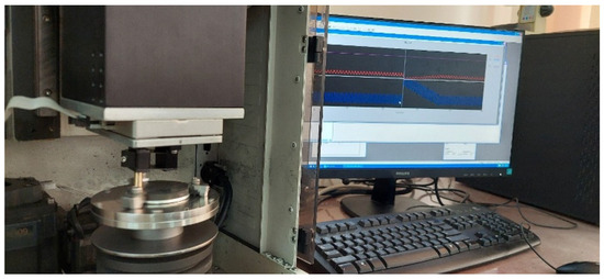
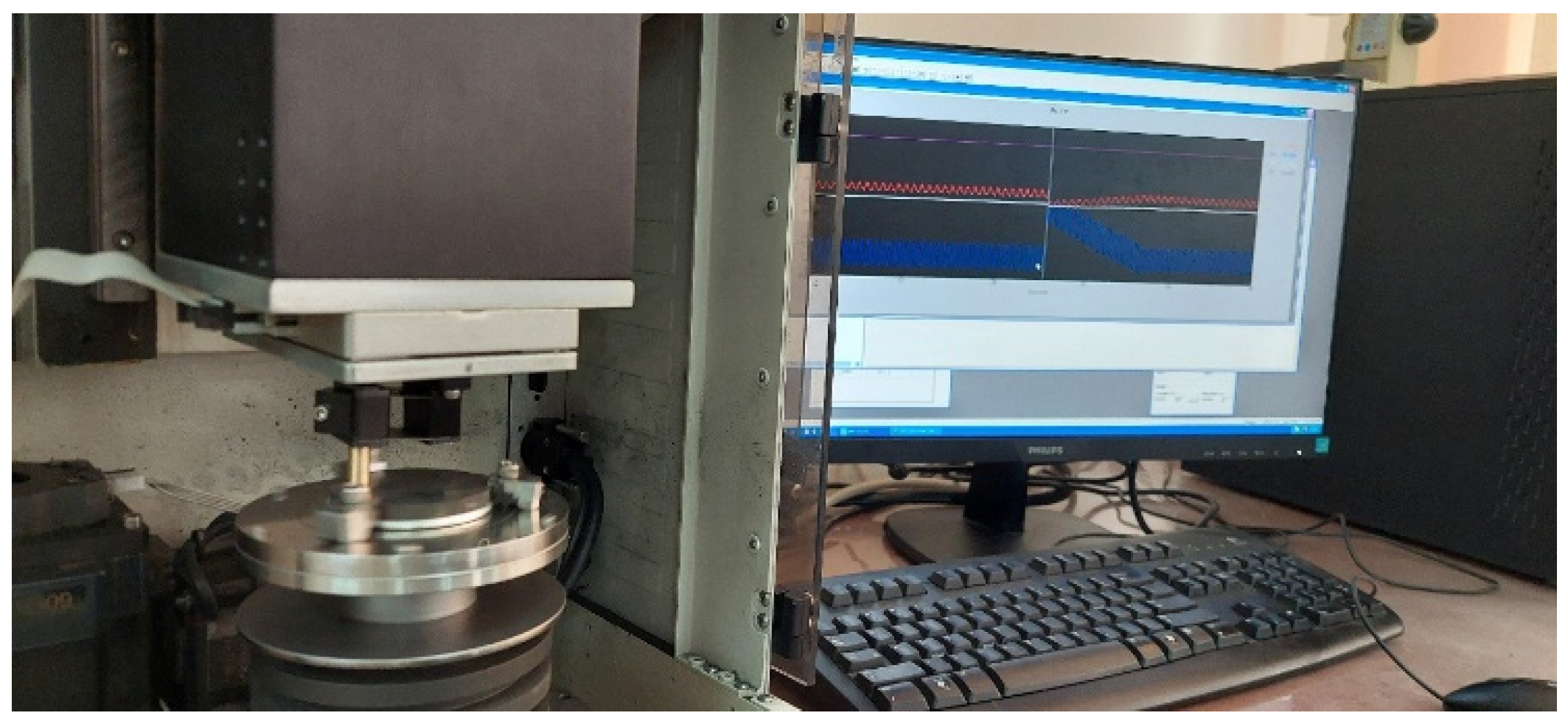
Dry sliding wear tests were performed on the surfaces of five representative samples (S0 from Batch 0, S1 from Batch 1, S2 from Batch 2, S3 from Batch 3 and S4 from Batch 4) using the same CETR UMT-2 tribometer equipped with a pin-on-disc module, according to the ASTM G99-23 standard [32]. The coated specimens served as the rotating discs and were mounted with the coated surface facing upward to ensure direct contact with the counterbody, as illustrated in Figure 1. A cylindrical pin made from commercially available CuSn7Pb7Zn4 bronze (DIN 1705 RG7), with dimensions compliant with the UMT system specifications (Ø 6.5 ± 0.5% mm; h = 20 ÷ 30 mm), was used as the counter-body for each type of coating. The tests were conducted under a constant normal load of 15 N and a rotational speed of 1 revolution per second for a total test duration of 1 h, while the wear track radius was kept constant for all samples. All experiments were carried out under ambient laboratory conditions.
Figure 1.
Aspects during one of the pin-on-disc tests (left side presents the testing system and the right side presents the data acquisition system).
Wear behavior was evaluated using the gravimetric method by measuring the mass loss of the samples before and after testing. All measurements were conducted using a Nimbus electronic balance with high precision.
3. Results
The samples were systematically evaluated at each stage of the experimental workflow to ensure the acquisition of a robust and consistent dataset. This approach enabled detailed comparative analyses between successive processing and testing stages, thereby supporting a comprehensive and reliable final interpretation of the experimental results.
3.1. Characterization of the Coatings
3.1.1. The Morphology of the As-Coated Layers
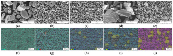
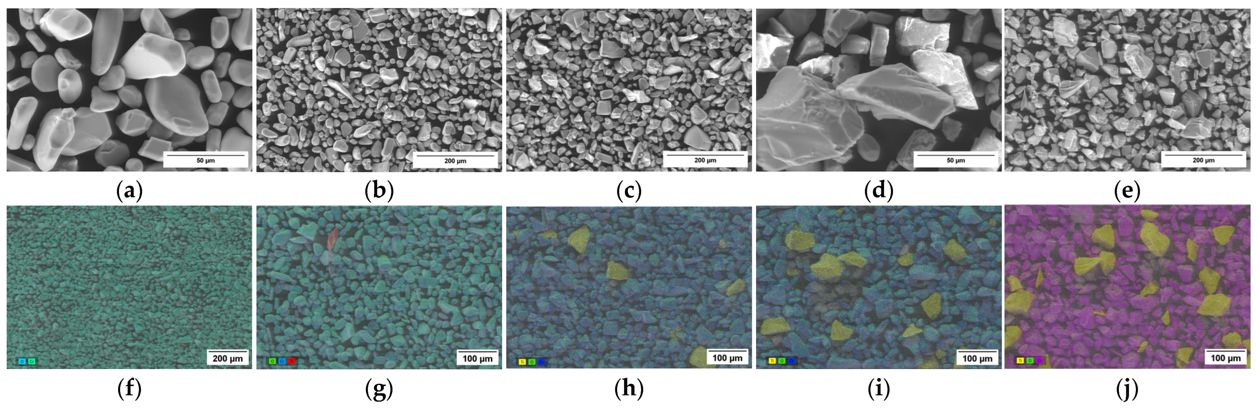
SEM observations of the feedstock powders (P0 from Batch 0, P1 from Batch 1, P2 from Batch 2, P3 from Batch 3, P4 from Batch 4) reveal morphologies typical of ceramic powders obtained by mechanical processing. As presented in Figure 2a–e, two distinct particle morphologies can be clearly identified. The chromium oxide (Cr2O3) particles exhibit predominantly angular shapes with relatively well-defined facets and fractured surfaces characteristic of crushed ceramic oxides, as presented in Figure 2a, which is a detailed view marked with white square in Figure 2f. In contrast, the titanium oxide (TiO2) particles display a more irregular and cornered morphology, with sharper edges and more pronounced surface roughness, as emphasized in Figure 2d (detailed view of the marked area from Figure 2i). A relatively broad particle size distribution is observed for all powder compositions, with coarser particles coexisting with finer fragments, which is generally favorable for atmospheric plasma spraying.
Figure 2.
SEI images and EDS maps of the powders used for: Batch 0 (a,f); Batch 1 (b,g); Batch 2 (c,h); Batch 3 (d,i); Batch 4 (e,j).
EDS distribution maps confirm the compositional characteristics of the powders (Figure 2f–j. Powder P0 (Cr2O3) shows a uniform distribution of chromium and oxygen, indicating a chemically homogeneous feedstock (Figure 2f). In contrast, powders P1–P4 exhibit distinct Cr-rich and Ti-rich regions, consistent with mechanically mixed Cr2O3–nTiO2 powders. The extent and frequency of Ti-rich domains increase with increasing TiO2 content (Figure 2g–j), confirming that no chemical homogenization or solid-solution formation occurs prior to spraying, in agreement with the XRD results.
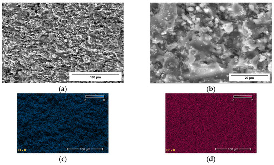
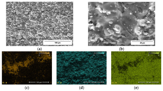
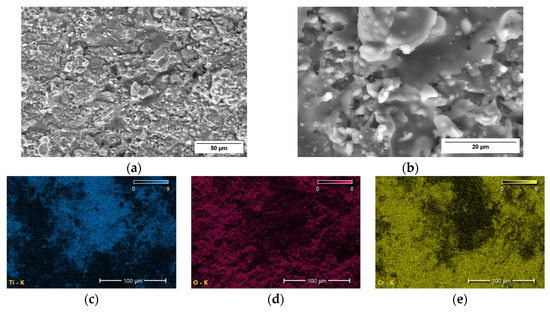
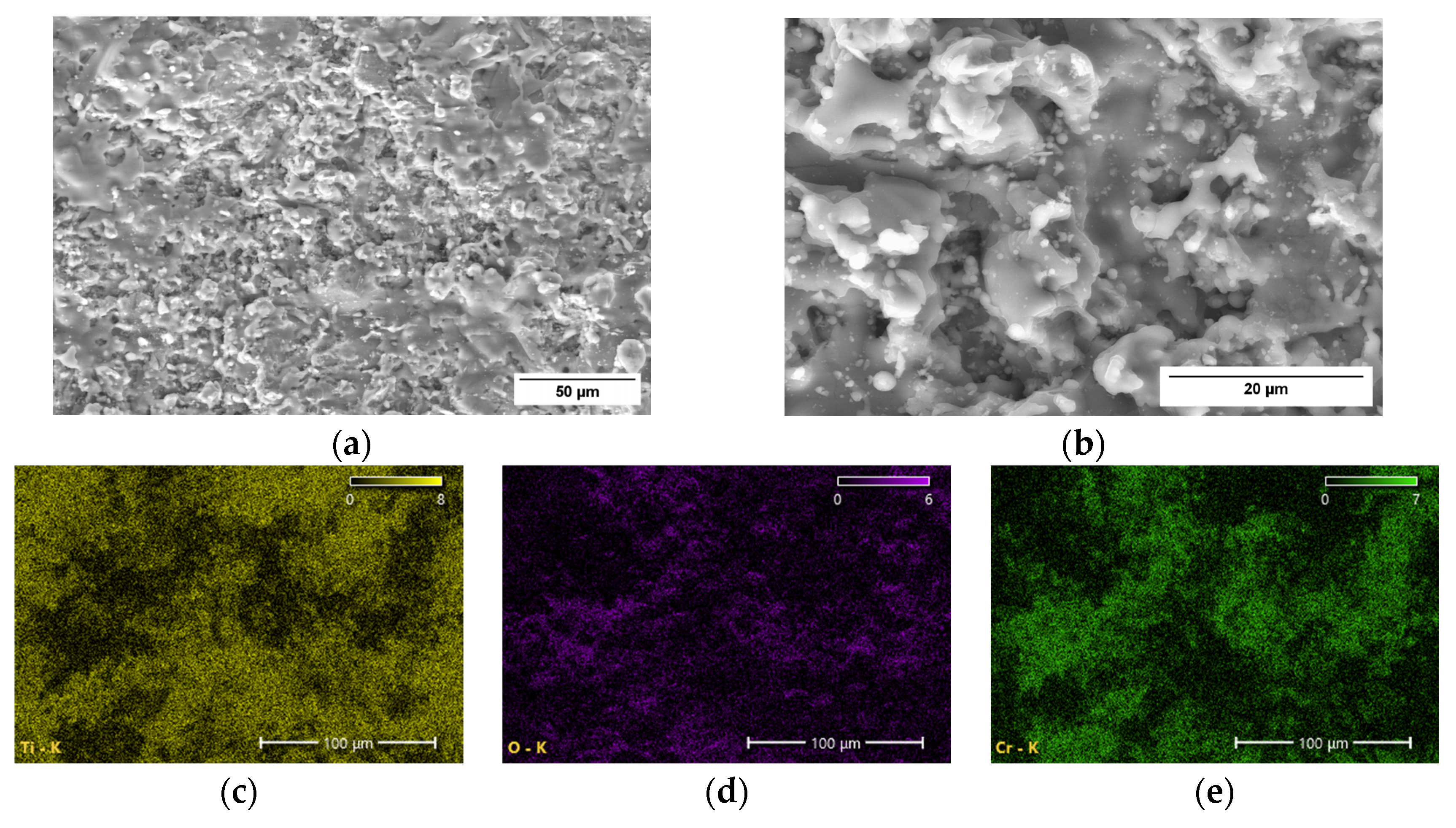
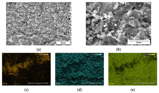
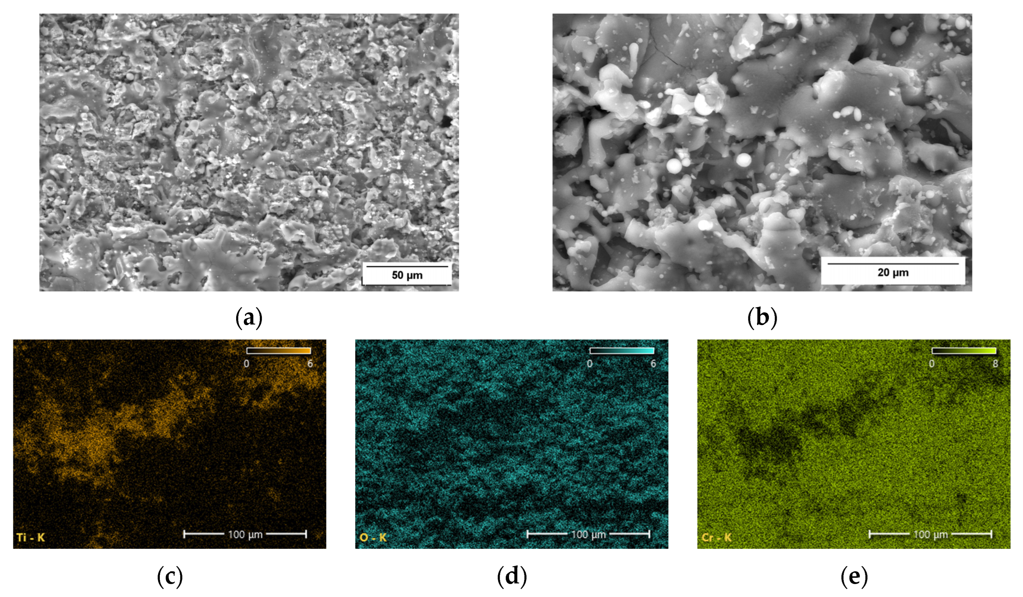
SEM observations of the as-sprayed coatings (S0–S4) reveal surface morphologies characteristic for APS ceramic coatings. All coatings display a rough topography composed of flattened splats, partially melted particles and intersplat boundaries. A fine and uniformly distributed surface porosity is observed, together with occasional semi-molten features, reflecting the rapid quenching and layer-by-layer build-up inherent to the plasma spraying process.
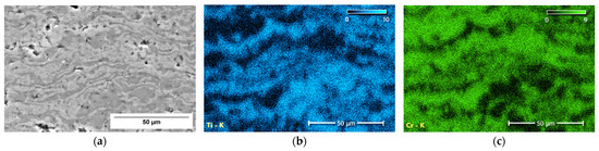
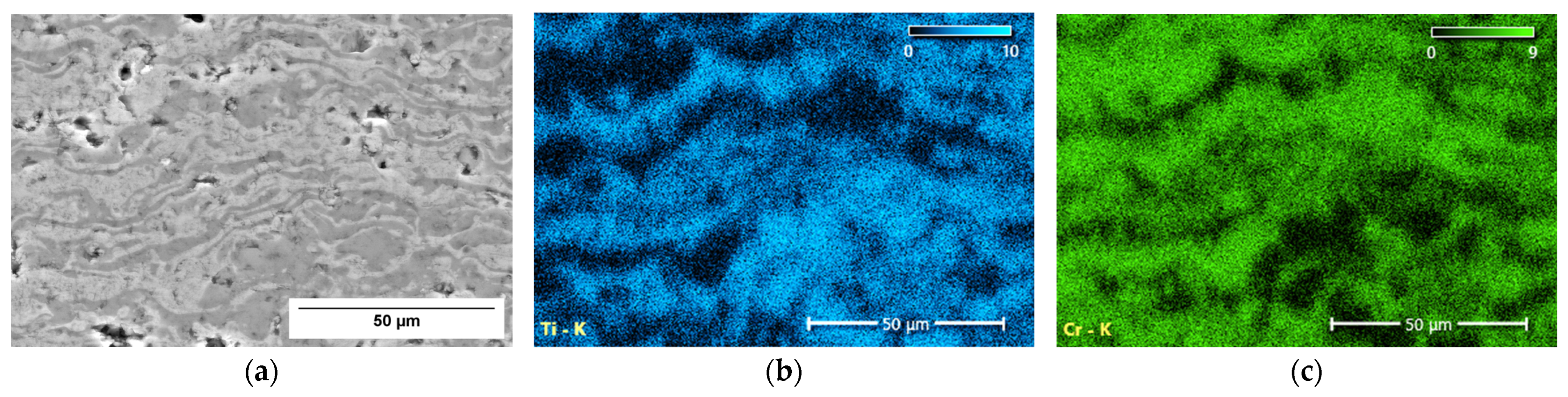
Coating S0 (Figure 3a), deposited from pure Cr2O3 powder, exhibits a relatively uniform lamellar morphology with well-flattened splats and fine intersplat porosity emphasized in Figure 3b. The other coatings S1–S4 (Figure 4, Figure 5, Figure 6 and Figure 7), obtained from Cr2O3–nTiO2 feedstocks, show increased microstructural heterogeneity, including regions with different splat morphologies and contrast variations. EDS mappings reveal a non-uniform distribution of Ti within the coatings, indicating that the composite character of the feedstock powders is largely retained after deposition.
Figure 3.
SEI images (a,b) and EDS maps (c,d) of the S0 as-coated surface.
Figure 4.
SEI images (a,b) and EDS maps (c–e) of the S1 as-coated surface.
Figure 5.
SEI images (a,b) and EDS maps (c–e) of the S2 as-coated surface.
Figure 6.
SEI images (a,b) and EDS maps (c–e) of the S3 as-coated surface.
Figure 7.
SEI images (a,b) and EDS maps (c–e) of the S4 as-coated surface.
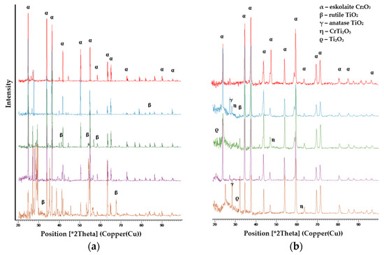
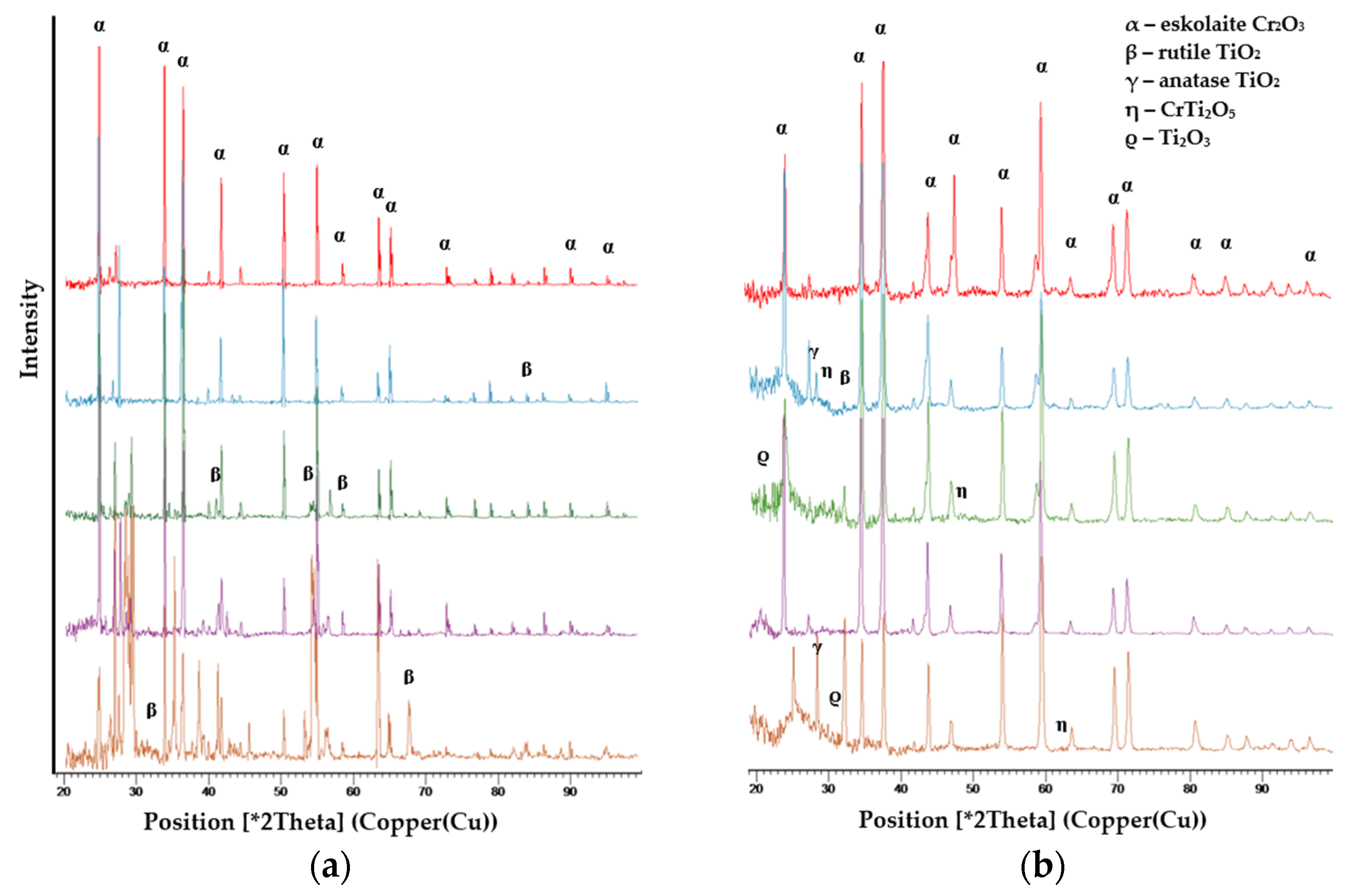
X-ray diffraction (XRD) was used to investigate the phase composition of the feedstock powders (P0–P4) and the corresponding plasma-sprayed coatings (S0–S4) and presented comparatively in Figure 8a,b. Diffraction peaks not attributable to chromium- or titanium-based oxides were assigned to the aluminum holder or substrate and excluded from the analysis.
Figure 8.
Comparative XRD analysis of the powders (a) and coatings (b) for all batches: red—Batch 0, blue—Batch 1, green—Batch 2, magenta—Batch 3, orange—Batch 4.
The diffraction pattern of powder P0 confirms the presence of eskolaite-type Cr2O3 as a single crystalline phase. For powders P1–P4, containing increasing amounts of TiO2 (10–40 wt%), the XRD patterns show the coexistence of Cr2O3 and TiO2, with rutile TiO2 reflections becoming progressively more intense as the TiO2 content increases. No mixed chromium–titanium oxide phases are detected in the feedstock powders, indicating that they consist of physical mixtures of the two oxides.
In contrast, the XRD patterns of the plasma-sprayed coatings exhibit a more complex phase composition. While Cr2O3 and TiO2 are still identified in all coatings, additional diffraction peaks are observed in coatings deposited from TiO2-containing powders. These peaks cannot be fully explained by a simple superposition of the initial oxides and are consistent with the possible formation of chromium–titanium oxide phases, such as CrTi2O5-type compounds, during plasma spraying. In some coatings, reflections compatible with reduced titanium oxide phases (e.g., Ti2O3) are also observed, suggesting a partial reduction in TiO2 under the high-temperature plasma conditions.
Compared to the powders, the diffraction peaks of the coatings are broader, which is attributed to rapid solidification, residual stresses, and microstructural refinement induced by the plasma spraying process.
3.1.2. The Morphology of the Finished Layers
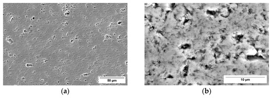
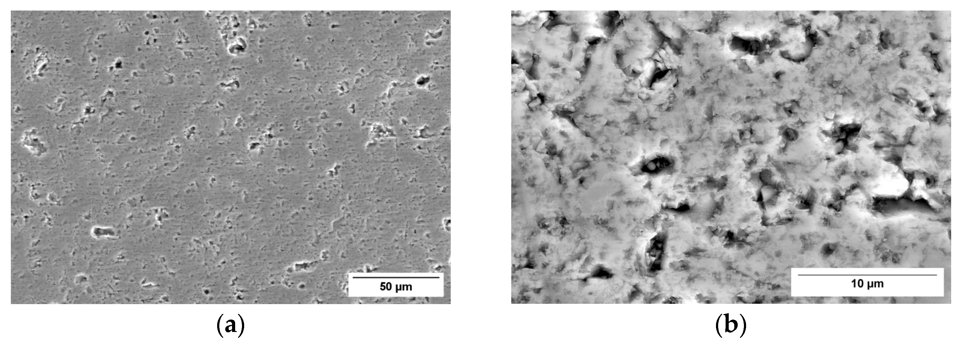
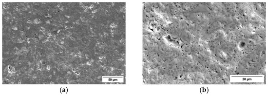
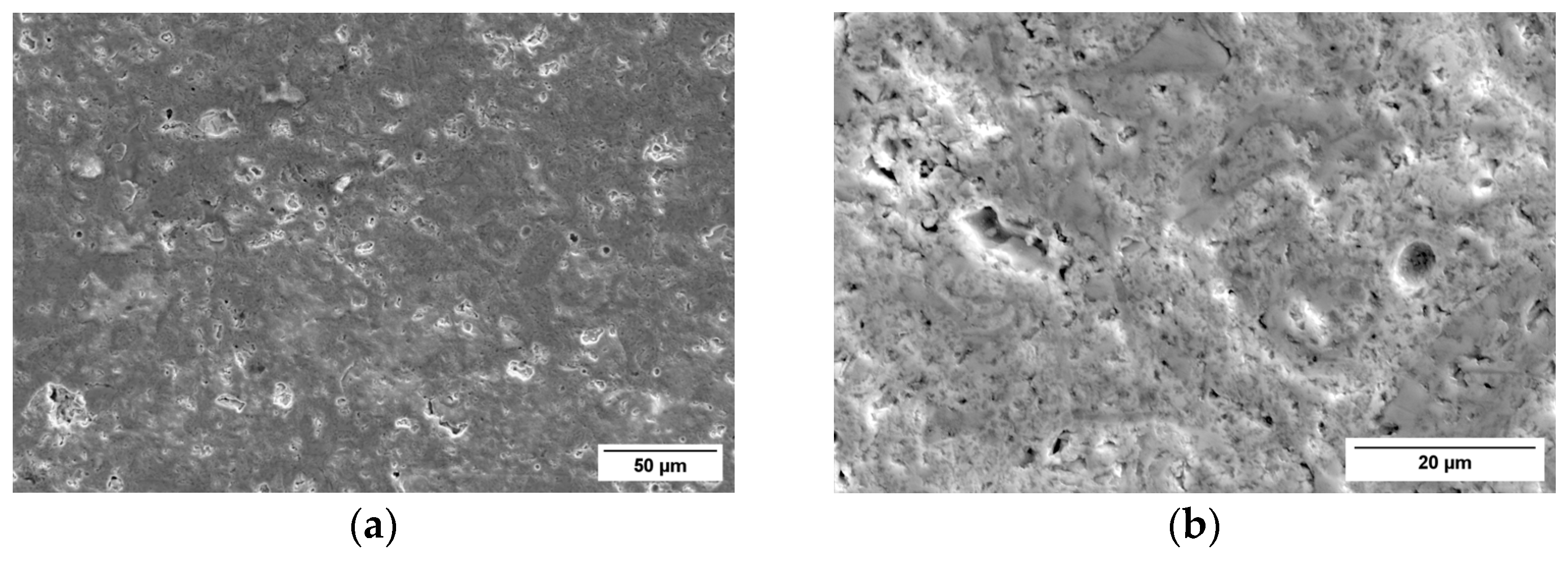
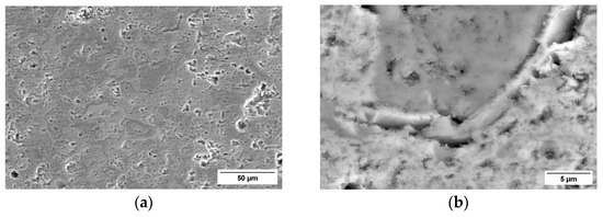
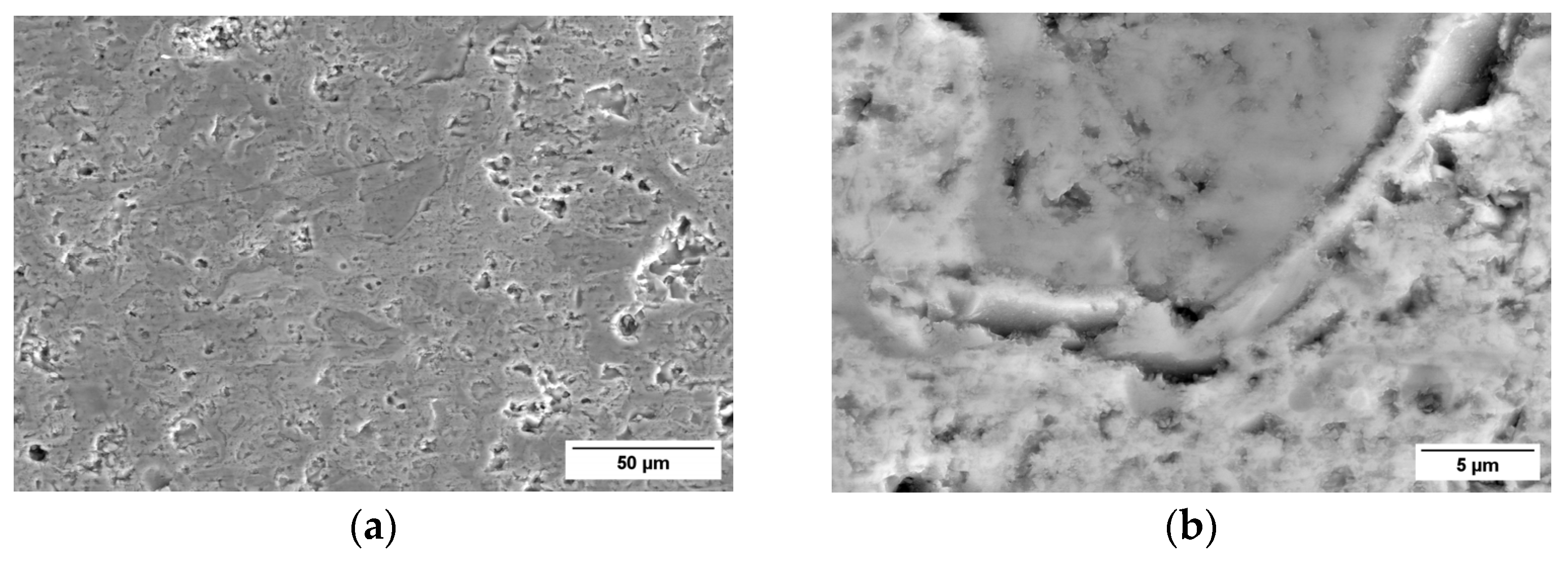
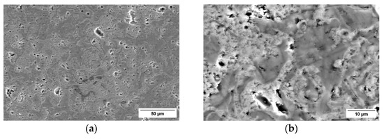
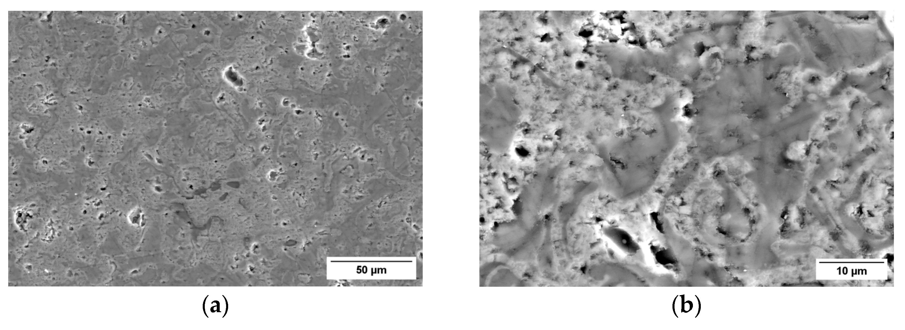
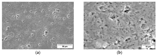
The surface morphology of the plasma-sprayed coatings after mechanical grinding and polishing was investigated by SEM at low (500×) and high magnifications (1600× and 4000×). Representative SEM images of the finished surfaces are shown in Figure 9, Figure 10, Figure 11, Figure 12 and Figure 13a,b. In addition, surface roughness measurements were performed in order to quantitatively assess the effect of mechanical finishing.
Figure 9.
SEI of the S0 finished surface at different magnification: (a) 500×; (b) 4000×.
Figure 10.
SEI of the S1 finished surface at different magnification: (a) 500×; (b) 1600×.
Figure 11.
SEI of the S2 finished surface at different magnification: (a) 500×; (b) 4000×.
Figure 12.
SEI of the S3 finished surface at different magnification: (a) 500×; (b) 2000×.
Figure 13.
SEI of the S4 finished surface at different magnification: (a) 500×; (b) 2000×.
At 500× magnification (Figure 9, Figure 10, Figure 11, Figure 12 and Figure 13a), all coatings exhibit a uniform and continuous surface morphology, without visible macroscopic damage induced by the finishing process. No surface cracks, delamination, exfoliation, or material pull-outs are observed, indicating that grinding and polishing did not compromise the coating integrity. At higher magnifications (Figure 9, Figure 10, Figure 11, Figure 12 and Figure 13b), it is obvious that the microstructure remains relatively compact, with flattened splats and interlamellar regions still clearly identifiable. A fine and uniformly distributed porosity is observed, which is characteristic of plasma-sprayed ceramic coatings and does not show signs of enlargement or preferential opening due to mechanical processing.
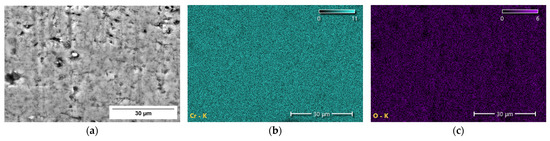
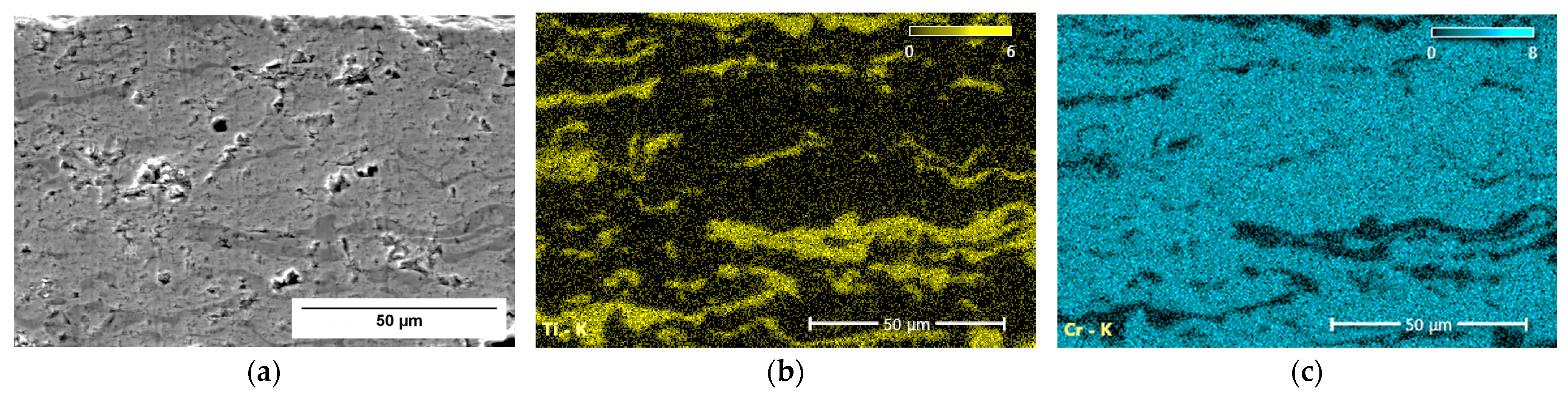
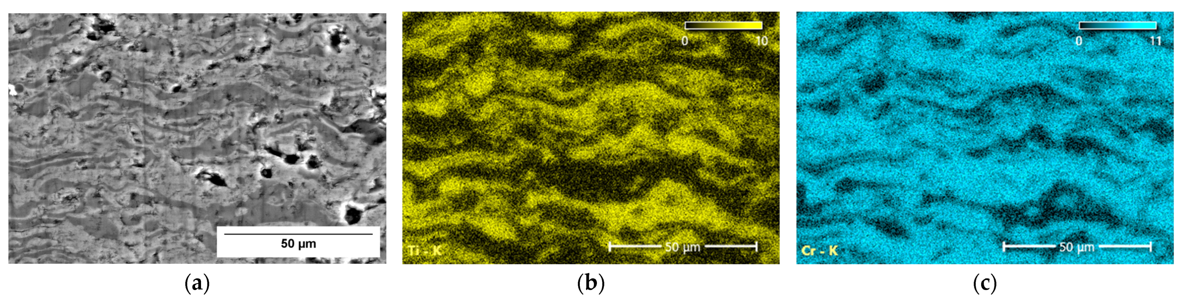
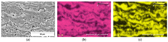
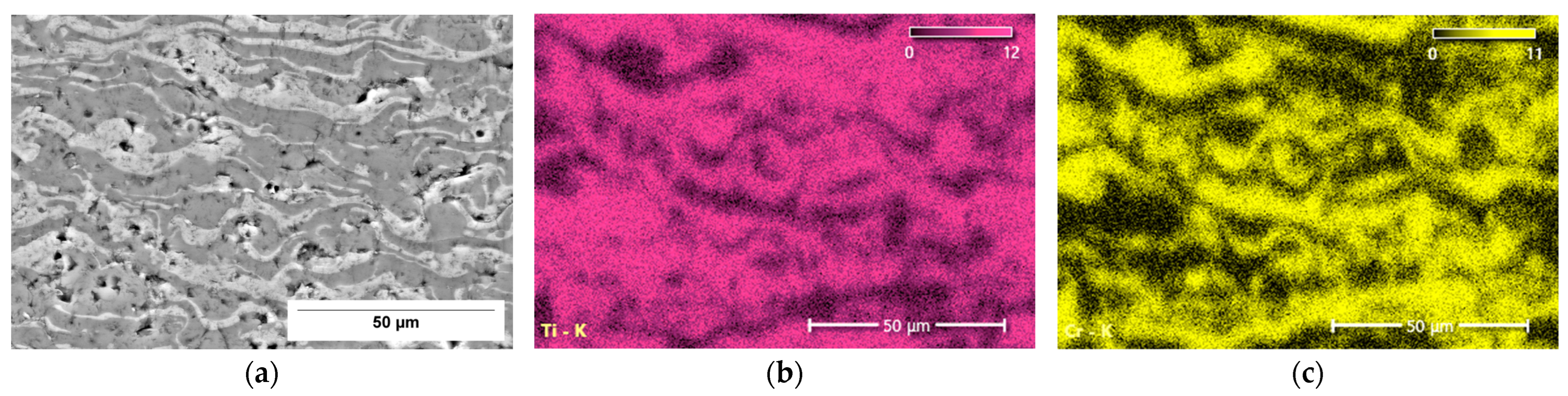
The cross-sectional SEM images presented in Figure 14, Figure 15, Figure 16, Figure 17 and Figure 18, reveal the typical lamellar microstructure characteristic of coatings produced by atmospheric plasma spraying. As previously discussed, this structure is formed by successive deposition and rapid solidification of molten particles, resulting in flattened splats (lamellae) stacked across the coating thickness. As commonly observed in plasma-sprayed ceramic coatings, the microstructure also contains inclusions and interlamellar voids that generate a certain level of porosity. In this case, such porosity is not necessarily detrimental, as it can contribute to stress accommodation within the coating and may influence tribological behavior under dry friction conditions.
Figure 14.
(a) SEI images (1500× magnification) and EDS distribution map of Cr (b) and O (c) of the S0 cross-section surface.
Figure 15.
(a) SEI images (1000× magnification) and EDS distribution map of Ti (b) and Cr (c) of the S1 cross-section surface.
Figure 16.
(a) SEI images (1000× magnification) and EDS distribution map of Ti (b) and Cr (c) of the S2 cross-section surface.
Figure 17.
(a) SEI images (1000× magnification) and EDS distribution map of Ti (b) and Cr (c) of the S3 cross-section surface.
Figure 18.
(a) SEI images (1000× magnification) and EDS distribution map of Ti (b) and Cr (c) of the S4 cross-section surface.
The cross-sectional observations also allowed the measurement of the average coating thickness for each sample. The mean thickness was approximately 98 µm for S0, 125 µm for S1, 134 µm for S2, 158 µm for S3, and 179 µm for S4, indicating a gradual increase in coating thickness across the sample series. In addition, the elemental distribution maps presented in Figure 14, Figure 15, Figure 16, Figure 17 and Figure 18b,c highlight the progressive increase in titanium content across the sample series. Starting from sample S0, which does not contain titanium oxide, the titanium signal becomes increasingly pronounced in samples S1 (10% TiO2), S2 (20% TiO2), S3 (30% TiO2), and S4 (40% TiO2), confirming the intended compositional variation in the coatings.
The roughness measurements summarized in Table 1 show low average roughness values for all finished coatings, with Raavg ranging between approximately 0.122 and 0.162 µm. These low values confirm the effectiveness of the grinding and polishing procedures in reducing surface asperities. Minor variations in Ra between individual measurements reflect the intrinsic microstructural heterogeneity of thermally sprayed coatings, associated with splat boundaries and fine pores. No systematic increase in roughness with coating composition is observed, indicating that the TiO2 content does not adversely affect the surface finishability.
Table 1.
Roughness values determined on the finished surfaces of the studied samples.
Overall, the combined SEM observations and roughness data demonstrate that mechanical finishing produces smooth, defect-free surfaces while preserving the characteristic lamellar and porous microstructure of the plasma-sprayed coatings.
3.1.3. Mechanical Properties of the Finished Layers
The mechanical properties of the plasma-sprayed coatings were evaluated by scratch testing under constant and progressive loading conditions up to 15 N, complemented by instrumented indentation and Vickers microhardness measurements. These techniques provide a comprehensive assessment of the coatings’ resistance to contact loading, deformation and damage initiation.
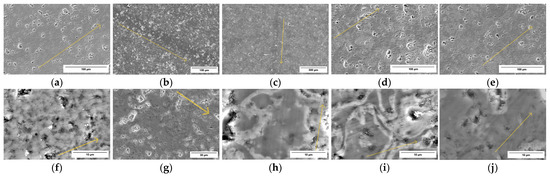
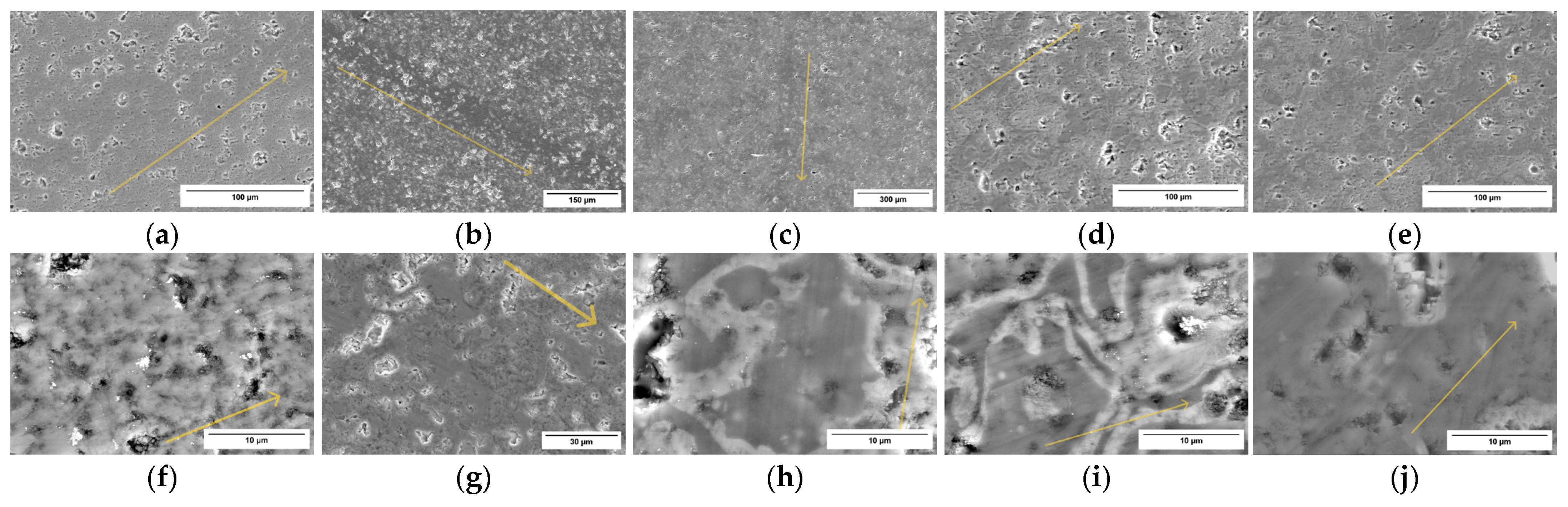
SEM analysis of the scratch marks (Figure 19a–j) obtained under constant load reveals continuous and well-defined grooves for all investigated coatings, without evidence of catastrophic failure such as large-scale delamination, spallation, or coating detachment. The dominant damage mechanisms consist of local plastic deformation, limited microfracturing and minor material removal along the scratch edges.
Figure 19.
SEI images of the scratch marks obtained at the constant—load test, representative for each batch, at different magnification: S0 ((a)—500×; (f)—4000×); S1 ((b)—200×; (g)—1000×); S2 ((c)—100×; (h)—4000×); S3 ((d)—500×; (i)—4000×); S4 ((e)—500×; (j)—4000×). The yellow marks represent the scratch direction.
Coatings deposited from P0 (pure Cr2O3, Figure 19a,f) and P1 (Cr2O3 + 10 wt% TiO2, Figure 19b,g) exhibit the narrowest and most regular scratch marks, indicating a higher resistance to scratch-induced deformation. In contrast, the coating produced from P2 (20 wt% TiO2, Figure 19c,h) shows wider grooves and more pronounced material displacement, suggesting a reduced resistance to contact loading. Coatings from P3 (Figure 19d,i) and P4 (Figure 19e,j) display intermediate behavior, characterized by localized microcracks and limited debris formation, without signs of interlamellar delamination.
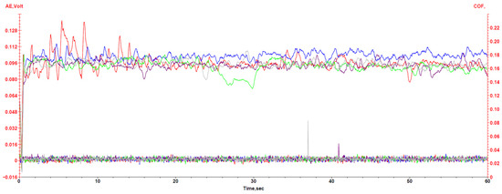
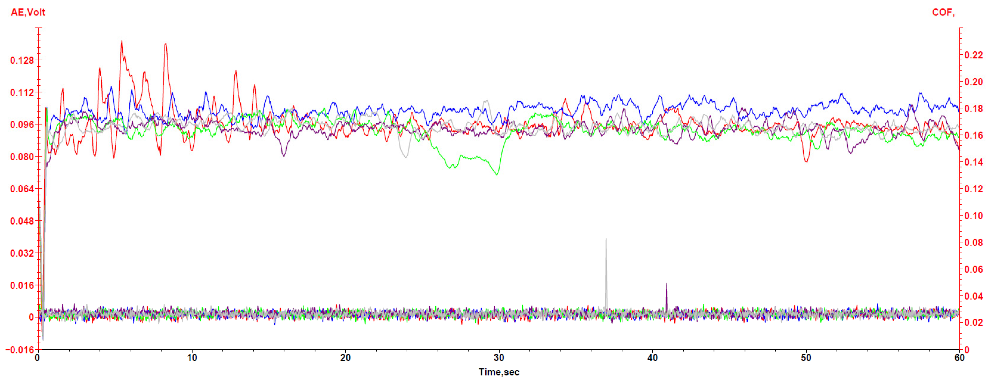
The coefficient of friction (COF—upper part of the graph) curves recorded during constant-load scratch test, presented comparatively in Figure 20, are relatively stable for all coatings, with no abrupt changes or pronounced acoustic emission (AE—lower part of the graph) events. This indicates that no sudden failure mechanisms are activated under the sustained load of 15 N.
Figure 20.
Comparative COF (upper) and AE (lower) resulted at the scratch test with constant load, for each representative sample: red—S0, blue—S1, green—S2, magenta—S3, gray—S4.
During progressive-load scratching, all coatings exhibit a gradual increase in COF with increasing applied load, as presented comparatively in Figure 21. No critical load associated with coating failure is identified within the investigated load range. Coatings with lower TiO2 content (S0 and S1) show smoother COF evolution and lower absolute COF values, whereas coatings with higher TiO2 content (S2–S4) display increased COF levels and greater variability, reflecting enhanced microfracture activity and local compliance differences.
Figure 21.
Comparative COF resulted at the scratch test with progressive load, for each representative sample: red—S0, blue—S1, green—S2, magenta—S3, gray—S4.
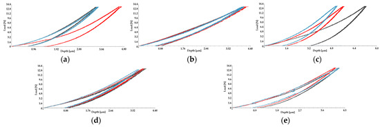
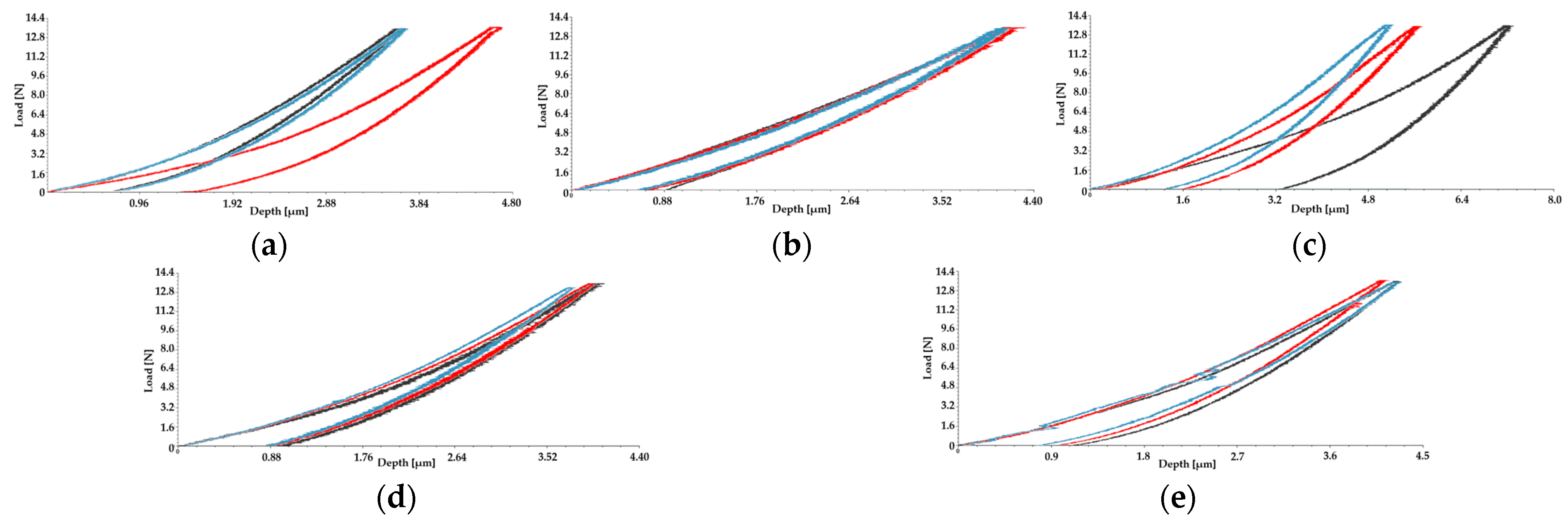
The instrumented indentation load–displacement (P–h) curves presented in Figure 22 with different color for each different indentation on the same sample, acquired at a maximum load of 15 N, reveal distinct mechanical responses among the five APS ceramic coatings (S0–S4). All tests were conducted under identical loading conditions, enabling the direct comparison of penetration behavior and elastic recovery.
Figure 22.
Typical load–displacement curves obtained by indentation onto the representative samples: S0 (a); S1 (b); S2 (c); S3 (d); S4 (e).
S0 (Figure 22a) and S1 (Figure 22b) exhibited the lowest maximum penetration depths, consistent with their relatively high resistance to plastic deformation. The loading segments for these coatings were smooth and nearly overlapping across repeated measurements, indicating homogeneous mechanical behavior at the indentation scale. The unloading slopes for S1, in particular, were relatively steep, suggesting higher effective stiffness and elastic recovery compared to the other samples.
In contrast, S2 (Figure 22c) demonstrated significantly greater penetration depths under the same load, indicative of reduced resistance to deformation. The corresponding P–h curves for S2 also displayed increased scatter among repeats, which suggests a more heterogeneous microstructure with variations in local compliance. S3 (Figure 22d) showed intermediate penetration depths between S1 and S0 on one hand and S2 on the other, with relatively consistent curves, pointing to moderate hardness and a uniform response. S4 (Figure 22e) exhibited penetration depths similar to S1 and S3, but notable discontinuities were observed on the loading segments for one of the repeats, indicating localized instabilities such as microcracking or inter-lamellar decohesion under contact loading.
To contextualize these observations and the values extracted from indentation tests (EIT—elastic indentation modulus of the material/Young’s module; HIT—indentation hardness) with conventional hardness metrics, Vickers microhardness (HV2) measurements were performed on a Shimadzu HMV-2E Microhardness tester [33,34].
Although the trends obtained from instrumented indentation and Vickers microhardness are generally comparable, some differences between the measured values can be observed. These variations are mainly related to the lamellar microstructure characteristic of APS coatings. During instrumented indentation, the indenter interacts with a very small material volume, which may locally include dense splats, interlamellar boundaries or pores. As a result, the measured elastic modulus (EIT) and indentation hardness (HIT) can vary depending on the local microstructural configuration.
In contrast, Vickers microhardness measurements involve a larger indentation footprint and therefore average the response of a greater material volume. Consequently, the HV2 values reported in Table 2 show smaller variations but do not perfectly follow the same trend as the indentation-derived parameters. This difference reflects the microstructural heterogeneity of plasma-sprayed coatings and the higher sensitivity of instrumented indentation to local variations in splat cohesion, interlamellar bonding and porosity.
Table 2.
Characteristic material values resulted during tests.
3.2. Dry Sliding Wear Behavior
The dry sliding wear behavior of the five investigated coatings was evaluated by combining surface morphology observations, frictional response analysis and gravimetric measurements following the pin-on-disc tests.
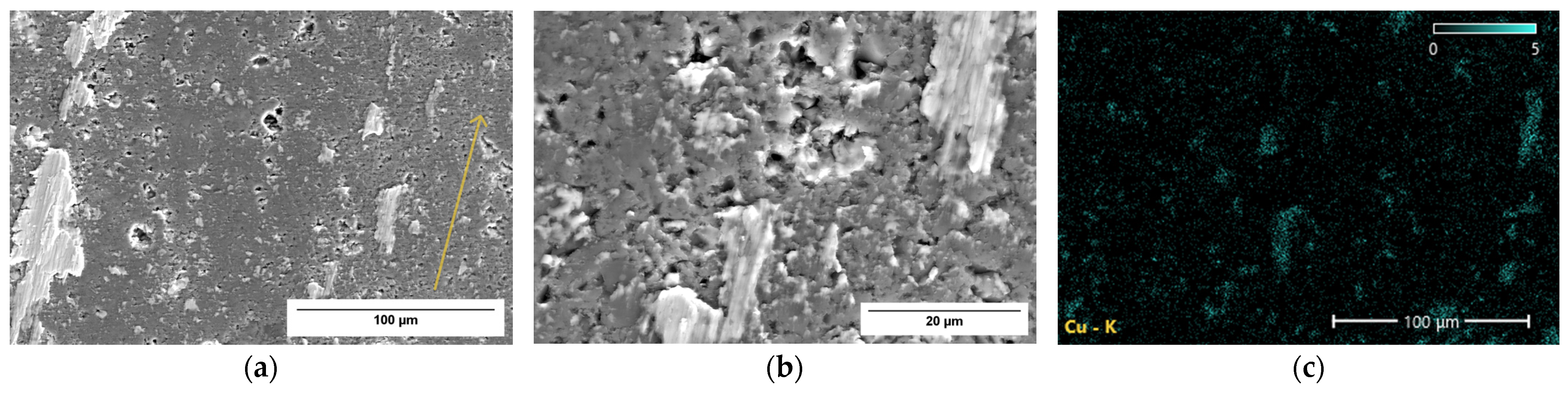
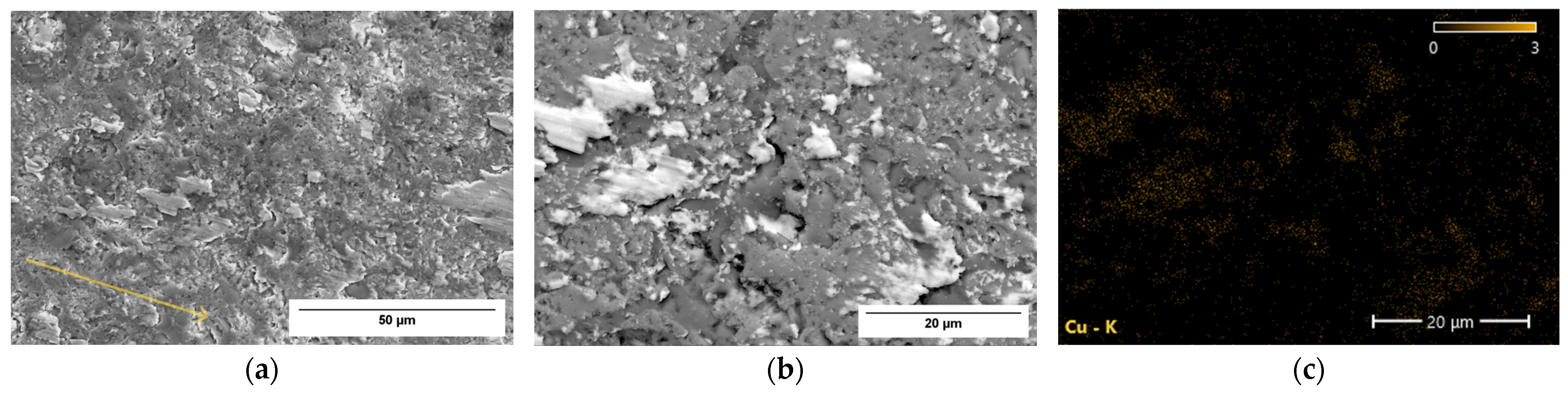
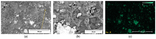
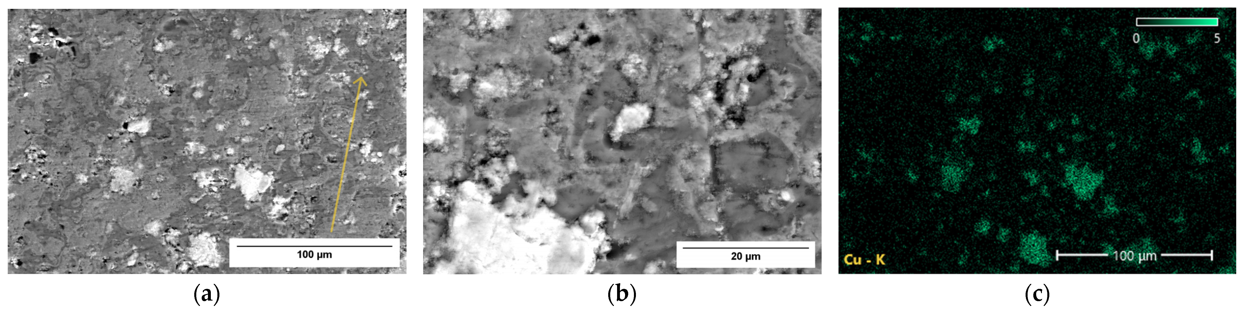
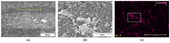
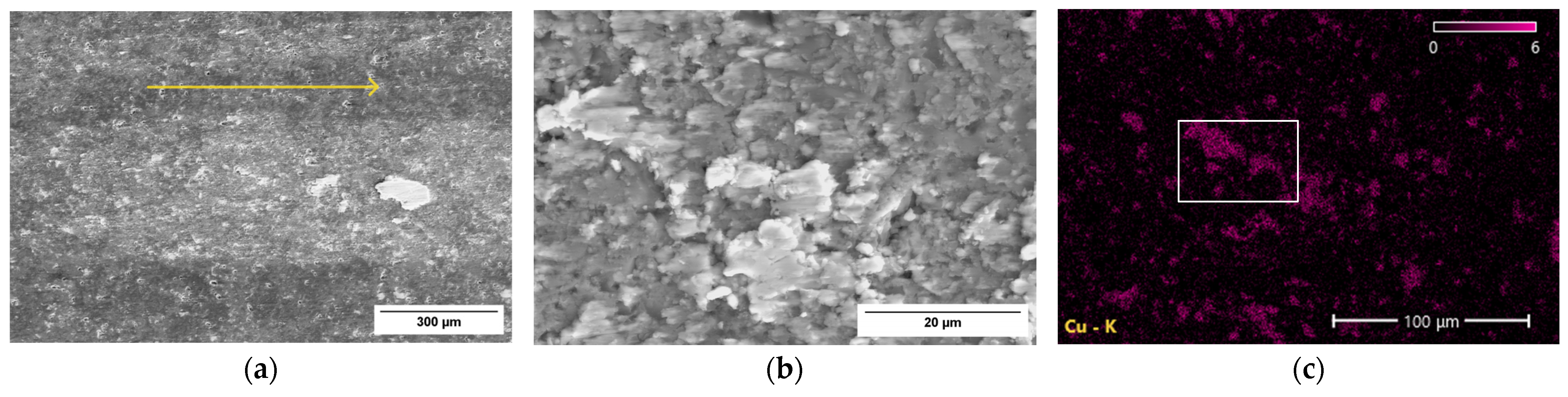
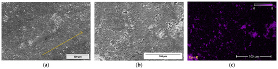
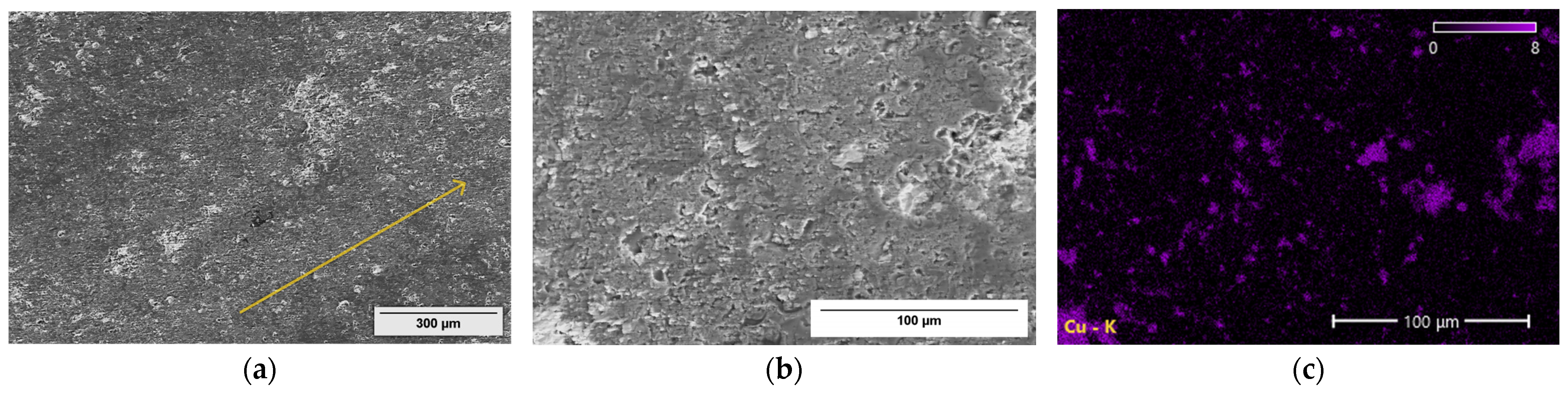
Representative SE images of the wear tracks for S0–S4 are presented in Figure 23, Figure 24, Figure 25, Figure 26 and Figure 27a,b. For all samples, the wear tracks are clearly defined and oriented along the sliding direction (marked with yellow arrows). No evidence of coating exfoliation or delamination was observed for any of the investigated batches. The surface features observed within the wear tracks are characterized by grooves, smeared regions and compacted debris, whose appearance varies between samples.
Figure 23.
SEI images ((a)—500×, (b)—2000×), EDS Cu—distribution map (c) of the S0 wear-track surface.
Figure 24.
SEI images ((a)—1000×, (b)—2000×), EDS Cu—distribution map (c) of the S1 wear-track surface.
Figure 25.
SEI images ((a)—500×, (b)—200×), EDS Cu—distribution map (c) of the S2 wear-track surface.
Figure 26.
SEI images ((a)—100×, (b)—2000×), EDS Cu—distribution map (c) of the S3 wear-track surface.
Figure 27.
SEI images ((a)—100×, (b)—500×), EDS Cu—distribution map (c) of the S4 wear-track surface.
EDS elemental mapping focused on copper distribution (Figure 23, Figure 24, Figure 25, Figure 26 and Figure 27c) reveals the presence of material transferred from the bronze counter-body onto the coating surfaces. In S0 case, copper-rich regions are discontinuously distributed along the wear track, indicating limited material transfer.
S1 exhibits a more uniform copper distribution, suggesting the formation of a relatively continuous transfer layer during sliding. On the S2 surface, the copper signal appears locally intensified and non-uniform, reflecting intermittent material transfer and spatial variations along the wear track. S3 shows an increased extent of copper coverage compared to S0–S2, while S4 presents the most extensive copper-rich areas, with large portions of the wear track covered by transferred bronze material. In all cases, the observed surface contrast variations are associated with the presence and redistribution of transferred bronze rather than the damage or removal of the ceramic coating.
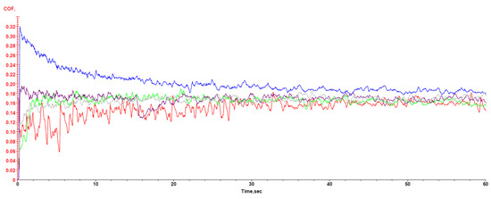
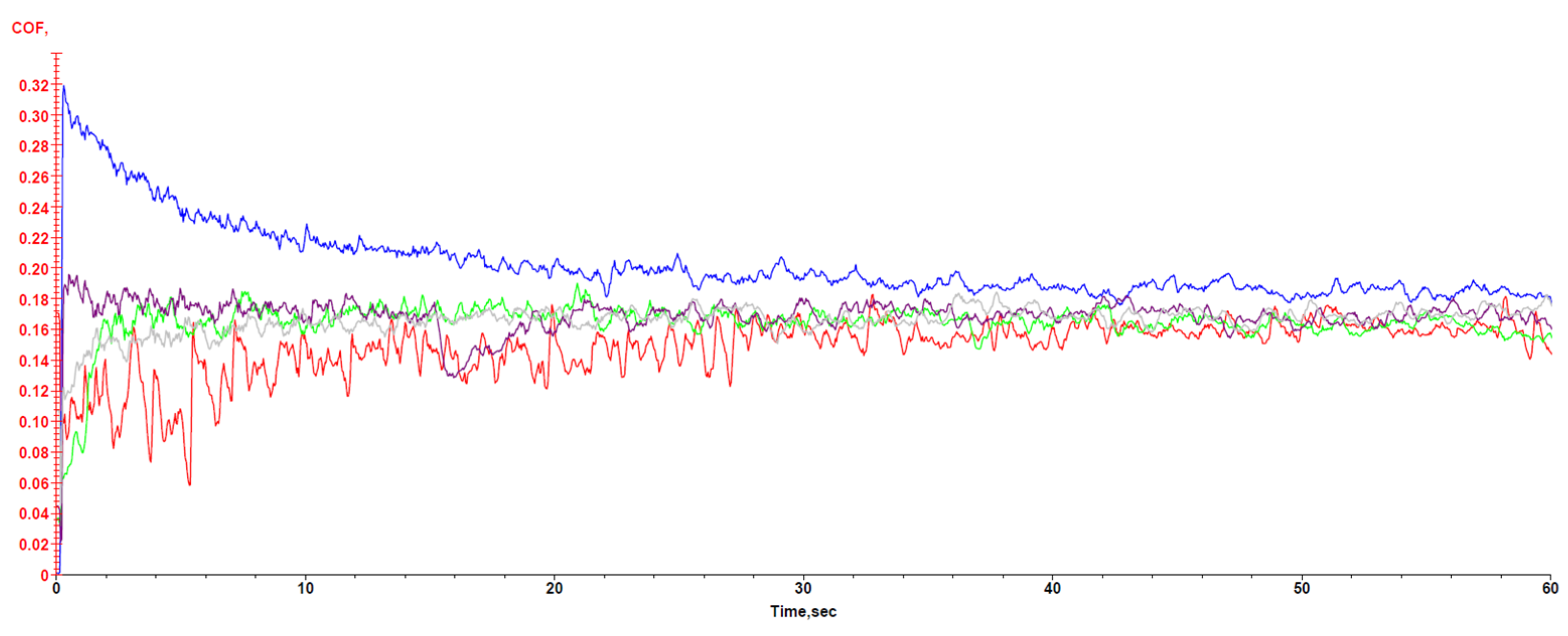
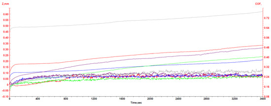
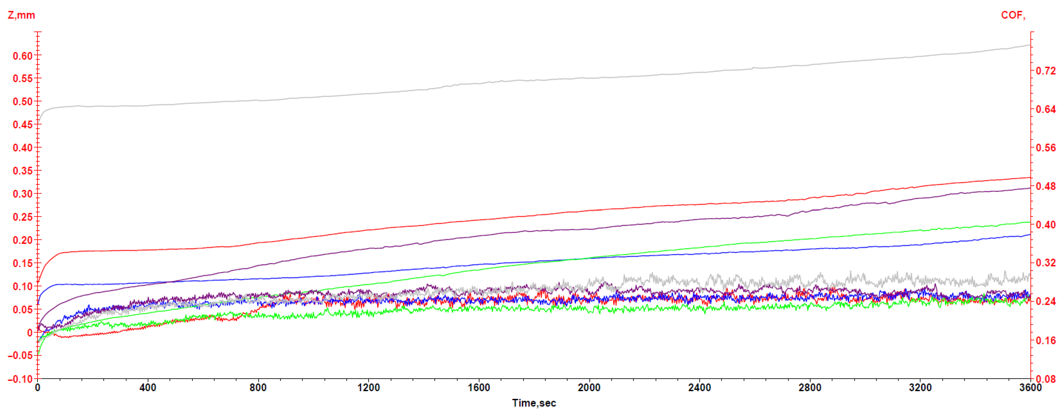
The evolution of the coefficient of friction (COF) and the Z parameter, corresponding to the carriage position used to estimate wear depth, is shown in Figure 28 for all batches. Distinct frictional responses were recorded. S0 and S1 exhibit relatively stable COF values throughout the test duration, with limited fluctuations. S2 displays increased COF variability, while S3 and S4 show more pronounced fluctuations. The Z parameter follows similar trends, with a more gradual evolution for S0 and S1 and a steeper progression for S3 and S4, indicating differences in wear development during sliding.
Figure 28.
Comparative Z variation (upper) and COF variation (lower) resulted at pin-on-disc tests, for each representative sample: red—S0, blue—S1, green—S2, magenta—S3, gray—S4.
Gravimetric measurements of the bronze pins before and after testing are summarized in Table 3. The recorded mass losses increase progressively from S0 to S4. The lowest mass variations were measured for S0 and S1, while intermediate values were obtained for S2. Higher mass losses were recorded for S3 and S4, indicating increased material removal from the counter-body during sliding. These gravimetric results are consistent with the observed extent of copper transfer identified by EDS analysis.
Table 3.
Gravimetric measurements of the bronze pins before and after testing.
Overall, the combined SEM, EDS, frictional, and gravimetric results demonstrate clear differences in the sliding wear response among the investigated batches. The wear tracks are primarily characterized by groove formation and bronze material transfer, with no evidence of coating exfoliation for any of the samples. Differences between batches are reflected in the extent and uniformity of the transferred material, the stability of the frictional response and the magnitude of counter-body mass loss.
4. Discussion
The experimental results reveal a clear interdependence between composition, phase constitution, microstructural architecture, and the mechanical response of the plasma-sprayed Cr2O3–nTiO2 coatings. XRD analysis indicates that, while the feedstock powders consist exclusively of Cr2O3 (eskolaite) and TiO2 (rutile), the plasma spraying process induces phase modifications in the coatings, leading to the formation of additional chromium–titanium oxide phases. This phase evolution reflects local chemical interactions occurring during deposition and contributes to the compositional heterogeneity observed in the as-sprayed state.
SEM observations show that all coatings exhibit a lamellar microstructure with intrinsic porosity, characteristic of plasma-sprayed ceramic systems. The fine and relatively homogeneous pore distribution results from rapid splat solidification and incomplete interlamellar bonding. Importantly, mechanical finishing does not alter this architecture, as no cracking, delamination, or exfoliation is detected. This indicates that the lamellar structure maintains sufficient cohesion and integrity under surface material removal, preserving the essential microstructural features governing mechanical behavior.
The tribological response of the coatings developed in this study can be interpreted by comparison with previously published research on plasma-sprayed Cr2O3–TiO2 systems. In the present investigation, the pin-on-disc experiments were carried out under a constant normal load of 15 N, with a sliding velocity of about 0.1 m/s (corresponding to 1 revolution per second) in laboratory conditions. A bronze counter-body made from a CuSn-based alloy was selected in order to reproduce the material typically used for bushing components. These experimental conditions differ from many studies reported in the literature, where steel pins are usually employed as counter-surfaces and higher sliding speeds are often applied. For instance, Singh et al. examined Cr2O3–3 wt% TiO2 coatings under loads ranging from 10 to 20 N and sliding speeds close to 0.5 m/s, reporting wear reductions of roughly 20–35% compared with pure Cr2O3 layers. Similarly, Bagde et al. studied Cr2O3–TiO2 coatings at loads between 10 and 30 N and observed decreases in the friction coefficient of approximately 10–25%, which were associated with the formation of protective tribofilms. Bastakys et al. also reported friction coefficients typically between 0.5 and 0.7 for APS Cr2O3-based coatings tested under loads from 5 to 15 N against metallic counterfaces.
The coatings produced in this study show microhardness values ranging from about 877 HV2 to 1198 HV2, which is consistent with the hardness interval of roughly 900–1200 HV commonly reported for APS Cr2O3–TiO2 coatings. A notable difference in the current study is the use of a bronze counterbody rather than steel, which better represents the real contact conditions encountered in king pin–bushing assemblies used in heavy-duty vehicle steering systems. Under these testing conditions, gravimetric measurements indicated bronze mass losses between 0.0295 g and 0.0473 g, with the coatings containing higher Cr2O3 fractions showing the lowest levels of material transfer. The difference between the best-performing coating (S0) and the coating with the highest TiO2 content (S4) corresponds to an approximately 38% reduction in counterbody wear. These findings suggest that although the mechanical properties of the coatings are comparable to those reported in earlier studies, the tribological performance is strongly affected by the specific contact configuration and by the nature of the counterbody material. Therefore, the results obtained here provide more relevant insight for practical king pin–bushing applications, where bronze components operate under dry sliding and oscillatory contact conditions, and they underline the potential of Cr2O3-rich APS coatings to enhance wear resistance and friction stability in such systems.
5. Conclusions
Plasma-sprayed Cr2O3–nTiO2 coatings with varying TiO2 content were systematically characterized in terms of phase constitution, microstructure, mechanical response, and dry sliding wear behavior. The results show that plasma spraying induces phase modifications relative to the feedstock powders, leading to the formation of additional chromium–titanium oxide phases and to a lamellar microstructure with intrinsic porosity in all coatings.
SEM analysis confirmed that the lamellar architecture and fine porosity are inherent to the deposition process and remain stable after mechanical finishing, with no evidence of cracking, delamination, or exfoliation. Mechanical testing revealed a strong dependence of deformation behavior on composition, with Cr2O3-rich coatings exhibiting higher microhardness, lower indentation penetration depths and enhanced resistance to scratch-induced damage, while increasing TiO2 content led to greater mechanical heterogeneity.
All coatings withstood scratch loading up to 15 N without catastrophic failure, highlighting the ability of the lamellar and moderately porous structure to accommodate localized stresses. Dry sliding wear results demonstrated that wear resistance is governed not solely by hardness, but by the stability of the elastic–plastic response under repeated contact loading, as reflected by the combined microhardness and instrumented indentation behavior.
Overall, the results underline the importance of composition-controlled microstructural and mechanical stability in determining the performance of plasma-sprayed Cr2O3–nTiO2 coatings. Future work will focus on optimizing deposition parameters and compositional gradients to further enhance deformation stability and wear resistance under complex contact conditions.
Author Contributions
Conceptualization, D.C., C.M. and D.-L.C.; methodology, D.C., D.-L.C. and M.B.; software, A.-M.V.; validation, D.C., D.-L.C. and M.B.; formal analysis, C.M.; investigation, D.-L.C. and M.B.; resources, C.M.; data curation, A.-M.V.; writing—original draft preparation, A.-C.D.; writing—review and editing, D.C. and A.-C.D.; visualization, C.M.; supervision, D.-L.C. All authors have read and agreed to the published version of the manuscript.
Funding
This research received no external funding.
Data Availability Statement
The original contributions presented in this study are included in the article. Further inquiries can be directed to the corresponding authors.
Conflicts of Interest
The authors declare no conflicts of interest.
References
- Hutchings, I.M.; Shipway, P. Tribology: Friction and Wear of Engineering Materials; Butterworth-Heinemann: Oxford, UK, 2017. [Google Scholar]
- Jambukar, S.; Chandramohan, S. Effects of Kingpin Inclination and Caster Angle on Kinematics and Lateral Dynamics of Long Wheelbase School Bus; SAE Technical Paper; SAE International: New York, NY, USA, 2019. [Google Scholar] [CrossRef] [Scilit]
- Bakthavachalam, S.N.G.; Narasimman, O.R.S. Front Axle Kingpin Bush—Evaluation of Wear in Operating Conditions; SAE Technical Paper; SAE International: New York, NY, USA, 2021. [Google Scholar] [CrossRef] [Scilit]
- Stachowiak, G.W.; Batchelor, A.W. Engineering Tribology, 4th ed.; Butterworth-Heinemann: Oxford, UK, 2014. [Google Scholar]
- Blau, P.J. Friction Science and Technology: From Concepts to Applications, 2nd ed.; CRC Press: Boca Raton, FL, USA, 2009. [Google Scholar] [CrossRef] [Scilit]
- Viňáš, J.; Brezinová, J.; Guzanová, A. Tribological properties of selected ceramic coatings. J. Adhes. Sci. 2013, 27, 196–207. [Google Scholar] [CrossRef] [Scilit]
- Prchlik, L.; Sampath, S. Effect of the microstructure of thermally sprayed coatings on friction and wear response under lubricated and dry sliding conditions. Wear 2007, 262, 11–23. [Google Scholar] [CrossRef] [Scilit]
- Kolar, M.E.; Doležal, D. Thermal Spraying of Oxide Ceramic and Ceramic Metallic Coatings; IntechOpen: Rijeka, Croatia, 2012. [Google Scholar] [CrossRef] [Scilit]
- Toma, S.L.; Chicet, D.L.; Cazac, A.M. Numerical Calculation of the Arc-Sprayed Particles’ Temperature in Transient Thermal Field. Coatings 2022, 12, 877. [Google Scholar] [CrossRef] [Scilit]
- Cetinel, H.; Celik, E.; Kusoglu, M. Tribological Behavior of Cr2O3 Coatings as Bearing Materials. J. Mater. Process. Technol. 2008, 196, 259–265. [Google Scholar] [CrossRef] [Scilit]
- Fauchais, P.; Montavon, G. Plasma Spraying: From Plasma Generation to Coating Structure. Adv. Heat Transf. 2007, 33, 205–344. [Google Scholar] [CrossRef] [Scilit]
- Dorfman, M.R. Thermal Spray Coatings. In Handbook of Environmental Degradation of Materials, 3rd ed.; Kutz, M., Ed.; William Andrew Publishing: Norwich, NY, USA, 2018; pp. 469–488. [Google Scholar] [CrossRef] [Scilit]
- Araujo, P.; Chicot, D.; Staia, M.; Lesage, J. Residual stresses and adhesion of thermal spray coatings. Surf. Eng. 2005, 21, 35–40. [Google Scholar] [CrossRef] [Scilit]
- Güney, B.; Mutlu, I. Wear and corrosion resistance of Cr2O3%–40%TiO2 coating on gray cast iron by plasma spray technique. Mater. Res. Express 2019, 6, 9. [Google Scholar] [CrossRef] [Scilit]
- Grimm, M.; Conze, S.; Berger, L.-M.; Paczkowski, G.; Lampke, T. Microstructure and Sliding Wear Resistance of Plasma Sprayed Al2O3-Cr2O3-TiO2 Ternary Coatings from Blends of Single Oxides. Coatings 2020, 10, 42. [Google Scholar] [CrossRef] [Scilit]
- Ding, Q.; Zhao, G. Effects of CeO2 on the microstructure and tribological properties of atmospheric plasma-sprayed Cr2O3–TiO2 coatings. Ind. Lubr. Tribol. 2020, 72, 341–347. [Google Scholar] [CrossRef] [Scilit]
- Ctibor, P.; Pıs, I.; Kotlan, J.; Pala, Z.; Khalakhan, I.; Stengl, V.; Homola, P. Microstructure and Properties of Plasma-Sprayed Mixture of Cr2O3 and TiO2. J. Therm. Spray Technol. 2013, 22, 1163–1169. [Google Scholar] [CrossRef] [Scilit]
- Singh, V.P.; Sil, A.; Jayaganthan, R. Tribological behavior of plasma sprayed Cr2O3–3%TiO2 coatings. Wear 2011, 272, 149–158. [Google Scholar] [CrossRef] [Scilit]
- Bagde, P.; Mehar, S.; Sapate, S.; Rathod, A. Effect of graphite addition on tribological behavior of plasma sprayed Cr2O3–TiO2 coating. Mater. Today Proc. 2022, 56, 2365–2370. [Google Scholar] [CrossRef] [Scilit]
- Bastakys, L.; Marcinauskas, L.; Milieška, M.; Kalin, M.; Kėželis, R. Tribological Properties of Cr2O3, Cr2O3–SiO2–TiO2 and Cr2O3–SiO2–TiO2–Graphite Coatings Deposited by Atmospheric Plasma Spraying. Coatings 2023, 13, 408. [Google Scholar] [CrossRef] [Scilit]
- Yugeswaran, S.; Selvarajan, V.; Vijay, M.; Ananthapadmanabhan, P.V.; Sreekumar, K.P. Influence of critical plasma spraying parameter (CPSP) on plasma sprayed Alumina–Titania composite coatings. Ceram. Int. 2010, 36, 141–149. [Google Scholar] [CrossRef] [Scilit]
- Zhang, H.; Wang, Y.; Chen, X.; Zhang, Z.; Zeng, X.; Cheng, X. Corrosion behaviors of Al2O3–20TiO2 and Cr2O3–3TiO2–5SiO2 coatings. Ceram. Int. 2024, 50, 34346–34356. [Google Scholar] [CrossRef] [Scilit]
- Bolelli, G.; Steduto, D.; Kiilakoski, J.; Varis, T.; Lusvarghi, L.; Vuoristo, P. Tribological properties of plasma sprayed Cr2O3, Cr2O3–TiO2, Cr2O3–Al2O3 and Cr2O3–ZrO2 coatings. Wear 2021, 480–481, 203931. [Google Scholar] [CrossRef] [Scilit]
- Manojkumar, P.; Kalyani, B.; Lakshmi, D.V.; Krishna, L.R.; Sivakumar, G. Realizing wear-resistant Cr2O3 coatings using finer feedstock: Role of diverse plasma spray torch configurations. Ceram. Int. 2025, 51, 25960–25967. [Google Scholar] [CrossRef] [Scilit]
- Hu, H.; Mao, L.; Xiao, J.; Sun, G.; Liao, H.; Zhang, C. Effect of hydrogen flow rate on microstructure and tribological properties of plasma-sprayed Cr2O3–65%TiO2 composite coatings. Tribol. Int. 2023, 189, 108939. [Google Scholar] [CrossRef] [Scilit]
- Li, C.J.; Ohmori, A. Relationships between the microstructure and properties of thermally sprayed deposits. J. Therm. Spray Technol. 2002, 11, 365–374. [Google Scholar] [CrossRef] [Scilit]
- Cristisor, D.; Chicet, D.-L.; Istrate, B.; Munteanu, C.; Lupu, F. Thermal Shock Behavior of Cr2O3-Based Plasma-Sprayed Coatings. J. Eng. Sci. Innov. 2025, 10, 43–54. [Google Scholar] [CrossRef] [Scilit]
- Pawlowski, L. The Science and Engineering of Thermal Spray Coatings; John Wiley & Sons Ltd.: Chichester, UK, 2008. [Google Scholar]
- Cristisor, D.; Chicet, D.L.; Istrate, B.; Stescu, C.; Munteanu, C. Influence of TiO2 alloying percentage on the morphology of aps-deposited coatings from Cr2O3 powders. Arch. Metall. Mater. 2024, 69, 1231–1239. [Google Scholar] [CrossRef] [Scilit]
- Michalak, M.; Łatka, L.; Sokołowski, P.; Candidato, P.R., Jr.; Ambroziak, A. Effect of TiO2 on the microstructure and phase composition of Al2O3 and Al2O3-TiO2 APS sprayed coatings. Bull. Pol. Acad. Sci. Tech. Sci. 2021, 69, 136735. [Google Scholar] [CrossRef] [Scilit]
- Cristisor, D.; Chicet, D.-L.; Stefan, A.; Istrate, B.; Dumitrascu, A.-C.; Munteanu, C. Mechanical Finishing of the APS-Coated Surfaces. Book of Abstracts. In Proceedings of the ICIR 2025 International Conference on Innovative Research, Iasi, Romania, 8–9 May 2025. [Google Scholar]
- ASTM G99-23; Standard Test Method for Wear and Friction Testing with a Pin-on-Disk or Ball-on-Disk Apparatus. ASTM International: West Conshohocken, PA, USA, 2023.
- Tabor, D. The Hardness of Metals; Clarendon Press: Oxford, UK, 1951. [Google Scholar]
- Oliver, W.C.; Pharr, G.M. An improved technique for determining hardness and elastic modulus using load and displacement sensing indentation experiments. J. Mater. Res. 1992, 7, 1564–1583. [Google Scholar] [CrossRef] [Scilit]

Disclaimer/Publisher’s Note: The statements, opinions and data contained in all publications are solely those of the individual author(s) and contributor(s) and not of MDPI and/or the editor(s). MDPI and/or the editor(s) disclaim responsibility for any injury to people or property resulting from any ideas, methods, instructions or products referred to in the content. |
© 2026 by the authors. Licensee MDPI, Basel, Switzerland. This article is an open access article distributed under the terms and conditions of the Creative Commons Attribution (CC BY) license.