


Abstract
Scientific evaluation of open-pit slope stability under the disturbance of underground goaf is critical to the safe production of open-pit coal mines. Taking an open-pit coal mine in Inner Mongolia as the engineering background, this study investigates the influence mechanism of underground goaf on slope stability. With discrete element numerical simulation, the movement law of overlying strata above the goaf is revealed, and the heights of the “three zones” and boundary movement angles are determined. Furthermore, limit-equilibrium theory is adopted to analyze slope stability affected by goafs from three perspectives: goaf span, occurrence position and inter-goaf spacing. The results indicate that under partial extraction conditions, goaf span is positively correlated with the height of the caving zone and negatively correlated with the boundary movement angle. As the goaf width increases, the mining-induced deformation field expands progressively, and a distinct bending-subsidence zone develops in the 50 m wide single-goaf case, resulting in a complete caving–fractured–bending-subsidence zonation. For adjacent goafs, smaller inter-goaf spacing promotes overlap of the mining-induced deformation fields and generally enhances overburden disturbance. As the spacing increases, the interaction between adjacent goafs tends to weaken, although the degree of reduction depends on goaf width and the deformation parameter considered. Therefore, the spacing of approximately 50 m observed in the present simulations is interpreted as a site-specific transition range rather than a universal critical threshold. Two landslide modes are identified in the Baozhixil open-pit mine: circular arc sliding and composite sliding controlled by the weak interlayer of No. 1 coal seam. Slope stability is negatively correlated with goaf span and positively correlated with the horizontal distance between the goaf and the slope face. For the analysis of inter-goaf spacing, slope stability shows a positive correlation with the proportion of non-collapse deformation area within the sliding mass.
1. Introduction
During the 1980s and 1990s, numerous small coal mines adopted underground mining methods such as room-and-pillar mining, leaving a large number of abandoned goafs in coal-producing regions. Following underground extraction, the equilibrium of the overlying strata is disturbed, causing deformation, fracturing, caving, and, in shallow-seam conditions, ground subsidence. These mining-induced disturbances increase the density of joints and fractures and reduce the integrity and mechanical strength of the rock mass. When subsequent open-pit mining approaches or intersects areas affected by historical underground workings, the degraded rock mass may become incorporated into the potential sliding mass, thereby increasing the complexity of slope deformation and stability assessment. Similar engineering problems have been reported in several open-pit coal mines, including the Anjialing, Antaibao, and Baorixile mines [1,2,3,4,5,6,7].
Previous studies have investigated the effects of underground goafs on open-pit slope deformation and stability using physical modeling, numerical simulation, field monitoring, and theoretical analysis. Wang [8] analyzed rock-mass movement and the stability of a reverse-dip slope under combined open-pit and underground mining conditions using similar-material experiments, numerical simulations, surface-displacement monitoring, and statistical analysis. Wang et al. [9] used FLAC3D to investigate the effects of underground mining subsidence on open-pit slope stability and highlighted the roles of mining-induced disturbance and horizontal stress redistribution. Lai and Jiang [10] investigated the influence of the relative orientation between an underground mined-out area and the open-pit slope using three-dimensional finite-element analysis. In their models, the mined-out area had a fixed rectangular geometry of approximately 6 m × 2.5 m × 50 m, and three relative orientations were considered: parallel, perpendicular, and oblique to the slope face. Their results showed that the overall slope displacement varied only slightly among the three cases, whereas the tensile-stress concentration in the goaf roof was strongly orientation-dependent. The maximum roof tensile stress increased from approximately 0.462 MPa for the parallel case and 0.731 MPa for the perpendicular case to 2.06 MPa for the oblique case, indicating a greater likelihood of roof collapse and slope instability when the goaf strike is oblique to the slope face. However, goaf width, horizontal distance from the goaf to the slope face, and interaction between adjacent goafs were not investigated parametrically in that study. Miao et al. [11] developed a mechanical model describing layer-by-layer roof collapse above underground goafs and proposed a method for assessing goaf-related risks in open-pit mining. More recently, Gao et al. [12] employed 3DEC to investigate roof-collapse behavior under different top-coal thicknesses and demonstrated that changes in the thickness of the overlying coal significantly affect roof deformation, caving characteristics, and the extent of the damaged zone. Zhang et al. [13] further used 3DEC to evaluate the effects of slope angle, slope height, mining thickness, and coal-seam burial depth on mining-induced overburden movement and failure, showing that the extent of overburden damage is strongly controlled by both slope geometry and mining conditions. These recent studies demonstrate that 3DEC is well suited to representing progressive roof caving, discontinuity-controlled deformation, and mining-induced overburden failure, but they primarily focus on the deformation and failure of the overburden itself rather than explicitly transferring the resulting damage-zone geometry into subsequent open-pit slope-stability calculations. Recent research has further moved toward higher-resolution representation of mining-induced fracture networks and integrated numerical–monitoring frameworks. Yang et al. [14] combined theoretical analysis, 3DEC simulation, and microseismic monitoring to quantify the caving and fractured zones in steeply inclined coal seams, demonstrating the value of cross-validating numerical deformation zoning with field observations. Chen et al. [15] subsequently proposed a DEM–DFN framework for explicitly identifying mining-induced continuous fracture networks and fracture connectivity relative to the goaf and ground surface, showing that fracture connectivity may provide a more physically informative representation of overburden damage than indirect displacement-based criteria alone. In parallel, Li et al. [16] integrated three-dimensional numerical modeling with surface and subsurface monitoring data for open-pit slope stability assessment, illustrating the increasing trend toward combining numerical simulation with field observations rather than relying on standalone deterministic models. These studies have provided an important basis for understanding mining-induced slope deformation and for developing engineering measures for goaf treatment.
Accordingly, most existing studies have investigated mining-induced overburden deformation and slope stability as relatively separate problems. Although numerical methods such as FLAC3D, UDEC, and 3DEC have been widely applied to simulate mining-induced deformation, the obtained damage zones are generally discussed independently from subsequent slope stability evaluation. Conversely, conventional limit-equilibrium analyses usually simplify the influence of underground goafs through overall strength reduction or equivalent weakening assumptions, which may neglect the spatial heterogeneity of mining-induced damage.
Therefore, the scientific contribution of this study is not the development of a new numerical algorithm, but the establishment of an integrated framework that transfers the deformation-zone characteristics obtained from 3DEC simulations into spatially differentiated mechanical parameters for Morgenstern–Price stability analysis. This approach provides a quantitative linkage between underground goaf-induced overburden disturbance and open-pit slope instability.
In particular, the effects of goaf width, goaf location relative to the slope face, and interaction between adjacent goafs on both overburden deformation characteristics and competing slope failure modes require further clarification. This study aims to quantify the effects of underground goafs on overburden movement and open-pit slope stability by combining 3DEC numerical simulation with limit-equilibrium analysis. Taking an open-pit coal mine in Inner Mongolia as the engineering case, 3DEC is first used to characterize the development of the caving, fractured, and bending-subsidence zones under different goaf configurations. The resulting deformation-zone geometry and corresponding degraded mechanical properties are then incorporated into Morgenstern–Price analyses to evaluate two representative potential failure modes: circular sliding and composite sliding controlled by the weak interlayer of the No. 1 coal seam. The effects of goaf width, horizontal distance from the goaf to the slope face, and inter-goaf spacing are systematically investigated. The main contribution of this study lies in explicitly linking 3DEC-derived overburden deformation zoning with spatially differentiated mechanical parameters in limit-equilibrium slope stability analysis, thereby providing a unified framework for assessing how different goaf configurations affect both overburden movement and slope stability.
2. Engineering Background
The slope strata of the open-pit coal mine in Inner Mongolia are primarily composed of Quaternary deposits and coal-bearing strata from top to bottom. In terms of rock-mass structure, the Quaternary strata consist mainly of sand and clay, characterized by poor cementation, a high degree of weathering, and a loose structure, classifying them as a granular rock-mass structure. The coal-bearing strata predominantly comprise coal seams, mudstone, and sandstone, exhibiting a layered rock-mass structure. The developed coal seams include No. 1, No. 2, No. 3, and B seams, which are relatively hard. The roof strata are primarily composed of well-cemented gray and dark gray mudstone, and gray-green sandy conglomerate, with mudstone and siltstone being secondary components. The floor strata consist mainly of mudstone and siltstone.
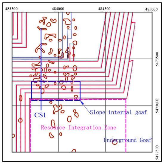
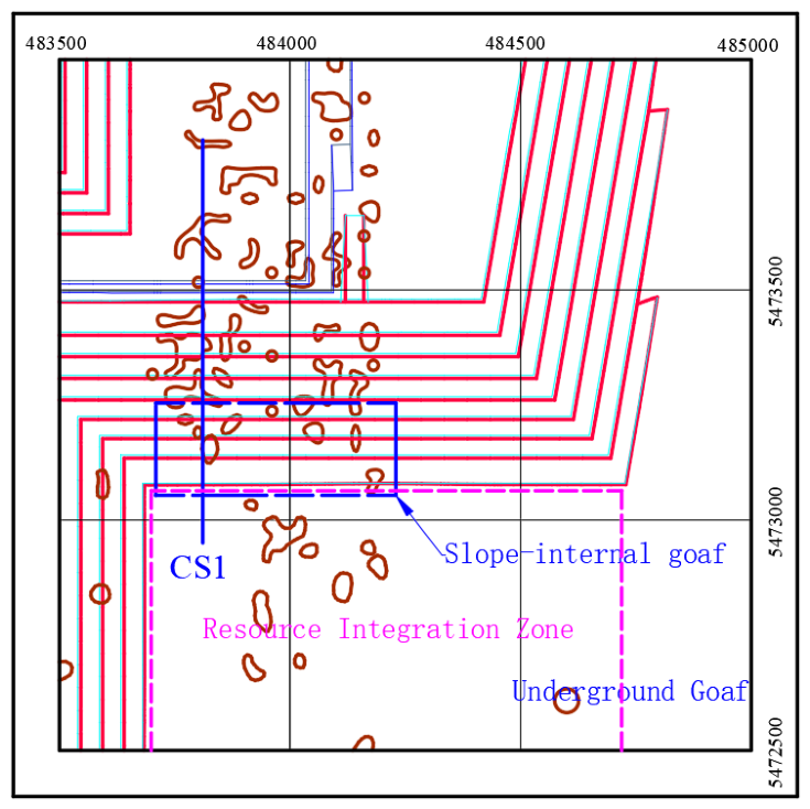
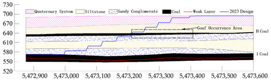
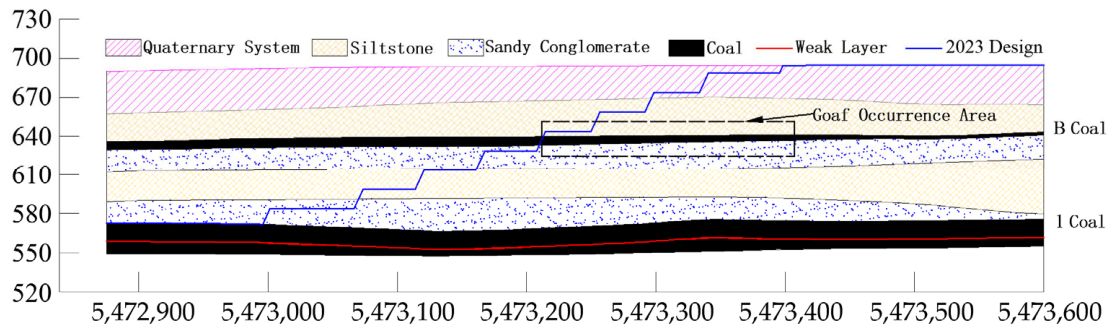
Due to the long mining history and the occurrence of disorderly mining activities prior to resource integration, a substantial number of undocumented goafs remain within the mining area. In 2020, Zhongcai Geological Engineering Exploration and Research Institute Co., Ltd. conducted precise goaf detection in the resource integration area using advanced exploration techniques including the 3D seismic method, the high-density electrical method, and the transient electromagnetic method. The exploration revealed that the goafs are predominantly located within the resource integration area and in the southern slope north of this area, specifically at the B coal seam. The distribution of goafs within the slope is illustrated in Figure 1. A typical cross-section CS1 was selected perpendicular to the strike direction of the southern slope, with its sectional morphology shown in Figure 2.
Figure 1.
Distribution plan of goaf in slope.
Figure 2.
Section of CS1.
3. Analysis of the Influence Mechanism of Goaf on Slope Stability
3.1. Theoretical Basis of Overburden Deformation Zoning and Empirical Height Estimation
After underground coal extraction, removal of the supporting coal mass disturbs the original stress equilibrium of the overburden and induces a vertically differentiated deformation response. According to the degree of structural disruption and deformation, the mining-affected overburden can be conceptually divided into three characteristic zones: the caving zone, fractured zone, and bending-subsidence zone. This three-zone framework provides the mechanical basis for describing how mining-induced damage propagates upward from the goaf and for assigning spatially differentiated mechanical properties in the subsequent slope-stability analysis.
The caving zone occurs immediately above the goaf, where the loss of support causes roof strata to fracture, detach, rotate, and collapse into the mined-out void. Above it, the fractured zone is characterized by pronounced mining-induced cracking, bed separation, and relative movement between adjacent strata, although the original stratigraphic sequence is still partly preserved. At greater elevations, the overburden enters the bending-subsidence zone, where the strata generally retain their continuity and deform predominantly through coordinated bending and settlement rather than complete structural breakage. The boundaries between these zones are therefore associated with different degrees of rock-mass discontinuity, relative displacement, and loss of structural integrity.
The deformation and failure characteristics of the overburden are closely related to the geometric characteristics of the underground goaf. Variations in goaf width, mining height, and inter-goaf spacing influence the spatial extent of mining-induced deformation and the development of the overburden failure zones. An empirical extraction-degree criterion reported in Ref. [17] relates the extent of underground extraction to the average mining depth and can be used as a general reference for distinguishing incomplete and more extensive mining disturbance. However, because this criterion was developed from generalized mining conditions and was not specifically calibrated for the geological and geometric conditions of the present open-pit slope, it is not treated here as a strict site-specific threshold. In the present study, the final interpretation of the extraction condition is based primarily on the deformation characteristics obtained from the 3DEC simulations. Cases in which only caving and fractured zones develop are interpreted as incomplete-extraction conditions, whereas the development of a distinct bending-subsidence zone above the fractured zone indicates a more fully developed three-zone overburden response.
Following underground coal extraction, the original mechanical equilibrium of the roof strata is disturbed. Rock strata immediately above the goaf progressively fracture and cave into the mined-out void, and the caving process propagates upward until the available void space is substantially filled by collapsed rock fragments. According to the relevant empirical relationships adopted in the original study and the laboratory-derived mechanical properties of the roof rock, the representative fine sandstone in the roof has a compressive strength of approximately 10–20 MPa. The heights of the caving and fractured zones can be estimated using empirical relationships established from mining observations and overburden conditions. These relationships are not governing equations derived specifically for the present numerical model; rather, they provide engineering estimates for the expected vertical extent of mining-induced overburden failure. In this study, the empirical relationships reported in Ref. [18] are adopted as independent reference estimates because they relate deformation-zone height primarily to cumulative mining thickness and the corresponding roof-rock conditions. The coefficients appearing in the equations are empirical coefficients adopted directly from the cited relationship and were not fitted to the present 3DEC results.
where HA is the estimated height of the caving zone (m), and ∑M is the cumulative mining thickness (m). The numerical coefficients 6.2 and 32 are empirical constants contained in the relationship adopted from Ref. [18], while ±1.5 m represents the empirical deviation range associated with this estimate. These coefficients are therefore not material constants and were not calibrated using the numerical results of the present study.
Above the caving zone, mining-induced fractures develop progressively upward as the extraction area expands. The height of the fractured zone generally increases with the enlargement of the mining area and approaches a maximum when the mining disturbance reaches a sufficiently large spatial extent. As overburden movement gradually stabilizes with time, some fractures in the upper part of the fractured zone may progressively close, resulting in a corresponding reduction in the effective fractured-zone height. The fractured zone develops above the caving zone as mining-induced tensile and shear fractures propagate upward while the strata retain a greater degree of structural continuity than those in the caving zone. Its height was estimated using the corresponding empirical relationship reported in Ref. [18]:
where HL is the estimated height of the fractured zone (m). The coefficients 3.1 and 5.0 are the empirical coefficients of the relationship adopted from Ref. [18], and ±4.0 m represents its empirical deviation range. As with Equation (1), these coefficients were not obtained by fitting the numerical results of the present study.
The empirical equations adopted above were selected according to the roof-rock characteristics and the laboratory-derived mechanical properties of the investigated mine. Because empirical relationships are derived from generalized geological and mining conditions, their predictions should be regarded as reference estimates rather than exact representations of the site-specific boundaries of the overburden deformation zones. Therefore, their applicability to the investigated mine was further examined by comparing the calculated values with the 3DEC numerical results.
The mining height of the historical goaf investigated in this study is approximately 2.0 m. Substituting ΣM = 2.0 m into Equations (1) and (2) gives a caving-zone height of approximately 4.50 ± 1.50 m and a fractured-zone height of approximately 17.86 ± 4.00 m. The corresponding empirical ranges are therefore approximately 3.00–6.00 m for the caving zone and 13.86–21.86 m for the fractured zone.
For the 50 m wide single-goaf case, in which the numerical model reaches the full-extraction condition, the 3DEC simulation gives a caving-zone height of 3.8 m and a fractured-zone height of 13.0 m. The simulated caving-zone height falls within the empirical range of 3.00–6.00 m. The simulated fractured-zone height is slightly lower than the lower empirical bound of 13.86 m, with a difference of approximately 0.86 m. Overall, the empirical and numerical approaches provide comparable estimates of the scale of mining-induced overburden failure. The remaining difference can be attributed to the generalized nature of the empirical relationships, whereas the 3DEC model explicitly incorporates the stratigraphic configuration and mechanical parameters adopted for the study area.
Accordingly, the empirical equations are used in this study as independent reference estimates for assessing the physical reasonableness of the numerical results rather than as exact predictions of the deformation-zone boundaries. The final heights and spatial extents of the overburden deformation zones used in the subsequent slope-stability analysis are determined from the 3DEC simulations. Accordingly, Equations (1) and (2) are used only to establish an expected engineering range for the caving- and fractured-zone heights and to provide an independent consistency check for the 3DEC simulations. They are not used to prescribe the deformation-zone geometry in the numerical model. The final heights and spatial extents adopted in the subsequent slope-stability calculations are determined from the 3DEC results.
The bending-subsidence zone develops above the fractured zone when sufficiently extensive mining-induced deformation occurs. Compared with the caving and fractured zones, the strata within the bending-subsidence zone generally retain greater structural continuity and undergo predominantly coordinated bending and subsidence. In a vertical section, the difference in subsidence between the upper and lower parts of the bending-subsidence zone is relatively small. Bed separation rarely occurs in its upper part but may locally develop near its lower boundary. These separation fractures are generally localized and are not connected with the underlying water-conducting fractured zone [19].
3.2. Analysis of Landslide Modes Under Goaf Influence
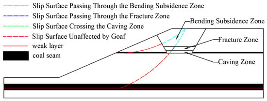
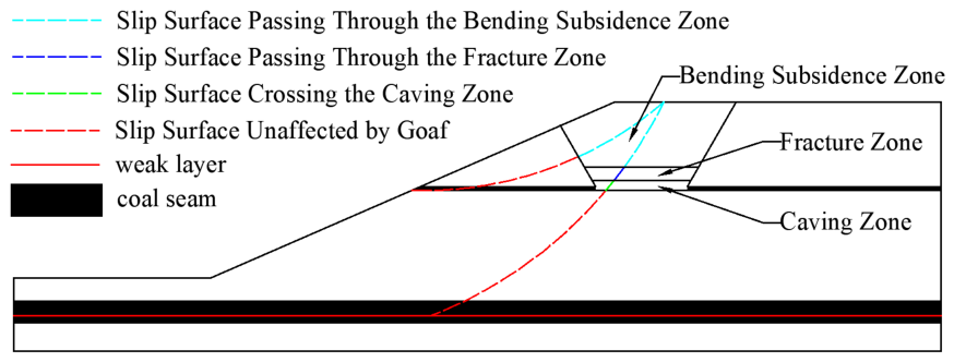
Under the combined influence of goafs and open-pit mining, the slope experiences not only collapse failure of the overlying rock mass along certain boundaries [20], but also slip failure along specific sliding surfaces. Since the south slope of the open-pit coal mine in Inner Mongolia contains multiple goafs, and some potential sliding surfaces are located within the subsidence displacement range, the resulting failure mode may be characterized as a composite slip-subsidence failure mode.
Based on the morphology of the sliding surface, the potential failure modes of the slope can be classified as circular sliding or composite sliding. In the subsequent stability analysis, these two modes are treated as competing deterministic failure modes. Under the same goaf condition, the mode with the lower calculated factor of safety is regarded as the more critical potential failure mode. This comparison is intended to identify the mechanically controlling failure mode and does not represent a probabilistic estimate of the likelihood of failure. In such cases, the potential sliding surface located within the subsidence zone traverses various sub-zones (caving zone, fractured zone, and bending zone). When employing the limit-equilibrium theory to analyze slope stability, it is necessary to assign segmented parameters to the divided slices. Since the proportional length of each sub-zone within a slice is not uniform, and the strength of each sub-zone is lower than that of the intact rock mass, the height of the “three zones”, the boundary movement angle, and the reduced strength of each sub-zone must be determined prior to analyzing the slope stability. A schematic diagram of the slip-subsidence failure mode is shown in Figure 3.
Figure 3.
Slip-collapse failure mode.
4. Numerical Simulation Study on the Movement Law of Overlying Strata in Goaf
The 3DEC 5.2 numerical simulation software employs the discrete element method (DEM) for its calculations [21]. During the simulation process, plastic displacements occur between the divided blocks. When sufficient space for displacement exists, separation between blocks will occur. When conducting numerical analysis of goaf roof collapse, this method yields relatively ideal computational results that align well with actual collapse patterns, thereby enabling effective analysis of the displacement and deformation characteristics of the overlying strata in the goaf area.
4.1. Numerical Model and Boundary Conditions
A three-dimensional discrete-element model was established using 3DEC based on the representative CS1 cross-section of the southern slope. The model was designed to investigate the development characteristics of mining-induced overburden deformation above both single and adjacent goafs. Considering the geological configuration of the study area and computational efficiency, the model dimensions were set to 300 m × 5 m × 120 m.
The computational domain was selected to reproduce the representative CS1 geological section while retaining sufficient surrounding rock mass around the modeled underground workings and the principal mining-induced deformation region. The model boundaries were positioned outside the main region of interest so that the analysis focused on the deformation response above and around the goafs rather than on deformation immediately adjacent to the constrained boundaries. The selected domain therefore represents a practical compromise between reproducing the field-scale geological configuration and maintaining computational efficiency. A formal domain-size sensitivity analysis was not performed in the present study; therefore, the possibility of some residual influence of the computational boundaries cannot be completely excluded.
The geometrical configuration of the historical underground workings was constrained using the results of the goaf investigation conducted in 2020. Three-dimensional seismic surveying, high-density electrical resistivity surveying, and transient electromagnetic surveying were used to identify the distribution of the historical goafs within the resource-integration area and the southern slope. According to these investigation results, the representative mining height of the goaf was set to 2.0 m. Because the ground surface varies along the slope profile, the cover thickness above the B-seam goaf is spatially variable. Therefore, the classification of the simulated cases is based primarily on the development characteristics of the overburden deformation zones rather than on a single constant width-to-depth ratio.
Four goaf widths of 20, 30, 40, and 50 m were considered in the numerical analysis. For the double-goaf models, four inter-goaf spacings of 10, 30, 50, and 70 m were investigated to evaluate the interaction between adjacent underground workings.
The block discretization was established according to the principal stratigraphic boundaries represented in the CS1 geological section so that the layered structure of the coal-bearing strata and the interfaces controlling mining-induced deformation could be explicitly represented in the 3DEC model. A consistent discretization strategy was maintained for all parametric cases to ensure comparability among simulations with different goaf widths and inter-goaf spacings. The adopted discretization was intended to provide sufficient geometric resolution for representing block separation, contact deformation, and mining-induced roof movement while maintaining a computationally manageable model. A formal block-size convergence analysis was not conducted; therefore, the calculated deformation-zone dimensions should be interpreted primarily in terms of the relative trends among the investigated cases rather than as strictly mesh-independent absolute predictions.
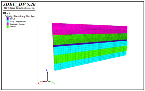
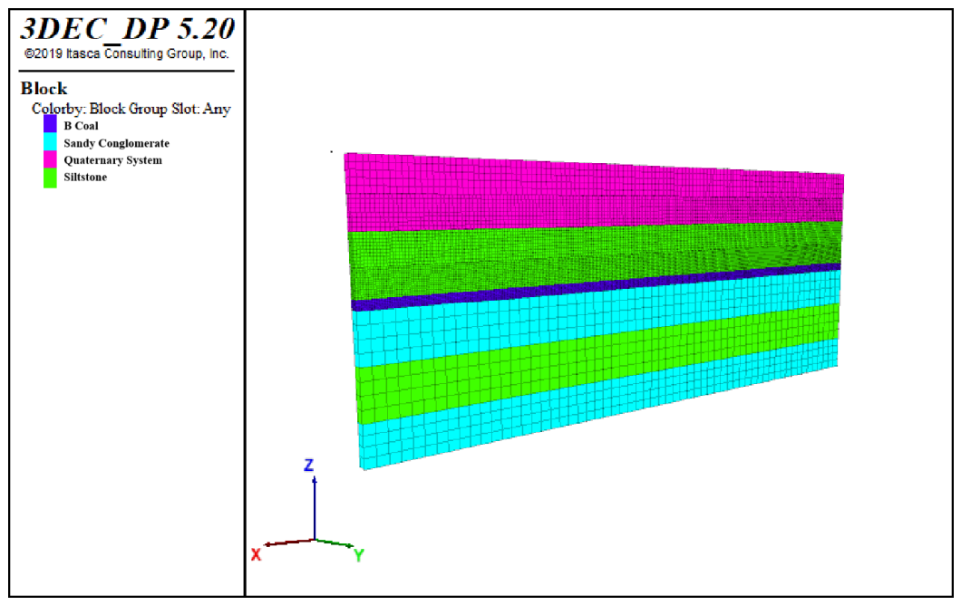
The rock mass was represented using the Mohr–Coulomb constitutive model. This model was adopted because the primary objective of the present simulations is to characterize the spatial development and relative variation in mining-induced overburden deformation zones under different goaf configurations rather than to reproduce the complete post-peak stress–strain evolution of the rock mass. The mechanical data available for the study area mainly include elastic parameters, cohesion, friction angle, and tensile strength obtained from laboratory testing, direct shear testing, and parameter reduction, which can be directly incorporated into the Mohr–Coulomb framework. In contrast, a strain-softening model requires additional site-specific relationships describing the evolution of strength parameters with accumulated plastic strain. Such post-peak data are not available for the investigated rock masses, and introducing assumed softening laws without experimental calibration would add additional uncertainty to the numerical analysis. Therefore, the Mohr–Coulomb model was considered appropriate for the comparative parametric analyses performed in this study, while its limitations in representing progressive post-peak degradation are acknowledged below. The lateral boundaries in the x- and y-directions and the bottom boundary were constrained, whereas the top surface was left free. Under the natural condition considered in this study, the initial stress field was generated primarily by the self-weight of the overlying materials. The numerical analysis was formulated as a mechanical model and did not explicitly include groundwater flow, pore-water pressure, rainfall infiltration, or seasonal variations in rock moisture. This assumption was adopted to isolate the mechanical influence of underground goaf geometry on overburden deformation and slope stability. The numerical model and stratigraphic configuration are shown in Figure 4.
Figure 4.
Numerical calculation model.
4.2. Model Verification and Engineering Consistency Assessment
The physical and mechanical parameters adopted in the numerical model were determined from laboratory testing, direct shear testing, parameter reduction, and previously established parameter-selection methods. Representative samples corresponding to the principal lithological units were used in the laboratory characterization, while the shear-strength parameters of the discontinuities were evaluated using direct shear testing. The laboratory-derived parameters were subsequently adjusted to account for the difference between intact or small-scale specimens and field-scale rock masses. The resulting parameters were then combined with previously established parameter-selection procedures to determine the values adopted in the numerical model. Because detailed original test records are not available for all historical datasets used in this engineering study, the manuscript does not attempt to reproduce complete specimen-preparation and loading procedures; instead, the parameter sources and subsequent field-scale adjustment procedures are explicitly stated. Because laboratory measurements obtained from intact or relatively small rock specimens may overestimate the mechanical strength of field-scale rock masses, the cohesion and internal friction angle were appropriately reduced according to the strength-reduction relationships reported in previous studies [22]. The strength parameters of the discontinuities were constrained primarily by direct shear test results, whereas the normal and shear stiffnesses used for the block contacts were estimated using the stiffness-parameter selection procedure reported in Ref. [23] together with the mechanical characteristics of the corresponding strata. Because direct field measurements of joint stiffness were unavailable for the investigated open-pit slope, the adopted normal and shear stiffness values were not calibrated against in situ monitoring data. Instead, these parameters were selected as equivalent engineering parameters based on published studies and adjusted according to the lithological characteristics of the studied rock mass. In the 3DEC model, the joint stiffness values mainly control the deformation compatibility and stress transfer behavior between adjacent blocks rather than representing unique intrinsic properties of natural discontinuities. Thus, the stiffness values listed in Table 1 hould be interpreted as finite equivalent contact stiffnesses adopted for the numerical representation of the discontinuities rather than as rigid-contact parameters. The adopted normal and shear stiffnesses range from 0.03 to 0.50 GPa/m and from 0.01 to 0.19 GPa/m, respectively. These values allow relative normal deformation and shear displacement to develop along the contacts during mining-induced overburden movement. The resulting rock-mass and joint parameters used in the numerical model are summarized in Table 1 and Table 2, respectively.
Table 1.
Mechanical indexes of joints.
Table 2.
Physical and mechanical indexes of rock and soil mass.
The geological geometry of the model was independently constrained by the field investigation of historical goafs. In 2020, three-dimensional seismic, high-density electrical resistivity, and transient electromagnetic surveys were conducted in the study area to identify the distribution and occurrence of the underground workings. These investigation results were used to define the representative goaf location and mining height and to establish the numerical geometry based on the CS1 cross-section.
Direct field measurements of the internal boundaries of the caving and fractured zones are not available in the current dataset because the investigated goafs were formed during historical underground mining. Therefore, the 3DEC model cannot be fully calibrated against direct measurements of the internal overburden deformation zones. To provide an independent consistency check, the numerical results were compared with the empirical estimates described in Section 3.1.
For a mining thickness of 2.0 m, the empirical equations predict a caving-zone height of approximately 4.50 ± 1.50 m and a fractured-zone height of approximately 17.86 ± 4.00 m. For the 50 m wide single-goaf model, in which a complete caving–fractured–bending-subsidence zonation develops, the corresponding 3DEC values are 3.8 m and 13.0 m, respectively. The simulated caving-zone height falls within the empirical range, whereas the fractured-zone height is slightly below the lower empirical estimate. Nevertheless, the numerical and empirical approaches predict a comparable overall scale of overburden failure. However, this comparison should not be interpreted as a validation of either the empirical relationships or the absolute accuracy of the 3DEC model. The empirical equations were derived from generalized mining conditions and were not specifically calibrated for the geological conditions of the investigated mine. Therefore, the comparison only demonstrates that the numerical results fall within a reasonable engineering magnitude range.
The model assessment adopted in this study therefore consists of three complementary components: geological constraint, mechanical parameter determination, and engineering consistency evaluation with empirical deformation-zone estimates. The lack of direct field measurements of the internal deformation-zone boundaries is recognized as a limitation of the present study. These comparisons indicate that the numerical results are within the same order of magnitude as empirical estimations, providing an independent engineering consistency assessment of the predicted deformation-zone development. However, this comparison should not be interpreted as a direct validation of the empirical relationships or the absolute accuracy of the numerical model, because the empirical equations were developed from generalized mining conditions and were not specifically calibrated for the geological characteristics of the investigated deposit. In this study, the boundaries between different deformation zones were not determined by a single predefined displacement or contact-opening threshold. Instead, they were identified based on the combined characteristics of displacement distribution, relative block movement, contact separation, and deformation continuity. The caving zone was characterized by intense block separation and concentrated contact opening, whereas the fractured zone was identified by continuous development of relative displacement and interconnected opening patterns. The bending-subsidence zone corresponded to areas dominated by continuous deformation without significant block separation. The joint stiffness parameters represent equivalent contact properties adopted for discontinuous deformation analysis and should not be directly interpreted as laboratory-scale fracture stiffness values.
4.3. Analysis of Numerical Simulation Results for a Single Goaf
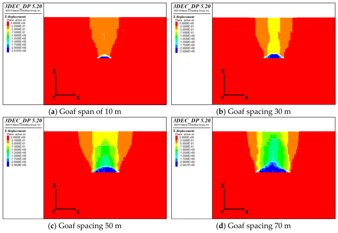
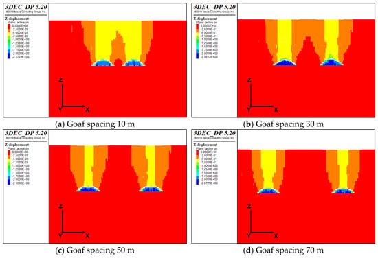
For the 20 m wide goaf, the simulated roof response is characterized mainly by the development of caving and fractured zones, and no distinct bending-subsidence zone is observed. When the goaf width increases to 30 m, the extent of the mining-induced displacement field increases, although the overburden response remains dominated by the caving and fractured zones. At a goaf width of 40 m, the displacement field expands markedly upward and laterally, indicating a transition toward more extensive overburden disturbance. When the goaf width increases to 50 m, a distinct bending-subsidence zone develops above the fractured zone, resulting in the formation of the complete caving–fractured–bending-subsidence zonation in the numerical model. The lateral displacement field also continues to develop upward, with the upper boundary of the disturbed region approaching the ground surface. The vertical displacement contours of the single-goaf models are shown in Figure 5.
Figure 5.
Vertical displacement cloud map of the single goaf.
Analysis of the calculation results from the single goaf model reveals that, under the influence of roof collapse in the single goaf, when full mining conditions are not satisfied, the height of the caving zone shows an increasing trend with the expansion of the goaf span, while the boundary movement angle exhibits a decreasing trend. Under these conditions, only the caving zone and fractured zone are present in the roof strata. When the goaf meets the full mining conditions, both the height of the caving zone and the boundary movement angle reach their extreme values, and the “three-zone” structure emerges in the overlying strata. A summary of the numerical simulation results for the single goaf is presented in Table 3.
Table 3.
Summary of single-goaf numerical simulation results.
4.4. Analysis of Numerical Simulation Results for Double Goafs
(1) Goaf Span of 20 m
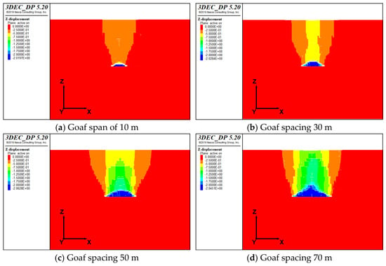
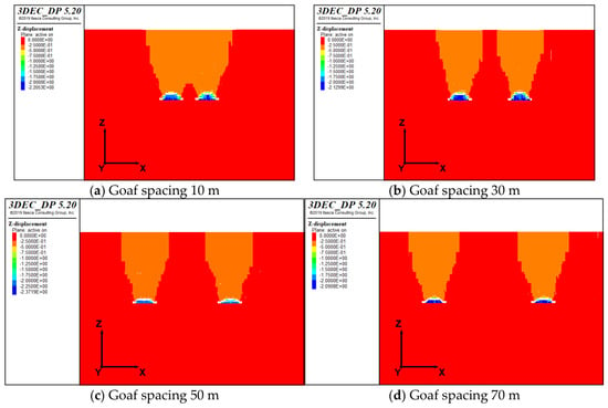
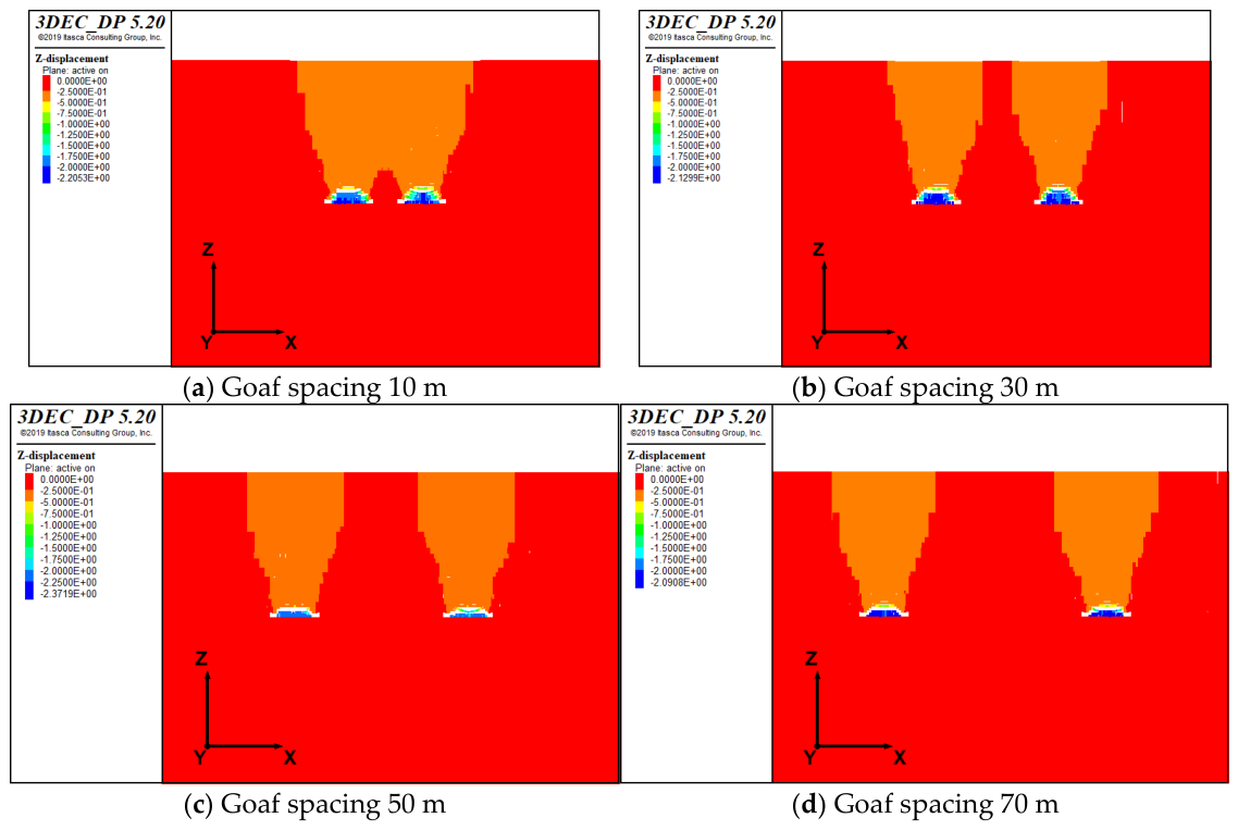
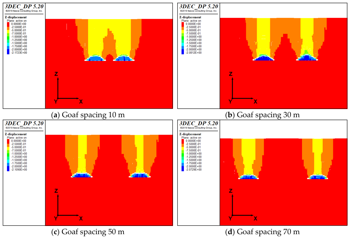
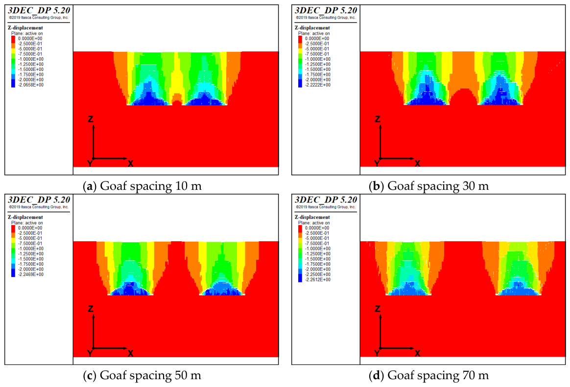
Since the span-to-depth ratio of the 20 m goaf is far from satisfying the full mining conditions, the overlying strata still do not develop a bending subsidence zone. When the spacing between goafs is less than 30 m, the influence of adjacent goafs results in a greater height of the caving zone in double goafs compared to a single goaf. At inter-goaf spacings of 50 and 70 m, the simulated caving-zone heights are 3.0 and 3.2 m, respectively, which are close to the value of 3.0 m obtained for the corresponding single-goaf model. This indicates that the interaction between adjacent goafs becomes relatively weak for the 20 m wide goaf case as the spacing increases. The vertical displacement cloud map of the double goaf model with a 20 m span is shown in Figure 6.
Figure 6.
Vertical displacement cloud map of double goaf with 20 m spacing.
(2) Goaf Span of 30 m
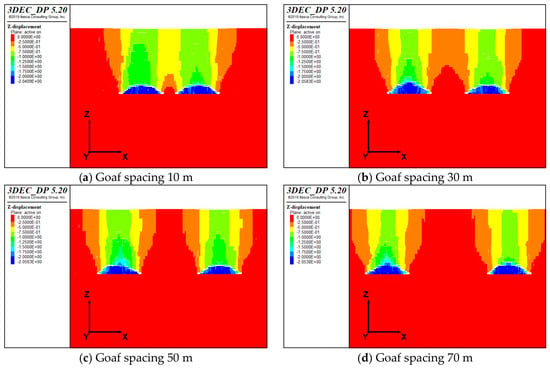
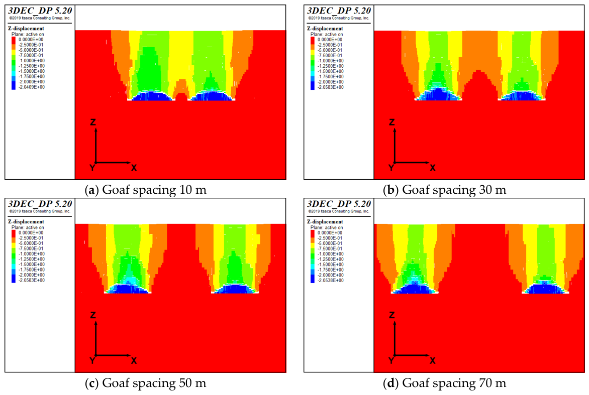
Although this goaf span still does not satisfy the full mining requirements, the influence of adjacent goaf collapse causes bed separation phenomena in the rock strata overlying the caving zone. The morphological structure of these separated strata resembles that of a fractured zone, but with a height significantly less than that of a true fractured zone. Based on the morphological characteristics of the rock mass, this feature is termed a “pseudo-fractured zone”. The pseudo-fractured zone represents a transitional deformation region characterized by localized bed separation and crack development, but without the continuous fracture connectivity and extensive structural disturbance required to define a fully developed fractured zone. Therefore, it is regarded as an intermediate deformation state between the caving zone and the fractured zone rather than an independent deformation zone. Within the caving deformation area, vertical displacement overlap occurs in the roof of the double goafs. As the spacing between goafs increases, the influence of adjacent goaf collapse behavior gradually diminishes, resulting in a corresponding reduction in the area of displacement overlap. This trend continues until the collapse behaviors of the double goafs become mutually independent. The vertical displacement cloud map of the double goaf model with a 30 m span is shown in Figure 7.
Figure 7.
Vertical displacement cloud map of double goaf with 30 m spacing.
(3) Goaf Span of 40 m
For the 40 m wide double-goaf cases, the caving-zone height increases to approximately 6.4–7.4 m, which is noticeably greater than the range of approximately 3.8–4.4 m obtained for the 30 m wide cases. This increase reflects a transition in the simulated roof-collapse pattern rather than a simple linear increase with goaf width. In the 30 m wide cases, part of the mining-induced deformation is accommodated by localized bed separation above the caving zone, forming the pseudo-fractured zone described above. When the goaf width increases to 40 m, the larger disturbed roof span and stronger interaction between the deformation fields of adjacent goafs promote more direct downward collapse of the roof strata, resulting in a greater vertical extent of the caving zone. The mean caving-zone heights for the 30, 40, and 50 m wide double-goaf cases are approximately 4.15, 6.65, and 6.70 m, respectively. This indicates that the major change occurs between the 30 and 40 m cases, after which the caving-zone height remains at a comparable scale. Therefore, the 40 m case is interpreted as a transitional collapse configuration within the investigated numerical conditions rather than as an isolated numerical anomaly. The vertical displacement cloud map of the double goaf model with a 40 m span is shown in Figure 8.
Figure 8.
Vertical displacement cloud map of double goaf with 40 m spacing.
(4) Goaf Span of 50 m
The span-to-depth ratio of this goaf satisfies the full mining conditions, resulting in complete collapse of the goaf roof. A distinct fracture development zone is observed above the caved rock-mass accumulation, and the “three-zone” structure appears in the overlying strata. Influenced by the collapse of adjacent goafs, displacement overlap zones also exist in the overlying strata of the goaf, following the same variation pattern with goaf span as observed in the 30 m and 40 m span goafs. The lateral displacement zone continues to develop upward, and the magnitude of lateral displacement increases with the enlargement of goaf spacing. The caving zone shows significant enhancement compared to the single goaf scenario. When the goaf spacing is less than 30 m, the height of the fractured zone increases markedly relative to the single goaf. As the inter-goaf spacing increases, the influence of adjacent-goaf interaction on the fractured-zone development generally decreases. At a spacing of 50 m, the fractured-zone height is 13.2 m, which is close to the 13.0 m obtained for the corresponding single-goaf case. However, the value increases to 15.2 m at a spacing of 70 m, indicating that the response is not strictly monotonic and that a universal critical spacing cannot be identified from the present discrete simulations. The vertical displacement cloud map of the double goaf model with a 50 m span is shown in Figure 9.
Figure 9.
Vertical displacement cloud map of double goaf with 50 m spacing.
Analysis of the double-goaf simulations shows that the interaction between adjacent goafs is strongly dependent on both goaf width and inter-goaf spacing. At relatively small spacings, the deformation fields generated by adjacent goafs overlap, resulting in enhanced roof deformation and, in several cases, greater development of the caving or fractured zones compared with the corresponding single-goaf condition. For the 30 m wide goaf, the interaction between adjacent workings also produces a locally developed separation zone above the caving zone, which is referred to here as a pseudo-fractured zone.
As the inter-goaf spacing increases, the overlap between the deformation fields generally decreases and the influence of adjacent goafs tends to weaken. However, the numerical results do not support defining 50 m as a universal critical spacing. The degree to which the double-goaf results approach those of the corresponding single-goaf model varies with goaf width and with the response parameter considered. For example, some cases show relatively small differences in fractured-zone height or boundary movement angle at spacings of 50–70 m, whereas noticeable differences in caving-zone height remain for the larger goaf-width cases.
Therefore, the spacing of approximately 50 m identified from the present simulations should be interpreted only as a site-specific transition range within the discrete cases investigated, rather than as a universal threshold beyond which adjacent-goaf interaction becomes negligible. Additional simulations with smaller spacing increments and uncertainty analysis would be required to determine a statistically robust critical spacing. A summary of the numerical simulation results for the double-goaf cases with different goaf widths and inter-goaf spacings is presented in Table 4.
Table 4.
Summary of double-goaf numerical simulation results.
The results further indicate that the caving-zone response is nonlinear with respect to goaf width. In particular, the marked increase between the 30 and 40 m cases reflects a change in the dominant roof-deformation pattern, whereas the mean caving-zone heights of the 40 and 50 m cases remain comparable.
5. Slope Stability Analysis and Evaluation of an Open-Pit Coal Mine with Goafs in Inner Mongolia
Following the collapse of the goaf roof, the physical and mechanical properties of the rock mass within the “three zones” of the overlying strata are reduced compared to the laboratory test data. Extensive field tests conducted by the Chongqing Rock Foundation Research Center of the Changjiang River Scientific Research Institute indicate that the internal friction angle differs only slightly between the “three zones”, while the cohesion undergoes significant changes [24]. The caving zone, consisting of loose and re-compacted coal and rock mass, also exhibits a reduction in unit weight compared to the intact rock mass. Consequently, the aforementioned parameters were reduced accordingly, and the summarized results are presented in Table 5.
Table 5.
Mechanical parameters assigned to different overburden deformation zones after goaf-induced degradation.
The heights of the “three zones” in the overlying strata and the boundary movement angle were obtained through numerical simulation methods. By integrating the aforementioned data with the typical cross-section of the southern slope north of the resource integration area, and considering the spatial distribution of goafs within the slope, the slope stability under the influence of goafs was analyzed using the Morgenstern–Price method [25]. The goaf occurrence characteristics include span, mining height, spatial location, and spacing. According to the geophysical prospecting results of goafs in the resource integration area of the open-pit coal mine in Inner Mongolia, the mining height of the goafs is essentially identical. Therefore, the variation patterns between slope stability and three key parameters—goaf span, spatial location, and goaf spacing—were analyzed systematically.
5.1. Goaf Span
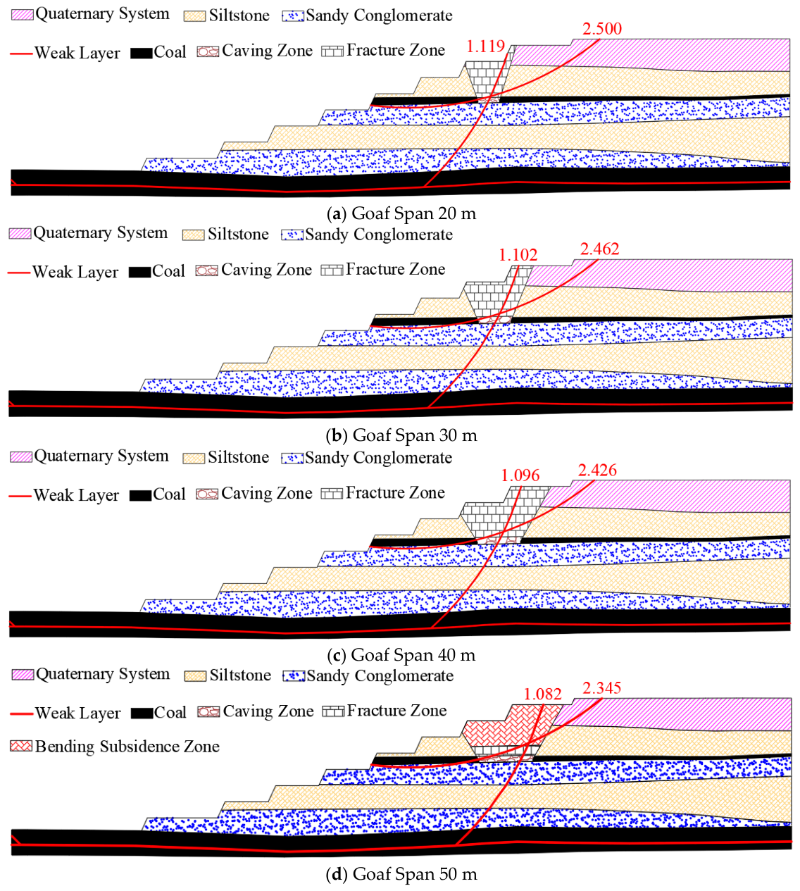
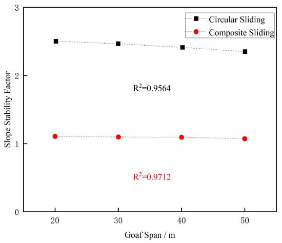
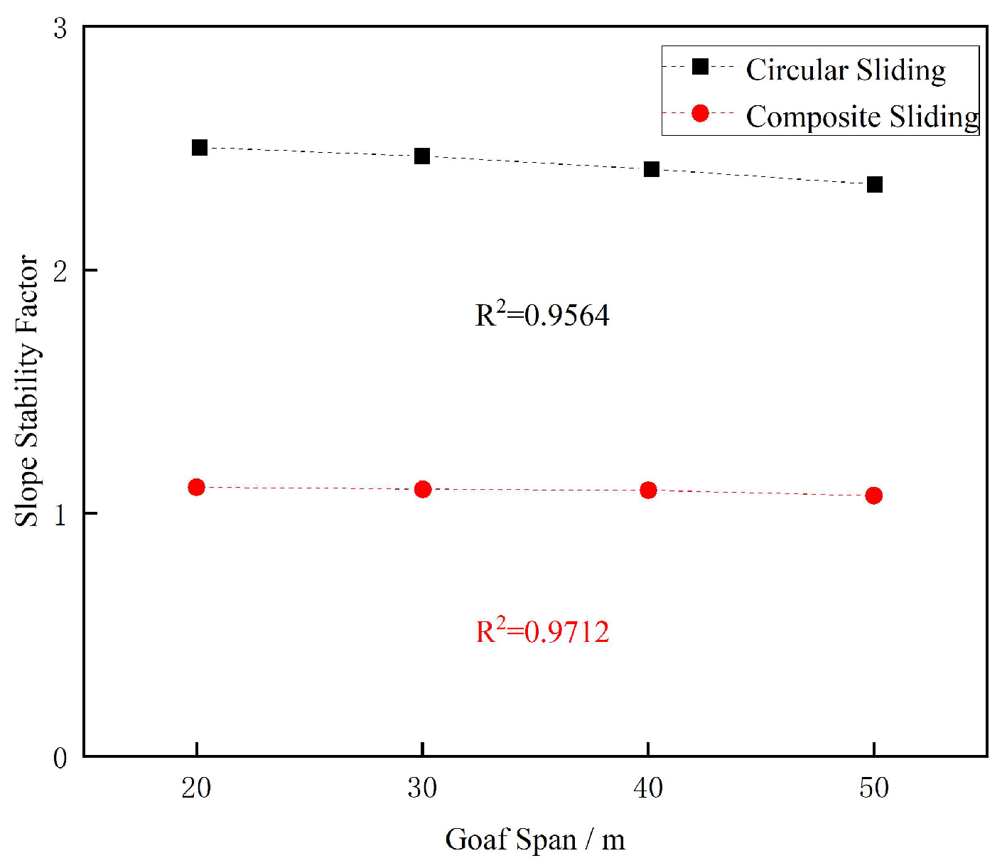
It is assumed that the horizontal distance between the goaf and the slope is 100 m, and the selected sliding surfaces all pass through the three zones. Four groups of goaf spans (20 m, 30 m, 40 m, and 50 m) were selected to analyze the variation pattern with slope stability. The potential landslide modes of the slope include circular sliding or composite sliding with the weak layer of Coal 1 as the bottom interface. When circular sliding occurs, the slope stability factors are 2.500, 2.462, 2.426, and 2.345, respectively. When composite sliding occurs, the slope stability factors are 1.119, 1.102, 1.096, and 1.082, respectively. The calculated sliding surfaces and corresponding factors of safety for the four goaf-width cases are shown in Figure 10. Within the investigated goaf-width range of 20–50 m, the factors of safety for both potential failure modes exhibit an approximately linear decreasing trend with increasing goaf width. Linear regression gives R2 values of 0.9564 and 0.9712 for circular and composite sliding, respectively. The relationship between goaf width and the factor of safety for the two potential failure modes is illustrated in Figure 11. These regressions describe the response of the four deterministic cases investigated and should not be interpreted as a universal linear relationship between goaf width and slope stability. For the four goaf-width cases, the factor of safety for composite sliding is approximately 53.9–55.2% lower than that for circular sliding. Therefore, according to the deterministic factor-of-safety criterion adopted in this study, the weak-interlayer-controlled composite sliding mode represents the more critical potential failure mode under the investigated goaf-width conditions.
Figure 10.
Diagram of calculation results of goaf span.
Figure 11.
Variation curve of goaf span and slope stability.
5.2. Occurrence Location of Goaf Occurrence
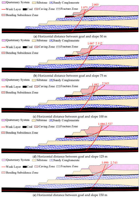
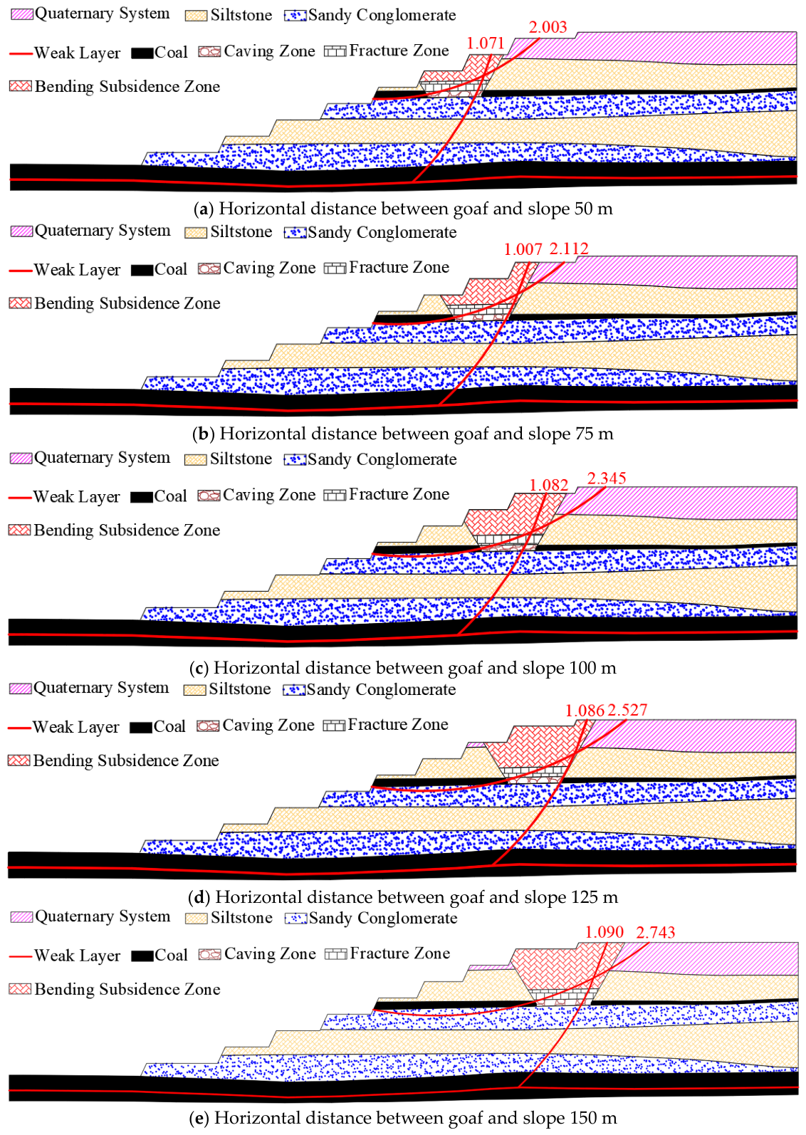
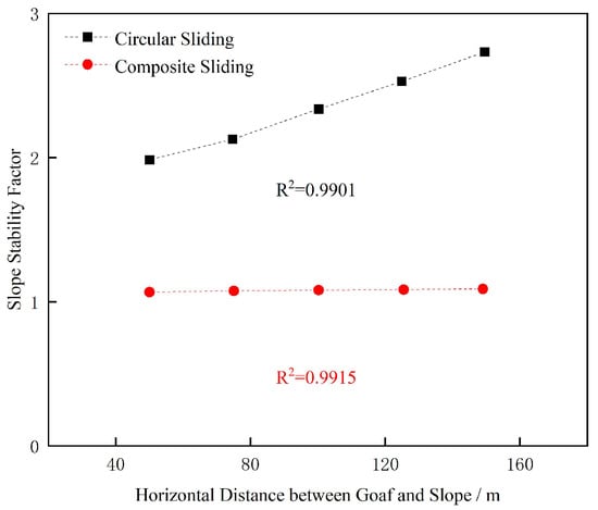
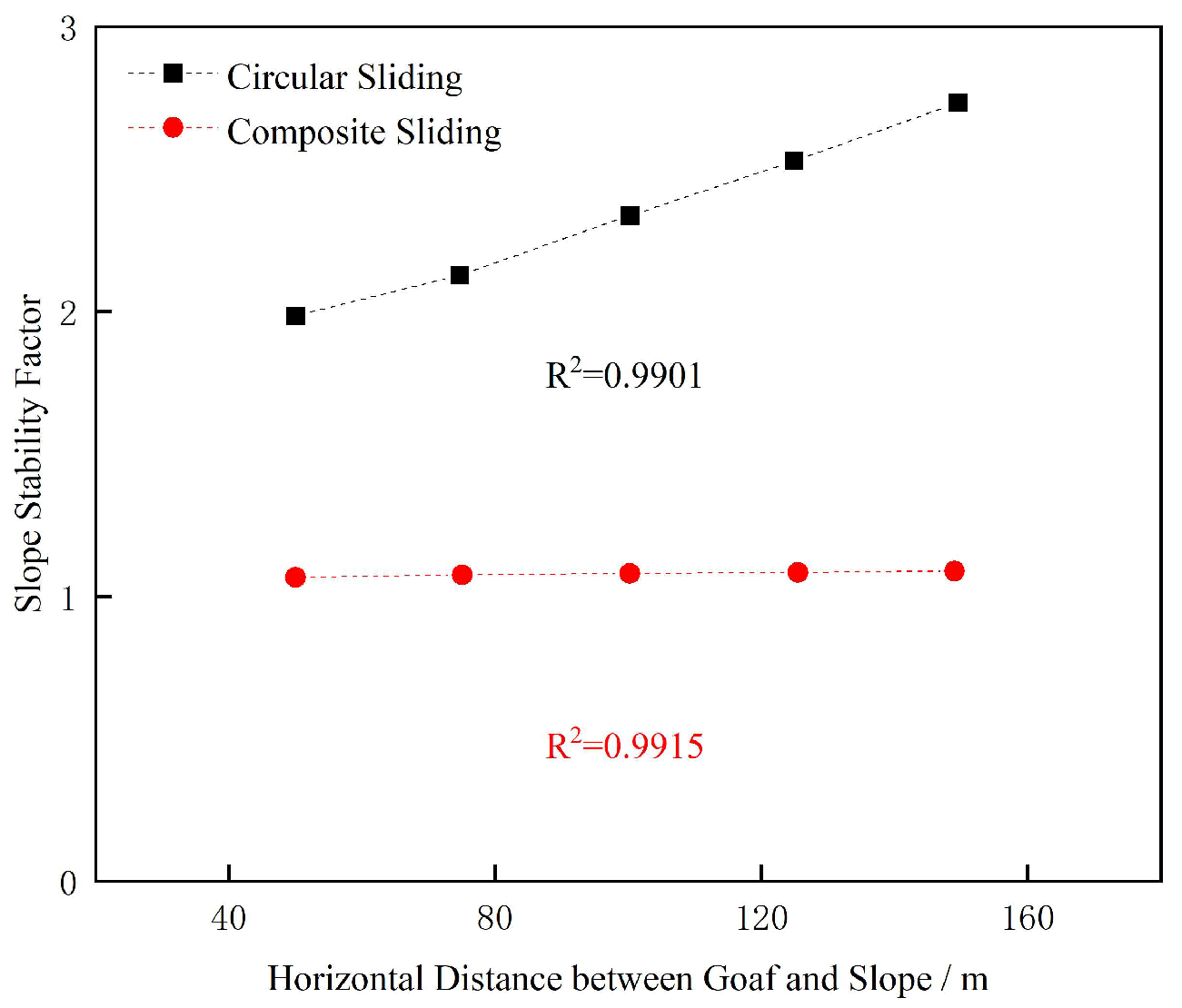
Assuming a goaf span of 50 m, with a caving zone height of 3.8 m and a fractured zone height of 13.0 m, the selected sliding surfaces all pass through the three zones. The spatial location of the goaf was characterized by the horizontal distance between the goaf and the slope, with five datasets selected to analyze its influence on slope stability: 50 m, 75 m, 100 m, 125 m, and 150 m. When circular sliding occurs, the slope stability factors are 2.003, 2.113, 2.345, 2.527, and 2.743, respectively. For composite sliding scenarios, the corresponding stability factors are 1.071, 1.077, 1.082, 1.086, and 1.090, respectively. As the horizontal distance between the goaf and the slope increases, the slope stability factors under both landslide modes exhibit a linear increasing trend. Across the five goaf-location cases, the factor of safety for composite sliding is approximately 46.5–60.3% lower than that for circular sliding. Therefore, based on the deterministic factor-of-safety comparison, composite sliding remains the more critical potential failure mode within the investigated range of goaf locations. The calculation results are shown in Figure 12, while the influence of goaf spatial location on slope stability is illustrated in Figure 13.
Figure 12.
Diagram of calculation results of goaf location.
Figure 13.
Variation curve of goaf location and slope stability.
5.3. Goaf Spacing
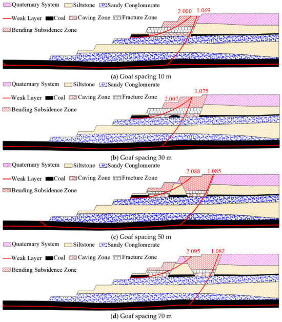
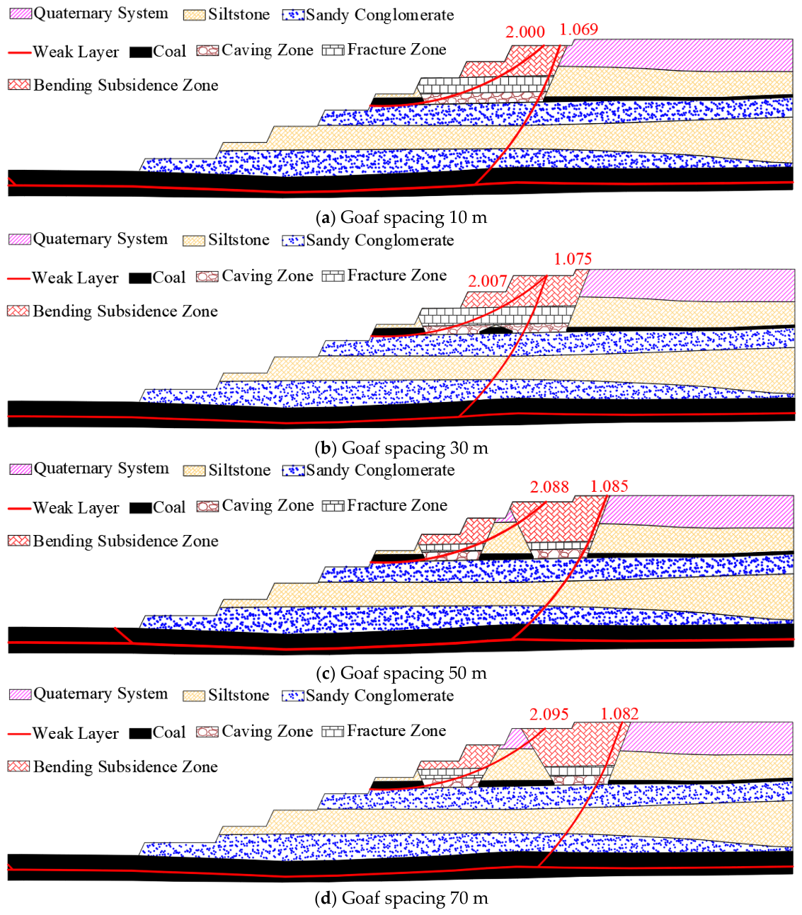
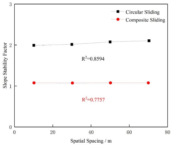
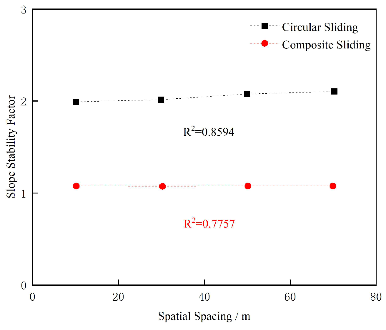
Assuming a goaf span of 50 m, with all selected sliding surfaces passing through the three zones, four groups of goaf spacing distances (10 m, 30 m, 50 m, and 70 m) were analyzed to evaluate their impact on slope stability. When circular sliding occurs, the slope stability factors are 2.000, 2.007, 2.088, and 2.095, respectively. For composite sliding scenarios, the corresponding stability factors are 1.069, 1.075, 1.085, and 1.082, respectively. For the four inter-goaf-spacing cases, the factor of safety for composite sliding is approximately 46.4–48.4% lower than that for circular sliding. Thus, based on the deterministic factor-of-safety comparison, composite sliding represents the more critical potential failure mode under all investigated spacing conditions. As the goaf spacing increases, the proportion of non-collapsed deformation area within the composite sliding mass increases, resulting in a corresponding enhancement of the slope stability factor. In cases where overlapping caving deformation zones exist, the circular sliding surface passes only through the “three zones” within the caving deformation area, leading to minimal variations in the slope stability factor. When the goaf spacing increases to the extent that no overlapping zones exist in the caving deformation areas of the double goafs, the circular sliding surface traverses through the intact rock mass, consequently increasing the slope stability factor. It should be noted that the four discrete spacing cases considered here are intended to characterize the general influence of inter-goaf spacing rather than to identify a statistically defined critical spacing. The calculation results are shown in Figure 14. The influence of goaf spacing on slope stability is illustrated in Figure 15.
Figure 14.
Diagram of calculation results.
Figure 15.
Variation curve of goaf spacing and slope stability.
5.4. Discussion, Model Limitations, and Applicability
The present study focuses on the mechanical influence of historical underground goafs on overburden deformation and open-pit slope stability. Accordingly, the 3DEC simulations and limit-equilibrium analyses were conducted without explicitly considering groundwater flow, pore-water pressure, rainfall infiltration, or seasonal variations in rock moisture. The results therefore represent the mechanical response of the slope under the prescribed material properties and self-weight-dominated stress conditions.
Hydrological processes may further modify the stability of a goaf-affected slope. Mining-induced fractures can increase the hydraulic connectivity of the overburden and provide preferential pathways for infiltration. An increase in pore-water pressure along fractures or weak interlayers may reduce effective normal stress and consequently decrease the available shear resistance. In addition, moisture-induced degradation of mudstone, weak interlayers, or fractured rock masses may further reduce cohesion and stiffness [26]. These effects could amplify the mechanical deterioration associated with underground goafs and may lead to lower factors of safety than those obtained from the present purely mechanical analysis.
Seasonal changes in rainfall and groundwater conditions may also alter the spatial distribution of pore pressure and rock-mass strength. Therefore, the calculated factors of safety in this study should not be interpreted as representing extreme wet-season or transient infiltration conditions. Instead, the results are intended to quantify the relative effects of goaf width, goaf location, and inter-goaf spacing under a consistent mechanical framework.
Future studies should further establish a hydro-mechanical coupling framework by incorporating groundwater level variation, fracture permeability evolution, pore-water pressure distribution, and rainfall infiltration processes. The coupled model should consider the interaction between mining-induced structural damage and hydraulic weakening of rock masses and weak interlayers, thereby improving the prediction capability of slope instability under realistic mining and climatic conditions.
The overburden-deformation results and slope-stability calculations together indicate that the influence of underground goafs is transmitted to the slope through the spatial evolution of mining-induced damage zones. Changes in goaf width and inter-goaf spacing modify the extent and overlap of the caving, fractured, and bending-subsidence zones. When these weakened zones intersect a potential sliding mass, the proportion of rock with reduced mechanical properties increases, thereby decreasing the available shear resistance along the potential failure path. Conversely, when the goaf is located farther from the slope or when the overlap between adjacent-goaf deformation fields decreases, a larger proportion of the potential sliding mass remains in the intact-rock state, resulting in a higher factor of safety. Thus, the overburden movement characteristics obtained from the 3DEC simulations provide the physical basis for the variations in slope stability identified by the limit-equilibrium analyses.
The approximately linear decrease in the factor of safety with increasing goaf width should be interpreted in the context of the deterministic parametric design adopted in this study. Only one geometric variable was changed in each analysis, while the slope geometry, mechanical parameters, and other boundary conditions were maintained constant. Consequently, increasing goaf width progressively increases the extent of mining-affected rock involved in the potential sliding mass without introducing simultaneous variations in other controlling factors. Within the relatively narrow goaf-width range of 20–50 m, this produces a smooth response that can be approximated by a linear relationship. The R2 values of 0.9564 and 0.9712 therefore describe the goodness of fit for the four investigated deterministic cases rather than demonstrating a universal linear relationship. Extrapolation of these regressions beyond the investigated range is not recommended because more complex nonlinear responses may occur when goaf geometry, failure-surface configuration, material properties, groundwater conditions, or their interactions change substantially.
A quantitative comparison of the two candidate failure modes was further conducted for all parametric cases considered in this study. The relative reduction in factor of safety for composite sliding compared with circular sliding was calculated as ΔF = (Fcircular − Fcomposite)/Fcircular × 100%. For the goaf-width cases, the reduction ranges from approximately 53.9% to 55.2%. For the goaf-location cases, it ranges from approximately 46.5% to 60.3%, while for the inter-goaf-spacing cases it ranges from approximately 46.4% to 48.4%. Composite sliding therefore yields a lower factor of safety in all 13 deterministic cases investigated, with an overall reduction of approximately 46.4–60.3% relative to circular sliding. This consistent difference provides quantitative support for identifying the weak-interlayer-controlled composite mode as the more critical potential failure mode for the investigated slope.
It should be emphasized that the term “more critical” refers to the deterministic comparison of factors of safety and should not be interpreted as the probability of occurrence of a particular failure mode. A rigorous probabilistic analysis would require statistical distributions and spatial-variability information for parameters such as cohesion, friction angle, unit weight, weak-interlayer properties, and goaf geometry, which are not available in the present dataset. Similarly, an energy-based comparison would require an additional failure-assessment framework and numerical outputs beyond the present limit-equilibrium analysis. Therefore, unsupported probability distributions or energy criteria were not introduced in the present study. Probabilistic and energy-based analyses are considered important directions for future research.
Several additional limitations of the present study should be acknowledged. First, the numerical and limit-equilibrium analyses were developed for a single open-pit coal mine and were based on a deterministic set of geological and mechanical parameters. Spatial variability and statistical uncertainty in rock-mass strength, discontinuity properties, weak-interlayer parameters, and goaf geometry were not explicitly considered. Second, although the geometry of the historical goafs was constrained by geophysical investigations and the numerical results were compared with empirical estimates, direct field measurements of the internal boundaries of the caving and fractured zones were unavailable. Third, only discrete values of goaf width, location, and inter-goaf spacing were investigated. Consequently, the quantitative relationships and transition ranges identified in this study, including the approximately 50 m inter-goaf spacing observed in some cases, should be regarded as site-specific rather than universally applicable. In addition, the use of the Mohr–Coulomb constitutive model represents a simplification of the post-failure behavior of the rock mass because strain-dependent degradation from peak to residual strength is not explicitly represented. Therefore, the present model is intended primarily to characterize the overall spatial pattern and relative variation in mining-induced deformation rather than the complete progressive post-peak failure process. Future work should incorporate strain-softening behavior when sufficient laboratory or field data become available for reliable calibration of post-peak strength evolution. A further limitation is the absence of direct calibration using field-monitored displacement data or borehole observations of fracture-zone boundaries. Therefore, the absolute accuracy of the predicted displacement magnitude and deformation-zone extent cannot be fully quantified. The numerical results should be interpreted primarily as comparative trends illustrating the influence of different goaf configurations on overburden deformation and slope stability rather than as exact predictions of field-scale failure evolution.
A further numerical limitation concerns computational-domain and block-size sensitivity. A formal domain-size sensitivity analysis was not conducted; therefore, although the model boundaries were positioned outside the principal region of interest, some residual influence of boundary location cannot be completely excluded. Similarly, a systematic block-size convergence analysis was not performed. The same block-discretization strategy was applied consistently throughout the parametric simulations, and the present results are therefore interpreted primarily in terms of relative trends among the investigated cases rather than strictly mesh-independent absolute predictions. Future work should systematically vary both the computational-domain dimensions and block resolution to quantify boundary sensitivity and numerical convergence.
Despite these limitations, the proposed framework is transferable to other open-pit mines affected by historical underground workings. The general procedure of constraining goaf geometry using field investigation, characterizing mining-induced overburden deformation using 3DEC, assigning spatially differentiated mechanical properties to the resulting deformation zones, and evaluating competing slope failure modes using limit-equilibrium analysis can be applied to other geological settings. However, quantitative application to another mine requires site-specific recalibration of stratigraphy, mining depth and height, goaf geometry, rock-mass and discontinuity properties, weak-interlayer characteristics, and hydrogeological conditions. Future studies should therefore combine direct field monitoring, coupled hydro-mechanical modeling, probabilistic or uncertainty analysis, and applications to open-pit mines with different geological structures to further evaluate the robustness and general applicability of the proposed methodology.
6. Conclusions
(1) Underground extraction produces progressive deformation and failure of the overburden, and the resulting deformation structure depends strongly on the goaf geometry. Under partial-extraction conditions, the overburden is mainly characterized by caving and fractured zones. As the extraction extent increases, the mining-induced deformation field expands upward and laterally. In the 50 m wide single-goaf case, a distinct bending-subsidence zone develops above the fractured zone, forming a complete caving–fractured–bending-subsidence zonation. For the 50 m wide single-goaf case, the simulated caving- and fractured-zone heights are 3.8 m and 13.0 m, respectively.
(2) Adjacent goafs modify the overburden deformation pattern through interaction and overlap of their mining-induced displacement fields. At relatively small inter-goaf spacings, deformation zones generated by the two goafs overlap, which generally enhances roof deformation and may increase the development extent of the caving or fractured zones. For the 30 m wide double-goaf case, a local separation zone develops above the caving zone and is identified as a pseudo-fractured zone. As inter-goaf spacing increases, the overlap of the deformation fields generally decreases and the interaction between adjacent goafs weakens.
(3) The influence of inter-goaf spacing is not characterized by a single universal threshold. Although the interaction between adjacent goafs generally weakens with increasing spacing, the response depends on both goaf width and the deformation parameter considered. The value of approximately 50 m observed in several simulations should therefore be interpreted as a site-specific transition range rather than a universal critical spacing. Additional simulations with finer spacing increments and uncertainty analysis would be required to define a statistically robust critical distance.
(4) The slope-stability results demonstrate that the influence of underground goafs is controlled by the extent to which mining-induced deformation zones intersect the potential sliding mass. Increasing goaf width generally enlarges the proportion of mining-affected rock within the sliding mass and reduces the available shear resistance, whereas increasing the horizontal distance between the goaf and the slope allows a larger proportion of the sliding mass to remain in the intact-rock state. Accordingly, within the investigated goaf-width range of 20–50 m, the factors of safety for both circular and composite sliding exhibit an approximately linear decreasing trend with increasing goaf width, while the factor of safety increases as the goaf is located farther from the slope face. Two potential failure modes were evaluated: circular sliding and composite sliding controlled by the weak interlayer of the No. 1 coal seam. In all 13 deterministic cases investigated, composite sliding yields a lower factor of safety than circular sliding, with an overall relative reduction of approximately 46.4–60.3%, indicating that the weak-interlayer-controlled composite mode is the more critical potential failure mode under the investigated conditions. This conclusion represents a deterministic comparison based on calculated factors of safety under the prescribed geological and mechanical conditions, rather than a probabilistic prediction of failure occurrence.
(5) The proposed 3DEC–limit-equilibrium framework provides a transferable approach for evaluating open-pit slopes affected by historical underground workings; however, the quantitative results obtained in this study are site-specific. Application to other mines requires recalibration using local stratigraphy, goaf geometry, mining conditions, rock-mass and discontinuity properties, weak-interlayer characteristics, and hydrogeological conditions. The present analysis is also limited by the use of deterministic parameters, the absence of direct field measurements of the internal overburden deformation-zone boundaries, and the exclusion of hydro-mechanical coupling. In addition, the effects of computational-domain size, block discretization, and parameter uncertainty on the absolute numerical results require further systematic investigation. Future work should incorporate field monitoring, probabilistic uncertainty analysis, coupled hydro-mechanical modeling, and validation at mines with different geological conditions to further assess the general applicability of the proposed methodology.
From an engineering and mine-management perspective, the results indicate that historical underground goafs should be explicitly incorporated into open-pit slope hazard zoning and mine-planning decisions rather than treated simply as isolated subsurface voids. Before pit-wall advance toward areas containing undocumented or poorly constrained workings, geophysical investigation should be combined with numerical evaluation of the mining-induced deformation zones and their potential intersection with critical sliding surfaces. Slope sectors in which caving or fractured zones intersect weak-interlayer-controlled potential sliding paths should receive priority for monitoring and, where necessary, reinforcement or mining-sequence adjustment. Importantly, site-specific transition distances identified from numerical simulations, such as the approximately 50 m spacing observed in several cases in this study, should not be directly adopted as universal regulatory or design thresholds without recalibration for local geological and mining conditions. The principal practical takeaway of the proposed framework is therefore to support site-specific, goaf-aware slope risk assessment and targeted monitoring before continued open-pit excavation. It should be noted that the comparison between circular and composite sliding represents deterministic mechanical criticality based on calculated safety factors, rather than the probability of occurrence of different failure mechanisms.
Author Contributions
Conceptualization, M.J. and D.W.; methodology, M.J. and D.W.; software, M.J.; validation, M.J., D.W. and Y.T.; formal analysis, M.J.; investigation, M.J. and Y.T.; resources, M.J. and D.W.; data curation, M.J. and Y.T.; writing—original draft preparation, M.J.; writing—review and editing, D.W. and Y.T.; visualization, M.J. and Y.T.; supervision, D.W.; project administration, M.J. and D.W. All authors have read and agreed to the published version of the manuscript.
Funding
Major science and technology ‘list’ project in Ordos City, Inner Mongolia Autonomous Region, China (JBGS-2023-003/24-1004); Inner Mongolia Autonomous Region Science and Technology Plan (No. 2025YFKL0004); Xing Liao Talent Plan (No. XLYC2202004).
Data Availability Statement
The data presented in this study are available from the corresponding author upon reasonable request. The raw engineering geological and goaf investigation data are not publicly available due to the confidentiality requirements of the engineering project.
Conflicts of Interest
The authors declare no conflicts of interest.
References
- Li, H.F. Research on the Development Strategy of China’s Coal Industry. China Coal 2004, 30, 24–25+49. [Google Scholar]
- Zhang, Z.P. Research on initial roof release technology for hydraulic fracturing of hard and difficult to collapse roof slabs. Coal Sci. Technol. 2018, 46, 86–89. [Google Scholar]
- Chai, H.B.; Cao, P.; Chai, G.W.; Lin, H. Influence of mining airspace on slope stability. J. Cent. South Univ. (Nat. Sci. Ed.) 2010, 41, 1528–1534. [Google Scholar]
- Shen, T.; Zhu, Z.R. Analysis of measured parameters of coal mining subsidence in northern Shaanxi mining area. Coal Sci. Technol. 2019, 47, 207–213. [Google Scholar]
- Miao, T.L. Analysis of geological conditions of slopes in Anjialing open pit mine. Open Pit Min. Technol. 2015, 30, 29–31+35. [Google Scholar]
- Chen, X. Research on Surface Movement and Surface Water Prevention and Control Measures of Working Face from 9504 to 9508 in Antaibao Side Gang Mining Area. Master’s Thesis, China University of Geosciences, Beijing, China, 2019. [Google Scholar]
- Feng, H.B. Research on the Stability of Grassland Ecosystem and Its Ecological Geological Mechanism Under the Influence of Coal Mining. Ph.D. Thesis, China University of Geosciences, Wuhan, China, 2021. [Google Scholar]
- Wang, D. Research on Rock Movement Law and Steady State Analysis of Reversed Inclination Slope in Open Well Joint Mining. Ph.D. Thesis, Liaoning Technology University, Fuxin, China, 2011. [Google Scholar]
- Wang, C.Y.; Li, J.P.; Liu, W. Research on the effect of well mining collapse on slope stability. Coal Technol. 2018, 37, 33–35. [Google Scholar]
- Lai, X.Y.; Jiang, L.C. Analysis of the influence of the direction of civil mining airspace on the stability of open pit mine slopes. Min. Res. Dev. 2012, 32, 26–28. [Google Scholar]
- Miao, Y.; Wu, M.; Zhao, T.Y. Influence of mining airspace on open pit mining and countermeasures. Surf. Min. Technol. 2018, 33, 21–25. [Google Scholar]
- Gao, S.; Du, W.; Liu, Y.; Chai, J.; Gao, D.; Ma, C.; Chen, J. Reasonable top coal thickness for large cross-section open-off cut in lower-layer mining. Front. Earth Sci. 2023, 11, 1301595. [Google Scholar] [CrossRef] [Scilit]
- Zhang, Y.; Qian, C.; Wang, X.; Chen, X.; Chang, Z.; Wang, J.; Niu, Z. Study on prevention and control mechanism of runoff water hazard in thick coal seam mining in valley terrain. Front. Earth Sci. 2023, 11, 1140491. [Google Scholar] [CrossRef] [Scilit]
- Yang, S.; Xu, N.; Liu, H.; Zhang, X.; Mei, S. Research and application of ‘three zones’ range within overlying strata in goaf of steep coal seam. Front. Energy Res. 2024, 12, 1333016. [Google Scholar] [CrossRef] [Scilit]
- Chen, M.; Zhang, C.; Canbulat, I.; Saydam, S. A DEM-DFN Method for Assessing Mining-Induced Continuous Fracturing and Fracture Connectivity in Rock Masses. Rock Mech. Rock Eng. 2025, 58, 12207–12230. [Google Scholar]
- Li, Z.; Xu, T.; Zhao, L.; Liu, Y.; Xu, Y.; Heap, M.J.; Utili, S.; Liu, B.; Su, B. Enhancing stability analysis of open-pit slopes via integrated 3D numerical modeling and data monitoring. Eng. Fail. Anal. 2024, 163, 108495. [Google Scholar] [CrossRef] [Scilit]
- Zhang, Q.W.; Hou, K.P. Safe mining depth for undermining and very undermining. Min. Metall. 2004, 13, 1–5. [Google Scholar]
- Guo, T.J.; Gao, C.; Zhao, J.T.; Huang, Z.Y. Transportation law of overburden in inclined coal seams and calculation of the height of “upper three zones”. Coal Technol. 2024, 43, 32–37. [Google Scholar]
- Xia, X.H.; Wei, H.T.; Yang, W.F.; Xu, H.Y.; Zhang, F.Z. Experimental study on mining overburden and surface movement and deformation law under thick loose layer. Sci. Technol. Eng. 2023, 23, 14053–14059. [Google Scholar]
- Tian, S.K.; Guo, T.S.; Wu, D. Development trend of slope engineering in surface coal mine. Surf. Min. Technol. 2014, 29, 6–9. [Google Scholar]
- Guo, Q.B.; Cai, Y.; Lu, X.; Yu, X.; Wu, T. Application of 3DEC numerical simulation technology in the teaching of “deformation and subsidence engineering”. Exp. Technol. Manag. 2023, 40, 194–199. [Google Scholar]
- Gao, J.L.; Chen, S. Numerical simulation of “three zones” delineation of overlying rock layers in the mining air-space. J. Saf. Environ. 2016, 16, 36–39. [Google Scholar]
- Wang, H.; Gao, Y.T.; Jin, A.B.; Zhang, K. Selection of stiffness parameters and three-dimensional discrete element simulation of jointed rock bodies. J. Rock Mech. Eng. 2014, 33, 2894–2900. [Google Scholar]
- Chang, J. Study on foundation stability of buildings above old mining area. J. Xi’an Coll. Min. 1995, 15, 29–33. [Google Scholar]
- Sun, Y.; Zhao, H.Z.; Zhu, W.B.; Qin, B.D. Study on slope stability of thick loess layer in Daliuta open pit mining area. Open Pit Min. Technol. 2023, 38, 91–94. [Google Scholar]
- Song, G. Research on control technology of surrounding rock in alkaline-rich water weakly cemented soft rock road-way. Coal Eng. 2023, 55, 58–62. [Google Scholar]

Disclaimer/Publisher’s Note: The statements, opinions and data contained in all publications are solely those of the individual author(s) and contributor(s) and not of MDPI and/or the editor(s). MDPI and/or the editor(s) disclaim responsibility for any injury to people or property resulting from any ideas, methods, instructions or products referred to in the content. |
© 2026 by the authors. Licensee MDPI, Basel, Switzerland. This article is an open access article distributed under the terms and conditions of the Creative Commons Attribution (CC BY) license.