


Abstract
Lined rock caverns offer a promising option for underground hydrogen, helping to mitigate renewable intermittency and enhance system stability. Considering the geological characteristics of hard rock formations in Southern Ontario, Canada, this study establishes a thermo–gas–mechanical coupled framework that incorporates hydrogen mass and energy evolution in the cavern, gas–wall convective heat exchange, dynamic cavern-volume feedback, and the deformation behaviour of the sealing layer, concrete lining, and surrounding rock. The influences of cavern geometry, sealing material, and in situ stress on the short–term thermodynamic and mechanical responses are further examined. The results show that hydrogen temperature and pressure exhibit clear stage–dependent evolution during the charging–storage–discharging cycle. The comparison between the first and 20th operating cycles indicates that repeated operation mainly causes a moderate adjustment of the cyclic thermal state and temperature–pressure baseline, without changing the overall stage–dependent response pattern. During charging, temperature and pressure increase simultaneously; during storage, both gradually decrease as thermal energy is transferred to the cavern wall; and during discharging, expansion causes pronounced cooling and depressurization, followed by gradual recovery driven by heat transfer from the surrounding rock. Cavern geometry significantly affects stress redistribution around the cavern. The circular cavern shows a relatively uniform stress distribution, whereas the arched cavern is more prone to local stress concentration near the sidewall–floor transition zone. The sealing material mainly influences gas temperature fluctuations through its thermal conductivity. The fibre–reinforced plastic (FRP) sealing layer amplifies thermal fluctuations during cyclic operation, whereas the steel sealing layer promotes heat dissipation through the lining and surrounding rock, thereby moderating cavern–gas temperature variations. In situ stress difference further controls the directional distribution of stresses around the cavern. As the minimum horizontal principal stress increases, compressive stress concentration at the crown and invert becomes stronger, while relative stress release occurs near the sidewalls. These findings provide a thermo–mechanical basis for preliminary cavern–geometry design, comparison of sealing–layer thermal performance, and assessment of in situ stress adaptability for lined rock cavern hydrogen storage in Southern Ontario.
1. Introduction
Although worldwide energy demand continues to rise, fossil fuels still dominate the global energy structure. Global CO2 emissions from coal, oil, and natural gas in 2025 increased by approximately 1.0%, 1.1%, and 1.3%, respectively, compared with those in 2024 [1]. Heavy reliance on fossil fuels has generated substantial greenhouse gas emissions and raised serious environmental concerns [2,3]. Renewable energy is essential for achieving carbon neutrality and alleviating global warming. However, solar and wind power are highly weather–dependent and sensitive to climatic variability, resulting in pronounced intermittency and supply fluctuations [4]. As a clean energy carrier, hydrogen can store surplus renewable electricity and later support power generation, industrial production, and other applications [5], thereby helping balance renewable supply and demand. Nevertheless, the large–scale deployment of renewable hydrogen depends not only on the cost of hydrogen production but also on storage capacity, operational flexibility, and safety [6,7,8]. At present, green hydrogen storage technologies are rapidly developing worldwide. For example, the Advanced Clean Energy Storage project in Utah, USA, plans to use two local salt caverns for green hydrogen storage, with an estimated combined capacity of approximately 300 GWh [9]. This project demonstrates the engineering potential of underground storage for renewable peak shaving and broader hydrogen deployment.
Hydrogen may be contained either in high–pressure vessels [10] or within suitable geological formations. For large–scale, long–duration applications, underground hydrogen storage is regarded as a promising option, with principal forms including salt caverns, aquifers, depleted hydrocarbon reservoirs, and lined rock caverns [11]. The rock–salt formations hosting salt caverns are characterized by low permeability and strong sealing capacity, while salt caverns generally provide rapid cycling performance, but their storage capacity and long–term stability are limited by cavern size, salt–layer integrity, and internal temperature–pressure conditions [12,13,14]. Depleted hydrocarbon reservoirs and saline aquifers provide substantial storage capacity and opportunities for reusing existing infrastructure; however, interactions between hydrogen and reservoir fluids, minerals, and microorganisms may lead to gas loss, compositional changes, and reduced withdrawal gas purity [11,15]. In comparison, lined rock caverns consist of a lining system that provides gas–tightness and a surrounding rock mass that bears the internal pressure [16]. They can be excavated in rock masses with sufficient strength and integrity, are less dependent on salt formations or high–porosity and high–permeability reservoirs, and therefore offer greater site flexibility. Their geometry and structural configuration can also be designed according to the required storage capacity and operating pressure [17,18]. The HYBRIT project in Sweden has constructed a lined rock cavern test facility for cyclic high–pressure hydrogen storage, aiming to develop a 100 m3 hard–rock cavern for hydrogen storage and promoting the transition of lined rock cavern technology from natural gas storage experience toward hydrogen storage demonstration [19,20]. In Canada, the geological suitability for underground hydrogen storage varies according to regional geological conditions and storage type. National–scale assessments have identified storage potential in the sedimentary basins of Western and Atlantic Canada, the Southern Ontario sedimentary basin, and the crystalline rocks of the Canadian Shield. The sedimentary basins contain salt formations, depleted hydrocarbon reservoirs, and deep saline aquifers that may support different forms of large–scale geological storage. In comparison, opportunities for excavated rock–cavern storage are mainly associated with the competent crystalline rocks of the Canadian Shield and low–permeability sedimentary rocks in Southern Ontario [21]. Southern Ontario is particularly relevant because several potential storage settings occur within the same sedimentary basin, including Silurian bedded salts, depleted Ordovician natural–gas reservoirs, saline aquifers in Cambrian sandstone, and excavated caverns in Ordovician argillaceous limestone [21,22]. Among these settings, the lower Cobourg Formation near Kincardine provides a well–characterized host–rock setting for LRC assessment because of its low permeability, relatively high strength, limited fracture development, substantial stratigraphic confinement, and documented regional stress conditions. These characteristics make Southern Ontario a representative geological setting for investigating LRC hydrogen storage in low–permeability sedimentary rock [23], while LRCs may serve as a flexible complement to salt–cavern, depleted–reservoir, and saline–aquifer storage rather than a universally superior storage option.
At present, studies on underground hydrogen storage in lined rock caverns mainly rely on engineering demonstrations, field monitoring, and numerical simulations. Because cyclic high–pressure hydrogen tests require strict gas–tightness, safety control, and long–term monitoring, publicly available field data remain limited. Existing experimental evidence remains largely based on hydrogen–storage demonstrations, such as HYBRIT and analogous compressed–air tests in lined rock caverns, where gas thermodynamic evolution and lining–host–rock deformation were monitored to assess feasibility under pressurized operation [18,24,25]. Accordingly, numerical simulation provides an effective means to evaluate thermodynamic behaviour and structural safety in lined rock caverns used for hydrogen storage. Existing studies have commonly employed finite–element, finite-difference, and discrete-fracture-network methods to develop coupled models involving gas thermodynamics, solid heat transfer, structural mechanics, and leakage or diffusion processes. Such models have been applied to assess gas temperature–pressure evolution during cyclic operation, gas–wall thermal exchange, deformation of the sealing–lining system, host–rock stress redistribution, and potential failure risks. Thermophysical models typically couple mass and energy balances with real–gas equations of state to predict pressure–temperature evolution during underground hydrogen storage and characterize thermal exchange with the surrounding media [26]. Thermo–mechanical models further couple gas thermodynamics with the thermal and deformation behaviour of the lining–host–rock system. For example, Hu et al. [27] examined how steel and FRP sealing–layer type and thickness affect temperature and stress fields, whereas another study by Hu et al. [28] evaluated lined rock cavern storage under hydrogen and compressed–air operation from thermodynamic and mechanical perspectives. From the perspective of cavern design, recent numerical studies have also investigated the influence of cavern geometry, although mainly for solution–mined salt caverns. Speirs et al. [29] employed a three–dimensional finite–element model and emphasized the importance of realistically representing cavern geometry under cyclic hydrogen–storage loading, whereas Harati and Rezaei Gomari [30] used three–dimensional finite–difference simulations to demonstrate that cavern shape and aspect ratio strongly affect stress redistribution, deformation, and long–term volume convergence. For complex rock masses, Zhao et al. [31] employed a discrete-fracture-network method to evaluate fracture–controlled damage in the surrounding rock and concrete lining under high internal gas pressure. In addition, uncertainty analysis and reliability–based design have recently been introduced into the assessment of lined rock caverns. Damasceno et al. [19] integrated adaptive directional importance sampling and 3D finite-element modelling to assess lined rock cavern design reliability and quantify potential impacts from corrosion and hydrogen embrittlement via sensitivity analysis.
Overall, existing simulations of hydrogen storage in lined rock caverns have mainly focused on temperature–pressure prediction, sealing material performance, fractured rock mass deformation, or structural reliability as individual or localized issues. Although recent numerical studies have demonstrated the important influence of cavern geometry in salt–cavern hydrogen storage, the corresponding geometric effects in engineered LRC systems and their interactions with the sealing–lining structure and surrounding rock remain insufficiently understood. The coupled effects of engineering design parameters and geological conditions remain insufficiently explored. Moreover, most existing lined rock cavern projects and models are based on igneous or metamorphic hard rock formations, whereas the thermo–mechanical response of hydrogen storage caverns in layered sedimentary rocks such as the argillaceous limestone in Southern Ontario remains relatively unclear. Therefore, a unified thermo–gas–mechanical framework is needed to clarify how cavern geometry, sealing material, and in situ stress jointly govern the safety of lined rock cavern hydrogen storage.
Based on the above considerations, this study uses the low–permeability sedimentary formations in Southern Ontario, Canada, as the geological background and develops a thermo–gas–mechanical coupling model in COMSOL Multiphysics 6.2. The model incorporates gas mass and energy conservation, gas–wall convective heat exchange, thermoelastic deformation of the lining–host–rock system, and dynamic cavern–volume feedback. Its accuracy is verified by comparing the predicted gas temperature–pressure evolution with existing numerical results. Under a unified 20–cycle charging–discharging operation scheme, the effects of cavern geometry and sealing material on the thermodynamic and mechanical responses of the storage system are analyzed. Furthermore, stress redistribution at the cavern crown, invert, and sidewalls is analyzed under varying in situ stress differences to reveal how cavern geometry, sealing material, and regional stress conditions govern the safety of lined rock cavern hydrogen storage. The results provide a theoretical basis for preliminary cavern–shape assessment, comparison of sealing–material thermal performance, and in situ stress adaptability evaluation for lined rock cavern hydrogen storage in Southern Ontario.
2. Geological Background and Model Construction
2.1. Regional Geological Background
Canada contains several geological settings with potential for underground hydrogen storage, but their suitability varies according to host–rock characteristics and storage concept. To place the selected geological setting in a broader national context, Table 1 compares the representative geological conditions, potential storage options, and relevance to rock–cavern storage across major Canadian regions. As summarized in Table 1, the Western Canadian and Atlantic sedimentary basins are primarily characterized by salt formations and porous geological storage options, whereas the principal regions identified for excavated rock–cavern assessment are the Canadian Shield and the Southern Ontario sedimentary basin. Southern Ontario is particularly relevant to the present study because it combines several potential storage formations with a well–characterized low–permeability sedimentary host rock for LRC development.
Table 1.
Comparison of representative geological regions for underground hydrogen storage in Canada.
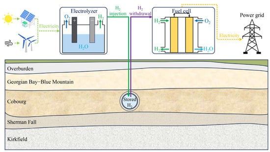
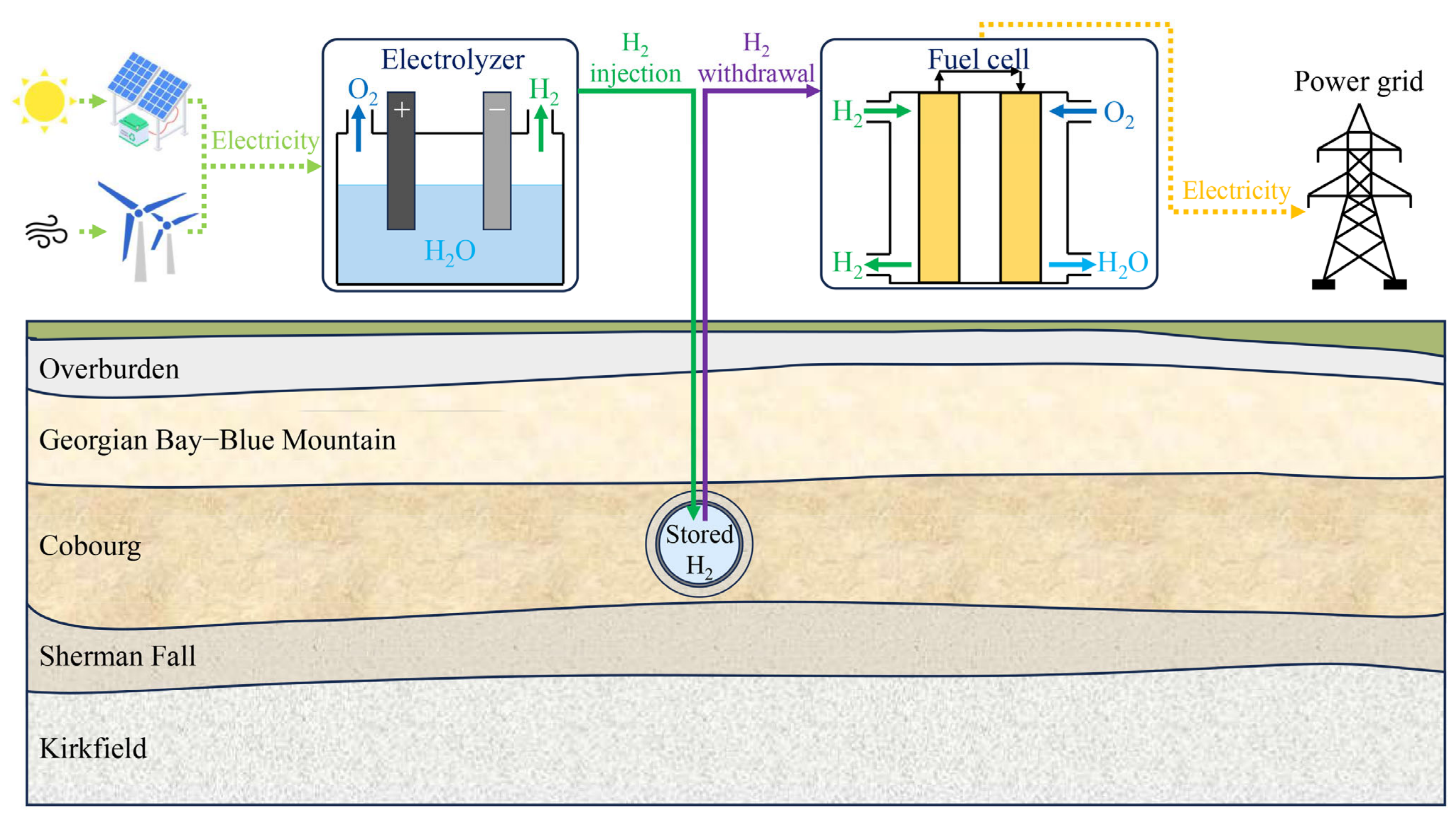
The specific geological setting considered in this study is located near Kincardine in the Bruce region of Southern Ontario, Canada, along the eastern margin of the Michigan Basin [32]. Nearly horizontal Paleozoic sedimentary strata are developed beneath the ground surface in this area and mainly consist of mudstone, shale, limestone, dolostone, and local sandstone. Based on deep borehole cores and geophysical logging data, the Middle Ordovician Cobourg Formation consists of the upper Collingwood Member and the lower argillaceous limestone member. In the DGR–2 borehole, the top and bottom depths of the lower Cobourg Formation are approximately 659.5 m and 688.1 m, respectively, with a thickness of about 28.6 m. It is overlain by the Collingwood Member and the low–permeability Blue Mountain and Georgian Bay shales and underlain by the argillaceous limestone of the Sherman Fall Formation. The lower Cobourg Formation is mainly composed of light grey to dark brownish–grey, massive, dense, fine–crystalline to microcrystalline argillaceous limestone. The rock mass is generally intact and has a low degree of fracture development; therefore, it is selected as the representative surrounding rock for the lined rock cavern hydrogen storage model and provides the geological setting for the underground hydrogen storage component of the renewable electricity, electrolysis, storage, and fuel cell power generation system in Southern Ontario (Figure 1).
Figure 1.
Conceptual schematic of lined rock cavern hydrogen storage integrated with the stratigraphic setting in Southern Ontario, Canada [32,33].
Regional tests on the argillaceous limestone of the Cobourg Formation indicate that its uniaxial compressive strength ranges from 22 to 140 MPa, with an average value of 72 MPa; its elastic modulus ranges from 10 to 67 GPa, with an average value of 31.5 GPa. Poisson’s ratio is approximately 0.30, and the density is about 2700 kg/m3 [32]. According to regional in situ stress statistics for Southern Ontario, at a depth of approximately 680 m, the vertical stress is about 18 MPa, while the maximum and minimum horizontal principal stresses are approximately 38 MPa and 18 MPa, respectively. The orientation of the maximum horizontal principal stress is generally N74° E, corresponding to an east–northeast direction. These geomechanical characteristics indicate that the argillaceous limestone of the Cobourg Formation has relatively high strength, a low degree of fracture development, and a well–constrained regional stress background, providing a reasonable geological basis for thermo–gas–mechanical coupling simulations of hydrogen storage in lined rock caverns.
2.2. Mathematical Model
The surrounding rock is represented as a homogeneous equivalent continuum. Natural discontinuities, explicit joint networks, excavation–induced fractures, and discontinuity–controlled leakage pathways are not explicitly included in the present model. In addition, within the simulated 20–cycle operating period, the thermophysical and mechanical properties of the sealing layer, concrete lining, and surrounding rock are assumed to remain unchanged; material degradation associated with hydrogen–induced embrittlement, corrosion, material ageing, and fatigue–damage accumulation is not explicitly considered. These assumptions allow the study to focus on the thermo–gas–mechanical response governed by cavern geometry, sealing material, and regional in situ stress.
2.2.1. Deformation Governing Equation
The sealing layer, concrete lining, and surrounding rock of the lined rock cavern are assumed to behave as linear-elastic materials. Incorporating thermal expansion, the linear-elastic constitutive relation is written as [28]:
where σij is the stress tensor; εij is the strain tensor; G and K are the shear modulus and bulk modulus of the cavern surrounding materials and rock mass, respectively, MPa; v is the Poisson’s ratio of the cavern surrounding materials and rock mass; εkk is the first invariant of the strain tensor; δij is the Kronecker delta; αT is the thermal expansion coefficient of the cavern surrounding materials and rock mass, 1/K; and ΔTc is the temperature change of the cavern surrounding materials and rock mass, K.
The strain–displacement relationship can be expressed as:
where ui,j and ui,j are the partial derivatives of the displacement components ui and uj with respect to the spatial coordinates, respectively.
The stress equilibrium equation can be written as [34]:
where σij,j denotes the divergence of the stress tensor, and fi is the body force in the i–direction.
Combining Equations (1)–(3) yields the governing equation for deformation:
2.2.2. Gas Mass and Energy Conservation Equations
The mass–balance equation accounts for controlled hydrogen injection and withdrawal but does not include an additional leakage term. The sealing layer and cavern boundary are assumed to remain gas–tight during the simulated short–term operating cycle. The cavern gas is treated as a spatially uniform lumped system; therefore, gas temperature, pressure, density, and related properties are defined as time–dependent global variables.
Hydrogen inventory during charging and discharging is governed by the mass balance equation:
where mg is the gas mass in the lined rock cavern, mg = ρgVc, kg; ρg is the gas density, kg/m3; Vc is the cavern volume, m3; t is time, s; and Ci and Co are the mass flow rates of gas inflow and outflow, respectively, kg/s.
Considering the variations in gas density and cavern volume, Equation (5) can be further expanded as:
Accounting for inlet–outlet enthalpy transport, gas–wall thermal exchange, and volume–change work, the gas–phase energy balance is expressed as [35]:
where ug is the specific internal energy of hydrogen in the cavern, J/kg; hi and hg are the specific enthalpies of the injected gas and discharged gas, respectively, J/kg; Qe is the heat transfer rate between the gas and cavern wall, W; and pg is the gas pressure in the cavern, MPa.
Combining energy and mass balance equations, Equation (7) can be reformulated as:
where cv is the constant–volume specific heat capacity of the gas, cv ≈ cv0, J/(kg·K); cv0 is the constant–volume specific heat capacity of the gas at the initial state, J/(kg·K); and Tg is the gas temperature in the cavern, K.
The equation of state for the gas in the cavern can be written as:
where Zg is the gas compressibility factor, defined as Zg = 1 − 9pgTc(6Tc2/Tg2 − 1)/(128pcTg); Tc and pc are the critical temperature and critical pressure of hydrogen, respectively, K and MPa; and R is the specific gas constant of hydrogen, J/(kg·K).
The thermodynamic properties of the gas can be expressed as [36]:
where cp0 is the constant–pressure specific heat capacity of the gas at the initial state, J/(kg·K), and Ti is the injection gas temperature, K.
Thus, Equation (7) can finally be written as:
where ∂ug/∂ρg ≈ −RT02ZT0/ρ0; T0 is the initial gas temperature, K; and ZT0 is the temperature derivative of the gas compressibility factor evaluated at the initial state.
Convective gas–wall heat exchange in the lined cavern is quantified as [37]:
where hc is the average heat transfer coefficient, W/(m2·K); Ac is the heat transfer area between the gas and cavern wall, m2; and Te is the cavern wall surface temperature, K.
2.2.3. Temperature Field Equation
The heat conduction process in the sealing layer, concrete lining, and surrounding rock of the lined rock cavern can be expressed as:
where ρs is the density of the solid material, kg/m3; Cs is the specific heat capacity of the solid material, J/(kg·K); Ts is the solid temperature, K; and ks is the thermal conductivity of the solid material, W/(m·K).
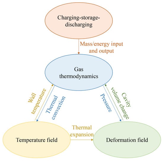
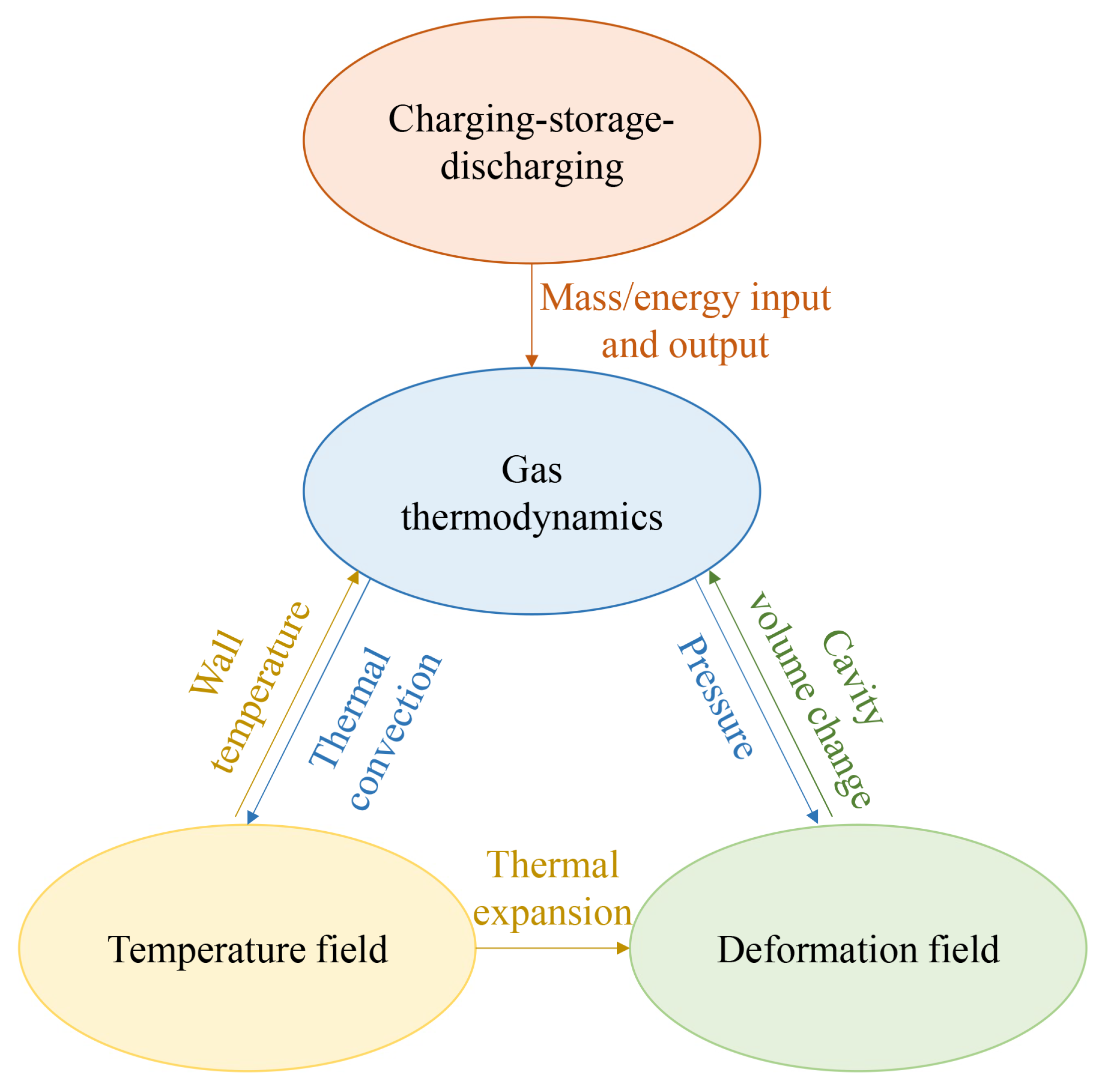
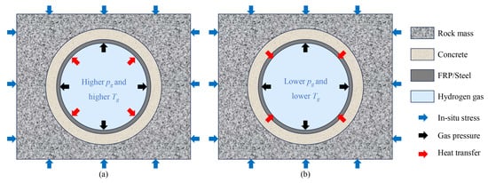
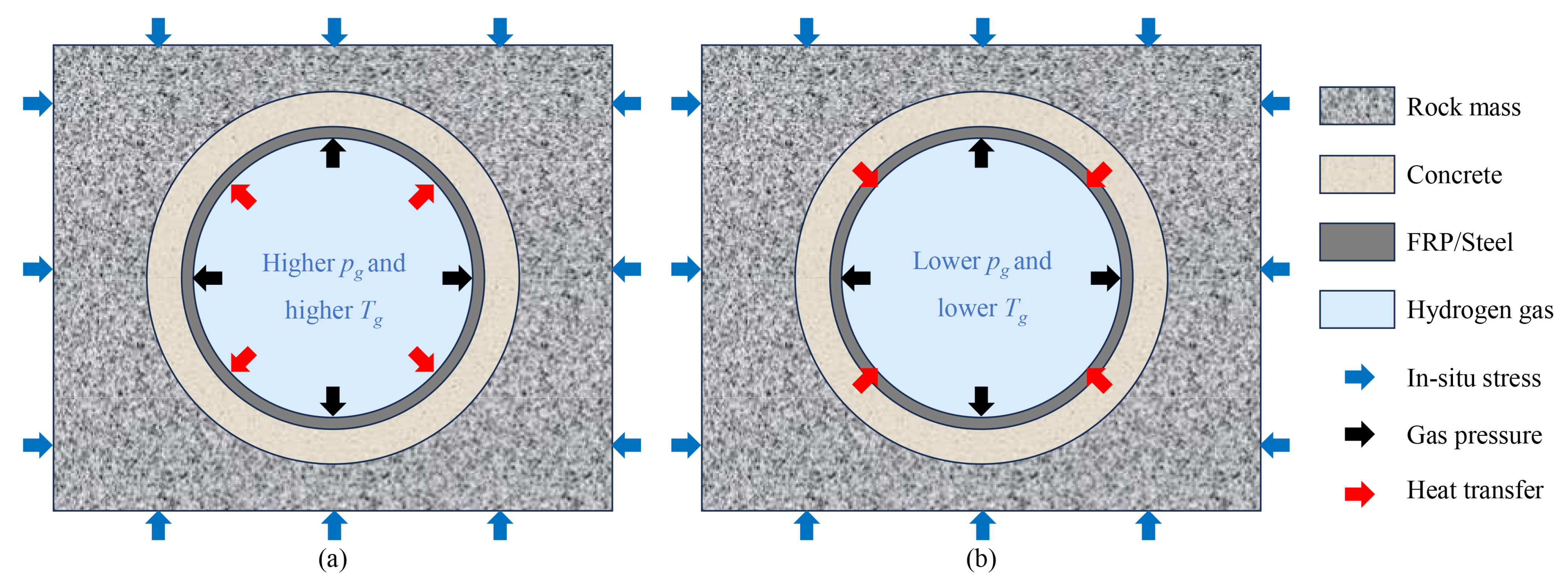
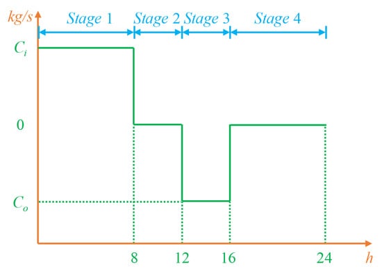
Figure 2 illustrates the thermo–gas–mechanical coupling model for hydrogen storage in a lined rock cavern. The charging and discharging processes (Figure 3) act as operational processes that alter the gas thermodynamics through mass exchange, while the gas thermodynamic response is jointly regulated by cavern volume variation and wall temperature. The time–dependent gas pressure is uniformly applied as a normal load on the inner surface of the sealing layer and is subsequently transferred to the concrete lining. and surrounding rock. Meanwhile, convective heat exchange between the global gas temperature and the local wall temperature is imposed along the same surface. Temperature evolution further modifies deformation and stress redistribution in the lining–host–rock system through thermal expansion, while deformation–induced cavern–volume changes feed back into gas thermodynamics. Together, these interactions establish the thermo–gas–mechanical coupling system governing hydrogen cavern operations.
Figure 2.
Thermo–gas–mechanical coupling framework for lined rock cavern hydrogen storage.
Figure 3.
Schematic diagrams of the gas charging and discharging processes. (a) Gas charging process; (b) gas discharging process.
2.3. Geometric Model Construction
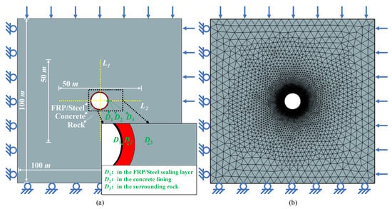
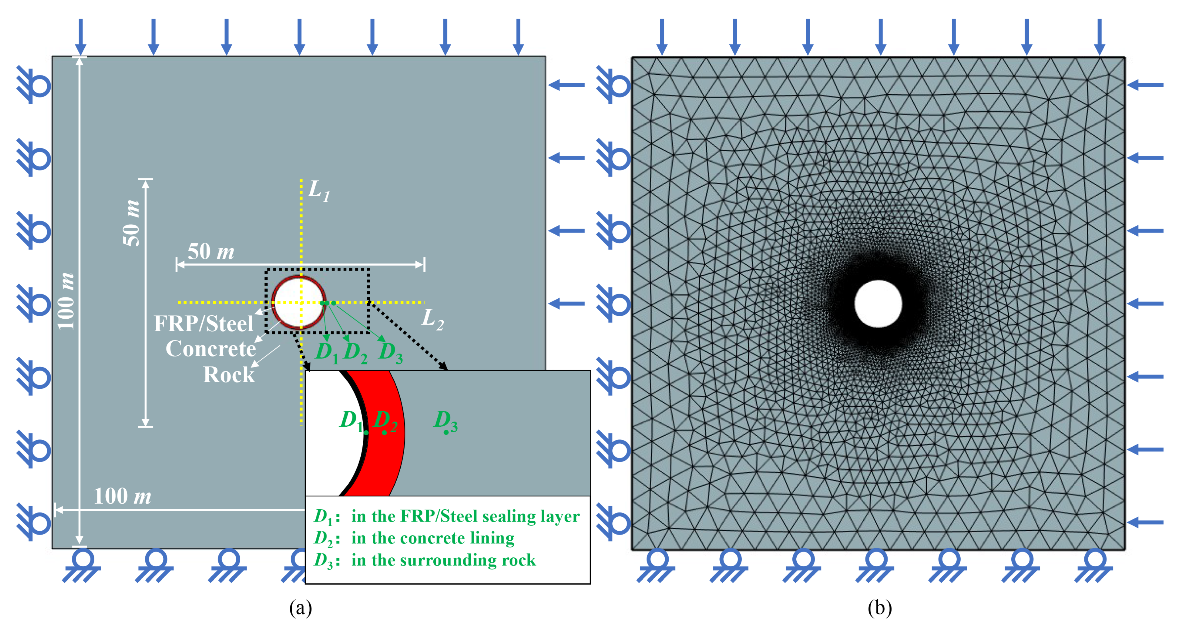
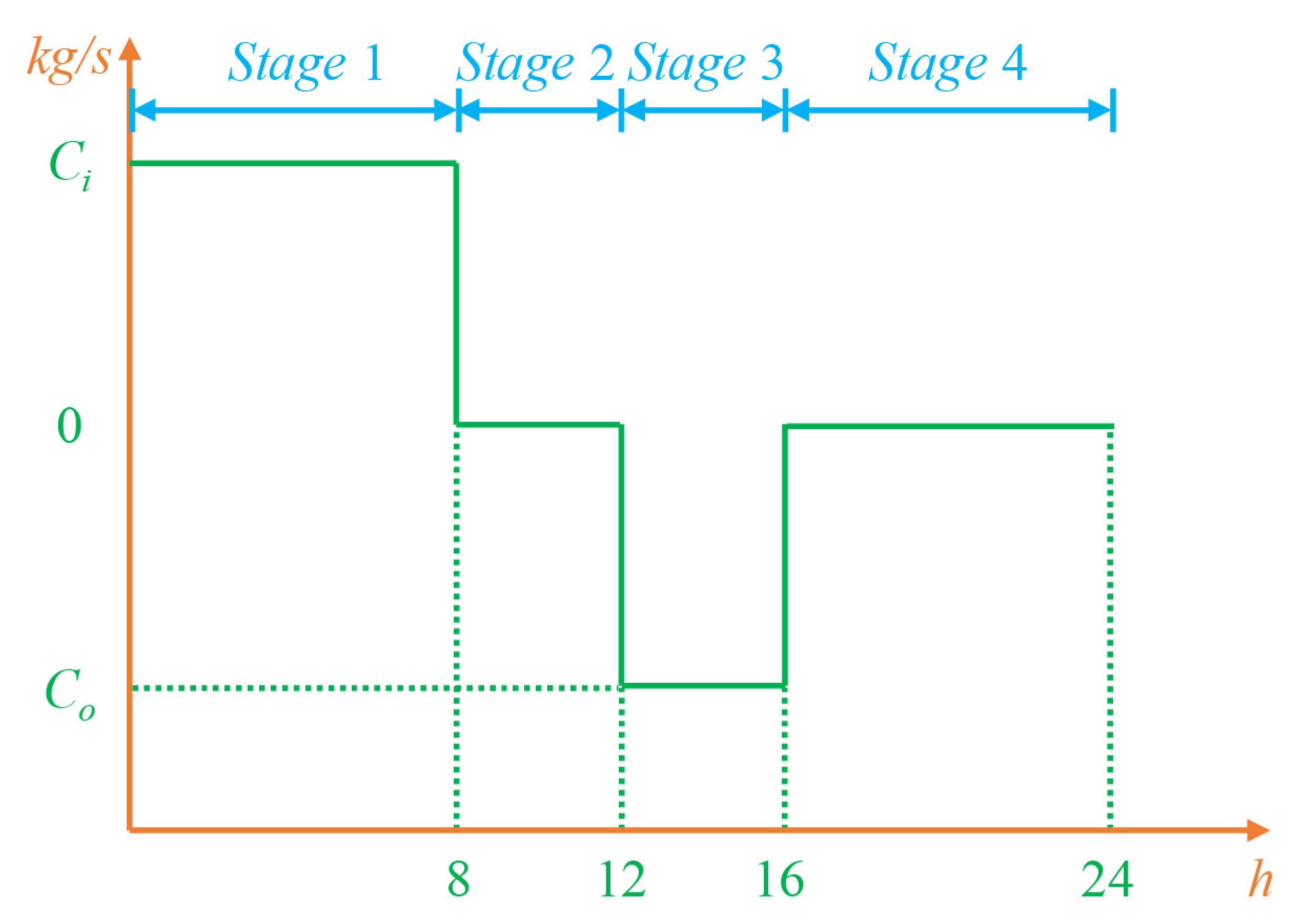
Figure 4 shows the geometric model for underground hydrogen storage in a lined rock cavern in Southern Ontario, Canada. The geometric model was constructed and numerically implemented in COMSOL Multiphysics 6.2. To position the cavern within the relatively intact lower member of the Cobourg Formation, its centre is placed at a depth of 670 m. The model domain is 100 m × 100 m. The lined rock cavern is represented by a two–dimensional cross–section under the plane–strain assumption, corresponding to the middle section of a long cavern with a prescribed axial length Lc = 1000 m. The cavern volume is calculated by multiplying the cross–sectional area by Lc, while end effects along the cavern axis are neglected. A 10 m diameter circular cavern section is adopted as the base case and compared with an equal–area arched section. The charge–discharge mass flow rate profile is shown in Figure 5. The 24 h mass–flow–rate profile shown in Figure 5 is continuously repeated for 20 operating cycles (480 h in total) in all simulation cases. The initial gas pressure was set to 5 MPa, within the 3–15 MPa cushion–gas pressure range investigated in a recent thermodynamic study of hydrogen storage in LRCs, while the initial temperatures of the hydrogen and solid domains and the injection temperature were uniformly set to 293.15 K following the same reference [36]. The charging and discharging mass flow rates were set to 20 and 40 kg/s, respectively, and the 24 h operating schedule comprised 8 h of charging, 4 h of post–charging storage, 4 h of discharging, and 8 h of post–discharge storage, following the cyclic operating scheme used in a recent LRC hydrogen–storage model [27]. Because detailed dispatch schedules for commercial–scale hydrogen LRCs are not publicly available, the adopted daily profile represents a standardized high–frequency operating scenario rather than a direct reproduction of a specific facility. The engineering relevance of repeated cycling is supported by the HYBRIT pilot tests, which included frequent variations between high and low storage pressures.
Figure 4.
Geometric model and mesh discretization: (a) Geometric model; (b) mesh discretization.
Figure 5.
Charging and discharging mass flow rate curve for hydrogen storage in a lined rock cavern during one 24 h operating cycle.
The model comprises a sealing layer, concrete lining, and surrounding rock. The concrete lining and sealing layer are assigned thicknesses of 0.5 m and 0.02 m, respectively. The steel lining has high strength and high thermal conductivity and is commonly used as a gas–tight material in lined rock cavern gas storage structures. Fibre–reinforced plastic (FRP), with relatively low thermal conductivity and good deformation adaptability, is also regarded as a potential sealing material for high–pressure hydrogen storage in lined rock caverns. In the present model, the sealing layer is assumed to be perfectly gas–tight, and hydrogen leakage through the sealing layer, structural interfaces, and surrounding rock is neglected. Groundwater flow and pore–water–pressure effects are also not considered. Under identical geometry and operating conditions, the effects of steel and FRP sealing layers on gas temperature–pressure evolution and the mechanical behaviour of the surrounding rock are compared [20,22]. Accordingly, the comparison between steel and FRP in this study is restricted to their effects on heat transfer and short–term thermo–mechanical response and should not be interpreted as a complete assessment of their long–term suitability for hydrogen service. Material parameters for the sealing layer, concrete lining, and surrounding rock are determined from previous lined rock cavern experiments, numerical simulations, and the geological conditions of Southern Ontario [20,22,25]. The geological conditions, cavern surrounding materials, and surrounding rock properties are listed in Table 2 and Table 3.
Table 2.
Geological conditions and gas properties.
Table 3.
Properties of cavern surrounding materials and surrounding rock.
In the two–dimensional model, an in–plane horizontal stress of 22 MPa and a vertical stress of 18 MPa are applied to represent the stress state of the cavern under the regional in situ stress field. The horizontal stress is then varied to analyze the influence of in situ stress difference on stress redistribution around the cavern. Roller constraints are imposed on the bottom and right boundaries, and the mesh contains 42,140 elements. L1 and L2 are monitoring lines extending from the cavern centre in the vertical and horizontal directions, respectively. D1, D2, and D3 are monitoring points located in the sealing layer, concrete lining, and surrounding rock, respectively, at distances of 5.01 m, 5.27 m, and 6.26 m from the cavern centre.
3. Model Validation
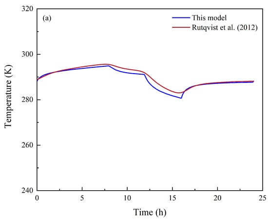
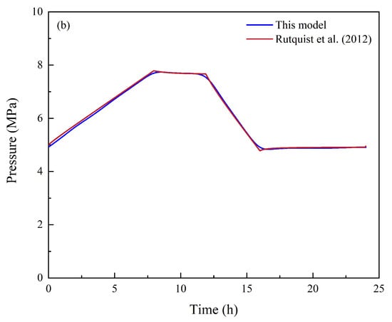
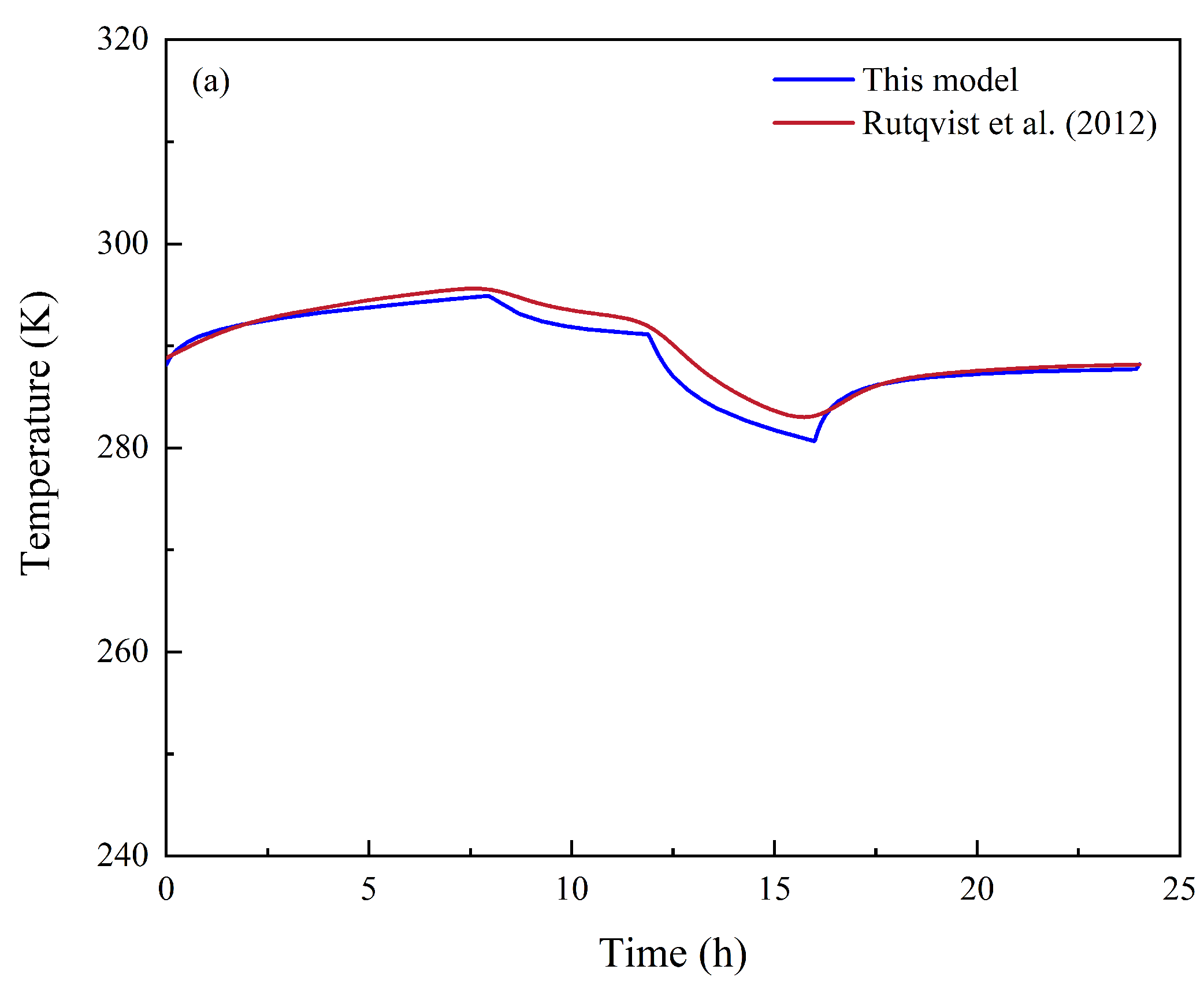
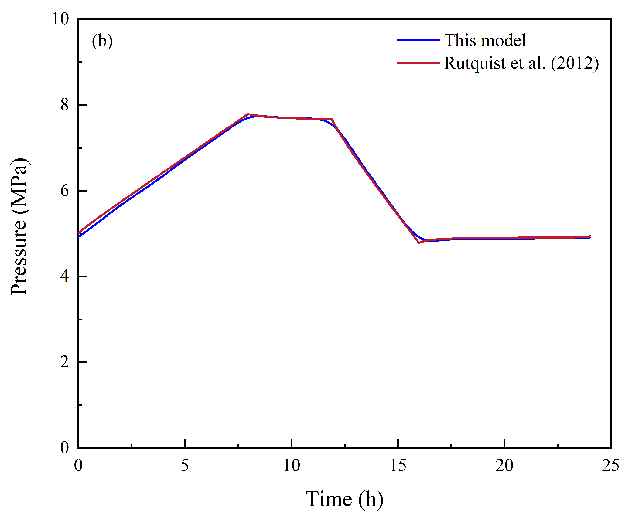
The proposed thermo–gas–mechanical coupling model is verified by benchmarking its results against Rutqvist et al.’s compressed-air energy storage model for a lined rock cavern [38]. Rutqvist et al. [38] used TOUGH–FLAC to develop a two–dimensional coupled model for compressed–air storage in a lined rock cavern and simulated cyclic operation with injection and withdrawal mass flow rates of 2.2 × 10⁻² kg/s and 4.4 × 10⁻² kg/s, respectively. In their model, the injected air temperature was 294.65 K, while the initial surrounding rock temperature and gas pressure were 286.15 K and 5 MPa, respectively. Table 4 summarizes the parameters of the rock and lining materials.
Table 4.
Numerical simulation parameters for the validation model.
The geometry and material parameters and boundary conditions adopted for validation are kept consistent with the reference model. The model domain is 25 m × 25 m and is discretized into 25,092 triangular elements. A vertically downward boundary load is applied on the top boundary, while roller supports are assigned to the other three boundaries. These boundary conditions differ from those used in the Southern Ontario model in Figure 4 because the validation case reproduces the reference benchmark, whereas the application model adopts the regional in situ stresses and corresponding constraints. Figure 6 shows that the spatially uniform cavern–gas temperature and pressure predicted by the present model agree well with the TOUGH–FLAC results. The model captures the main thermodynamic features, including pressurization and heating during charging, depressurization and cooling during discharging, and gradual adjustment during storage. These results demonstrate the capability of the proposed model to capture gas thermodynamic behaviour and thermo–mechanical interactions with the surrounding rock during lined rock cavern storage.
Figure 6.
Model validation against the results of Rutqvist et al. [38]: (a) Temperature; (b) pressure.
4. Simulation Results
4.1. Multi–Field Coupling Response of Hydrogen Storage in the Cavern
4.1.1. Thermodynamic and Heat–Transfer Response
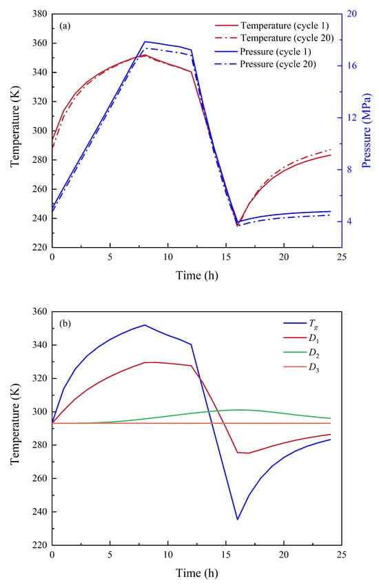
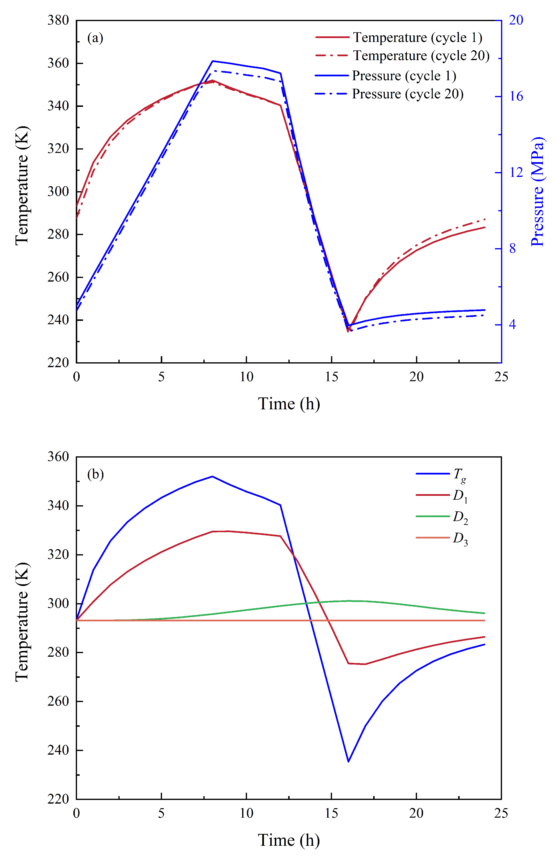
Figure 7a shows the temporal evolution of the spatially uniform cavern–gas temperature and pressure during the first operating cycle under base–case conditions. During the charging–storage–discharging cycle, both gas temperature and pressure exhibit clear stage–dependent evolution. During the charging stage, the continuous increase in hydrogen mass compresses the gas inside the cavern and increases its internal energy, resulting in a simultaneous rise in temperature and pressure. During the storage stage, although the gas mass remains unchanged, gas–wall thermal exchange continues. The heat generated by gas compression is gradually transferred to the sealing layer, concrete lining, and surrounding rock, leading to a slow decrease in gas temperature and pressure. During the discharging stage, the gas mass decreases rapidly, and gas expansion occurs, causing a significant drop in temperature and pressure. During the subsequent storage stage, thermal energy supplied by the cavern wall materials and surrounding rock gradually reheats the low–temperature hydrogen, promoting gas temperature–pressure recovery.
Figure 7.
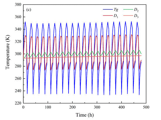
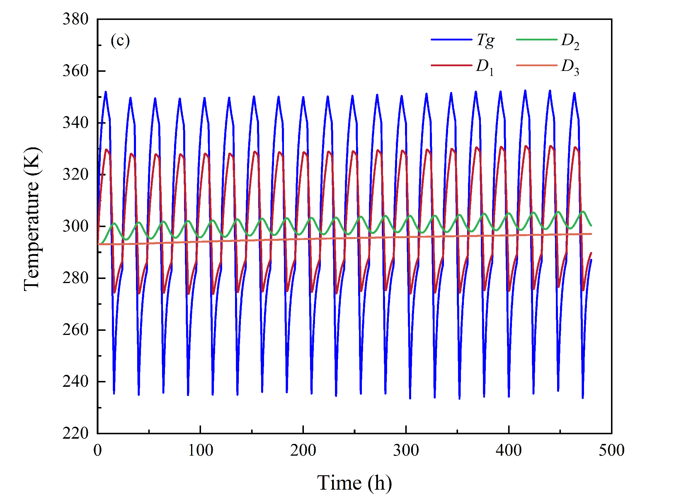
Temporal variations in hydrogen temperature, hydrogen pressure, and temperature at typical monitoring points during the first operating cycle: (a) Temperature and pressure; (b) temperature at typical monitoring points during the first operating cycle; (c) temperature evolution over 20 operating cycles.
Figure 7b further compares the spatially uniform bulk cavern–gas Tg, calculated from the global gas–energy balance, with the solid temperatures at monitoring points D1, D2 and D3. The sealing layer is in direct contact with the gas inside the cavern, and the temperature at D1 responds most sensitively to the charging and discharging processes, showing an overall trend consistent with the gas temperature. Temperature variation at D2 in the concrete lining is much smaller than at D1 and shows a noticeable time lag. During post–charging storage, continued gas–to–solid heat transfer allows the concrete lining temperature to keep rising. The monitoring point D3 in the surrounding rock is located farther from the cavern wall and shows only a small temperature variation, indicating that the thermal disturbance is mainly concentrated near the cavern wall during the first cyclic operation. Overall, temperature fluctuations attenuate and peak temperatures occur later with increasing distance from the cavern wall. This indicates that thermal disturbance during hydrogen storage in lined rock caverns has significant spatial attenuation and temporal lag characteristics.
To evaluate the influence of repeated operation on cavern thermodynamic response, Figure 7a compares the spatially uniform cavern–gas temperature and pressure during the first and 20th operating cycles. Both cycles exhibit similar stage–dependent evolution, indicating that repeated charging and discharging do not alter the basic thermodynamic response pattern. Compared with the first cycle, the gas temperature in the 20th cycle is slightly lower during charging and discharging but slightly higher during post–discharge storage. This reflects the effect of the inherited wall–temperature field, which enhances heat dissipation during high–temperature stages and promotes reheating after discharging. Under the same prescribed mass–flow conditions, the gas pressure in the 20th cycle is also slightly lower overall, consistent with the lower gas–temperature level. Therefore, 20 repeated cycles mainly adjust the cyclic thermal state and temperature–pressure baseline, rather than fundamentally changing the response pattern.
Figure 7c presents the temperature evolution of the cavern gas and the sealing–lining–rock system over 20 consecutive operating cycles. The bulk gas temperature Tg exhibits pronounced periodic fluctuations, whereas the temperature at D1 follows the same cyclic trend with a reduced amplitude. The fluctuation at D2 is further attenuated and delayed, while D3 shows almost no short–period fluctuation and only a gradual temperature increase. With increasing cycle number, the fluctuation amplitudes of Tg and D1 remain generally stable, whereas the mean temperatures at D2 and D3 gradually increase. This indicates that repeated operation produces cumulative heat transfer from the cavern gas and near–wall structure toward the deeper surrounding rock, confirming the spatial attenuation and temporal lag of heat propagation in the cavern system.
4.1.2. Mechanical Response and Stress Redistribution
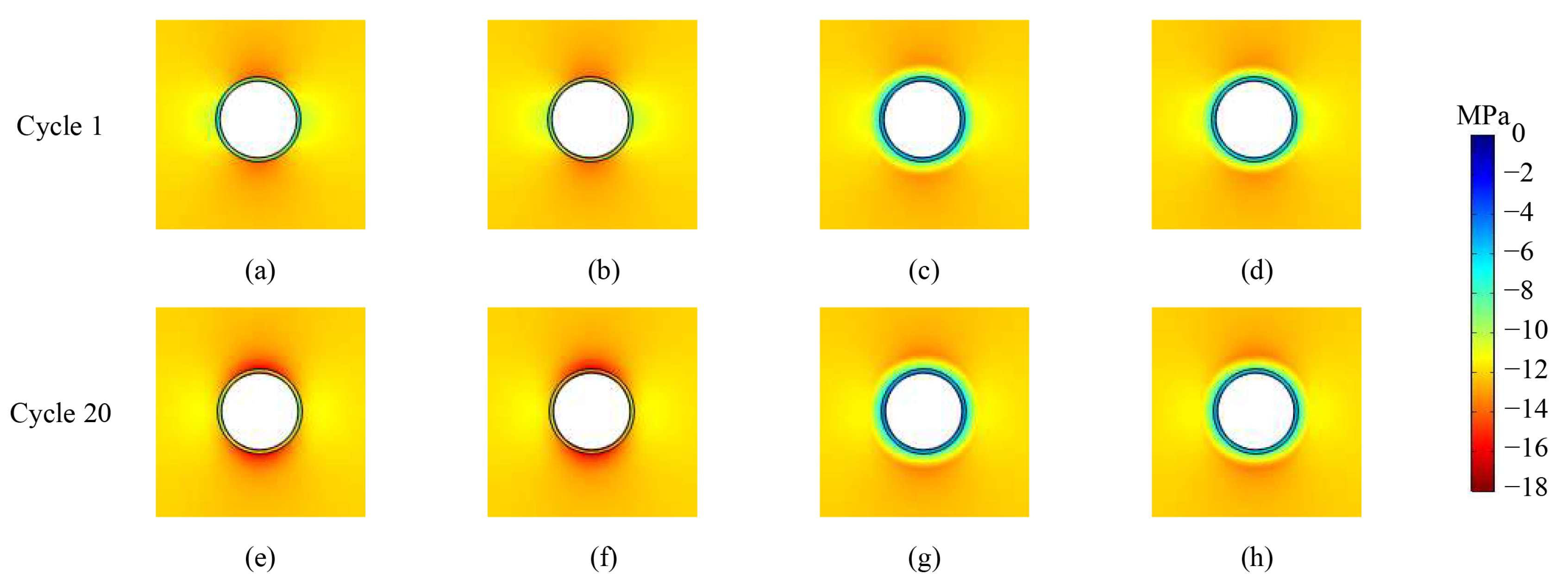
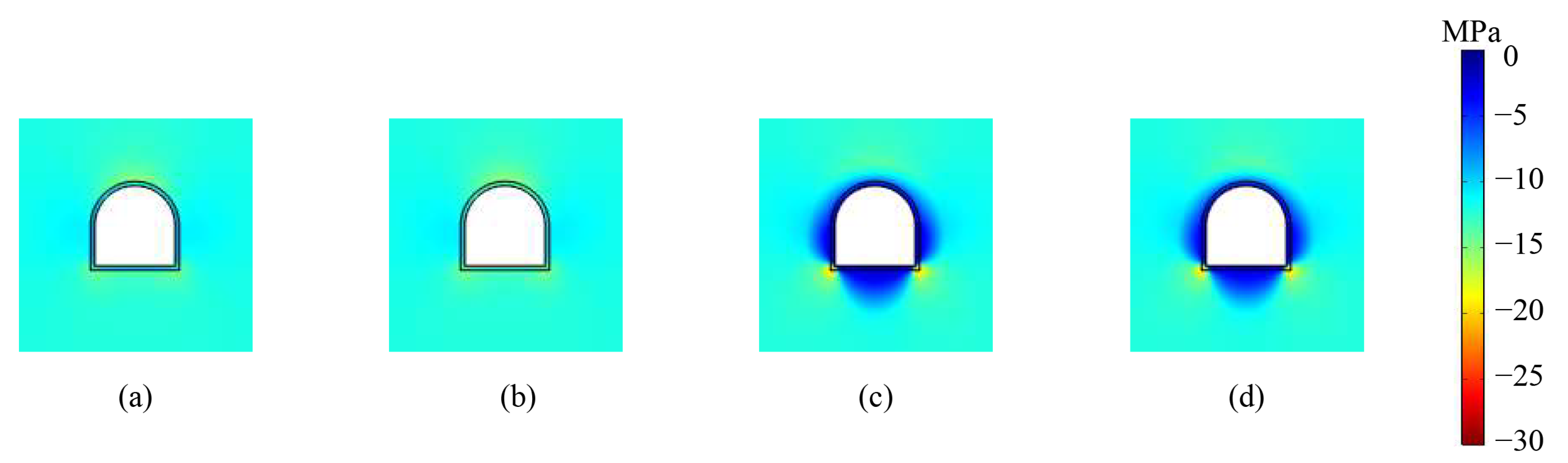
Figure 8 presents the first principal stress distribution around the cavern at selected stages of the first operating cycle. Overall, the first principal stress around the cavern is dominated by a compressive stress state, with evident compressive stress concentration near the crown and invert. The stress distributions at 8 h and 12 h are relatively similar, indicating that, during the short–term storage period after charging, the stress adjustment around the cavern remains limited despite the gradual changes in gas temperature and pressure. At 16 h, following discharging, the reduced internal pressure weakens radial support at the cavern wall. As a result, the first principal stress near the cavern wall shifts toward 0 MPa, indicating compressive stress release, and a distinct annular stress–release zone forms near the cavern wall. At 24 h, the annular stress–release zone near the cavern wall becomes weaker, but a certain degree of stress redistribution remains around the cavern. These results suggest that cyclic pressure–temperature fluctuations jointly control stress redistribution in the lining–surrounding–rock system. In particular, the end of the discharging stage, when the internal pressure is relatively low and the temperature drop is pronounced, represents a critical period during which the first principal stress near the cavern wall changes significantly. This stage should therefore be given particular attention in the safety assessment of cyclic hydrogen storage in lined rock caverns.
Figure 8.
Distribution characteristics of the first principal stress around the circular cavern: (a) 8 h of cycle 1; (b) 12 h of cycle 1; (c) 16 h of cycle 1; (d) 24 h of cycle 1; (e) 8 h of cycle 20; (f) 12 h of cycle 20; (g) 16 h of cycle 20; (h) 24 h of cycle 20.
Figure 8e–h further compares the first–principal–stress distributions at the corresponding stages of the first and 20th operating cycles. After 20 repeated charging and discharging cycles, the overall spatial pattern of the first principal stress remains essentially unchanged, with compressive–stress concentration continuing to occur near the cavern crown and invert and relatively lower stress levels appearing along the sidewalls. Compared with the first cycle, the compressive–stress concentration near the crown and invert becomes slightly more pronounced during the charging and post–charging storage stages of the 20th cycle. At the end of discharging, a distinct annular stress–release zone still develops near the cavern wall, while the surrounding stress field shows only limited local adjustment. This indicates that the inherited thermal state from the preceding cycles modifies the magnitude of the local thermo–mechanical response but does not alter the dominant stress distribution pattern controlled by cavern geometry and the in situ stress field. Overall, repeated operation causes a moderate redistribution of the near–wall stress state rather than continuous stress accumulation under the present linear–elastic and non–degrading material assumptions.
4.2. Effect of Cavern Geometry
Figure 9 presents the first–principal–stress distribution around the arched cavern at selected stages of the 20th operating cycle. Overall, the large region of surrounding rock far from the cavern remains dominated by compressive stress, whereas the stress near the cavern wall is significantly affected by the changes in internal pressure and cavern geometry. At 8 h and 12 h, the region around the cavern is still generally under compression, and the distribution of the first principal stress is relatively smooth, with no obvious local high–value zone. At 16 h, after discharging, the internal pressure decreases significantly and the supporting effect of the gas pressure on the cavern wall weakens. Meanwhile, cooling by the gas induces thermal contraction in the lining and near–wall region. As a result, the first principal stress near the sidewalls, floor, and wall–floor corners shifts toward larger values, forming distinct high–value zones. In these local regions, compressive stress release occurs, and the stress state tends to transition toward tension. By 24 h, with heat transfer from the surrounding rock and gradual recovery of the internal pressure, the local high–value zones become weaker; however, notable stress disturbance remains near the wall–floor corners and floor. Compared with the circular cavern, the arched cavern is more strongly affected by the straight sidewalls, flat floor, and geometric transition zones. Local high–value zones of first principal stress are more likely to occur near the sidewall–floor connection, indicating that this region is a potential weak zone that requires particular attention during cyclic hydrogen storage in arched lined rock caverns.
Figure 9.
Distribution characteristics of the first principal stress around the arched cavern of the 20th operating cycle: (a) 8 h; (b) 12 h; (c) 16 h; (d) 24 h.
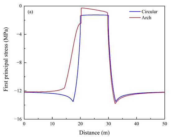
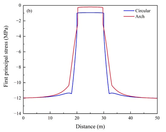
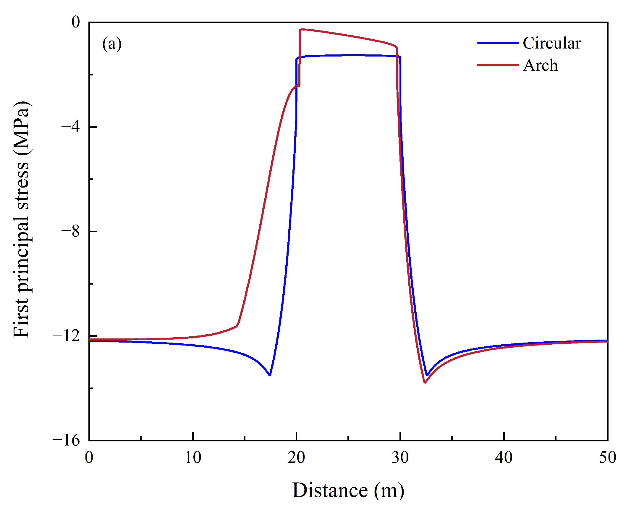
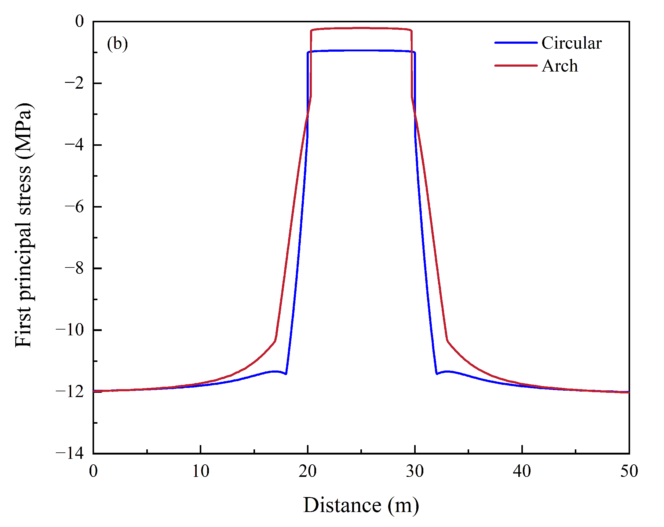
Figure 10a,b show the distributions of the first principal stress along the L1 and L2 monitoring lines at 16 h, respectively. The results indicate that cavern geometry primarily affects stress distribution within roughly 10 m of the cavern wall. Away from the cavern, the first principal stress for both cavern geometries gradually returns to the far–field stress state. Along the vertical monitoring line L1, a clear local compressive stress concentration appears above the crown of the circular cavern, whereas the first principal stress near the crown of the arched cavern is closer to 0 MPa. Beneath the floor, both caverns show compressive stress concentrations of approximately −12 to −13 MPa, with the arched cavern showing slightly stronger compression. Along the horizontal monitoring line L2, the stress distribution is generally symmetric. Near the arched cavern sidewalls, the first principal stress approaches 0 MPa and deviates from the far–field state over a broader zone, indicating stronger stress release and a larger lateral disturbance induced by the straight sidewall geometry. In contrast, the stress variation around the circular cavern is more localized near the cavern wall. Overall, the circular cavern causes a more limited stress disturbance, whereas the arched cavern exhibits compressive–stress release near the crown and sidewalls and concentration near the floor and wall–floor corners. Therefore, the stress distribution around the arched cavern is more non–uniform, and its potential weak zones are mainly located near the wall–floor corners and adjacent floor region.
Figure 10.
Distribution of the first principal stress along the L1 and L2 monitoring lines during the 20th operating cycle: (a) L1; (b) L2.
4.3. Effect of Sealing Material
Steel has high strength, stiffness, and thermal conductivity and is commonly used as a gas–tight structural material in lined rock caverns. In contrast, FRP has lower thermal conductivity and elastic modulus, showing stronger thermal insulation capacity and deformation adaptability. Therefore, under the same cavern structure and hydrogen storage operating conditions, this section compares the effects of steel and FRP sealing layers on the gas thermodynamic state, solid heat transfer, and lining stress response.
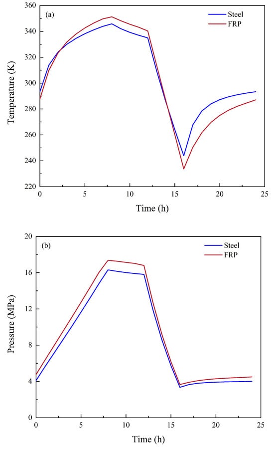
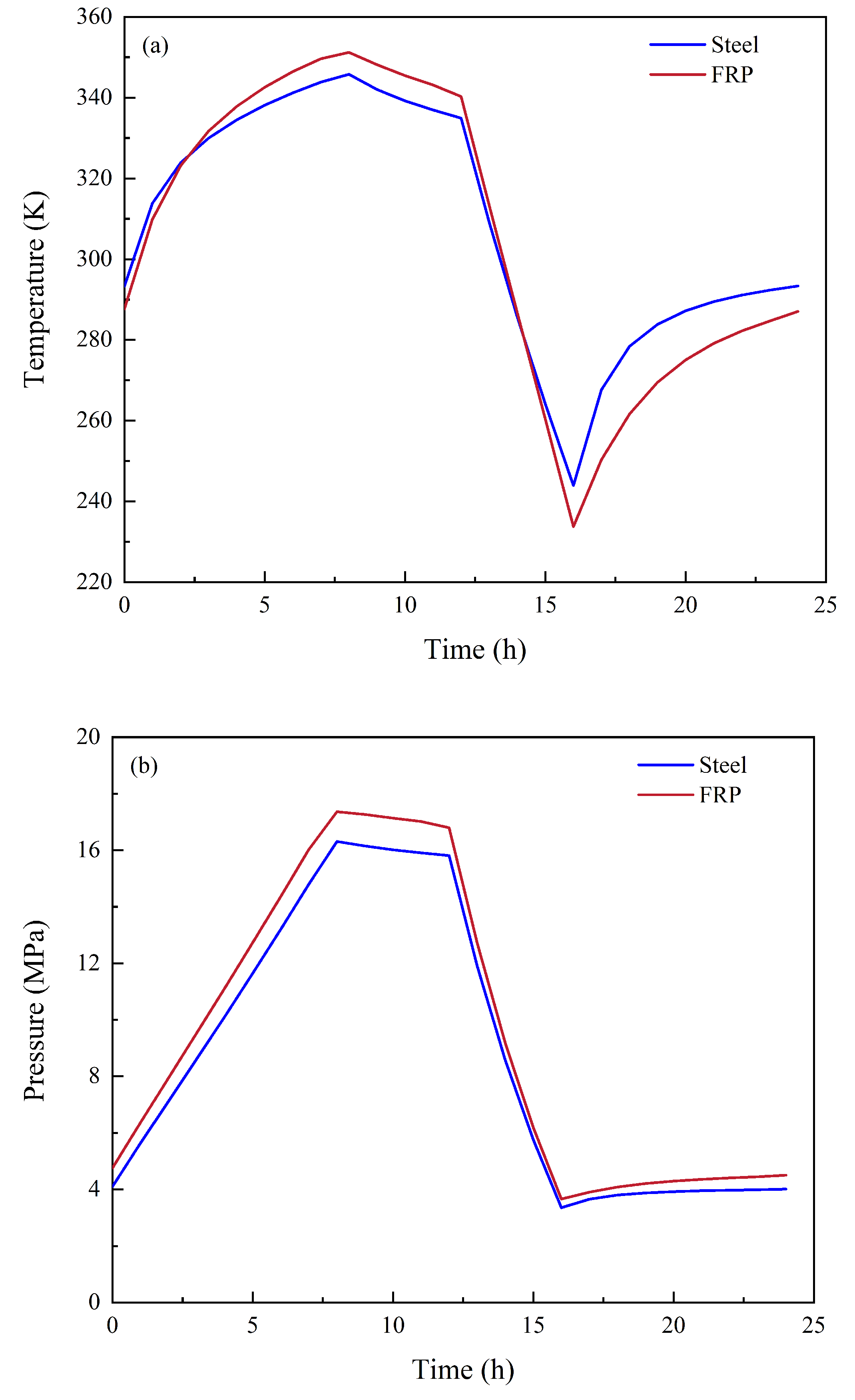
Figure 11 shows hydrogen temperature–pressure evolution for different sealing materials during the 20th operating cycle. During charging, the FRP–sealed cavern reaches a maximum hydrogen temperature of approximately 351.20 K, exceeding the 345.78 K obtained for the steel–sealed case. By the end of discharging, the FRP–sealed cavern reaches a minimum hydrogen temperature of approximately 233.73 K, below the 243.94 K obtained for the steel–sealed case. These results indicate that the lower thermal conductivity of FRP weakens the heat exchange between hydrogen, concrete lining, and surrounding rock, thereby intensifying gas temperature fluctuations during charging and discharging. In contrast, the higher thermal conductivity of the steel sealing layer accelerates heat transfer to the concrete lining and surrounding rock during charging and promotes heat return to the cooled hydrogen during discharging. As a result, the steel sealing layer reduces the amplitude of gas temperature variation. For gas pressure, Figure 10b shows broadly similar evolution trends for the two sealing materials. The peak pressure in the FRP case is approximately 17.36 MPa, slightly higher than that in the steel case, 16.31 MPa, mainly because of the higher gas temperature during charging in the FRP case. At the end of discharging, the pressure in both cases decreases to approximately 3.66 MPa and 3.35 MPa, respectively, and subsequently recovers to 4.50 MPa and 4.01 MPa, respectively. Overall, the sealing material mainly affects gas temperature fluctuation by changing the heat transfer capacity of the cavern wall, while its influence on gas pressure evolution is relatively limited.
Figure 11.
Variations in gas temperature and pressure during the 20th operating cycle under different sealing materials: (a) Temperature; (b) pressure.
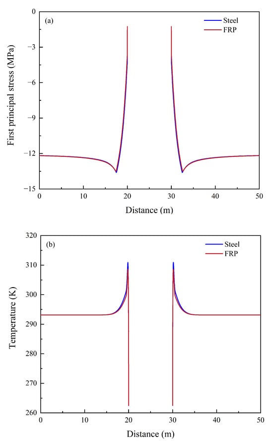
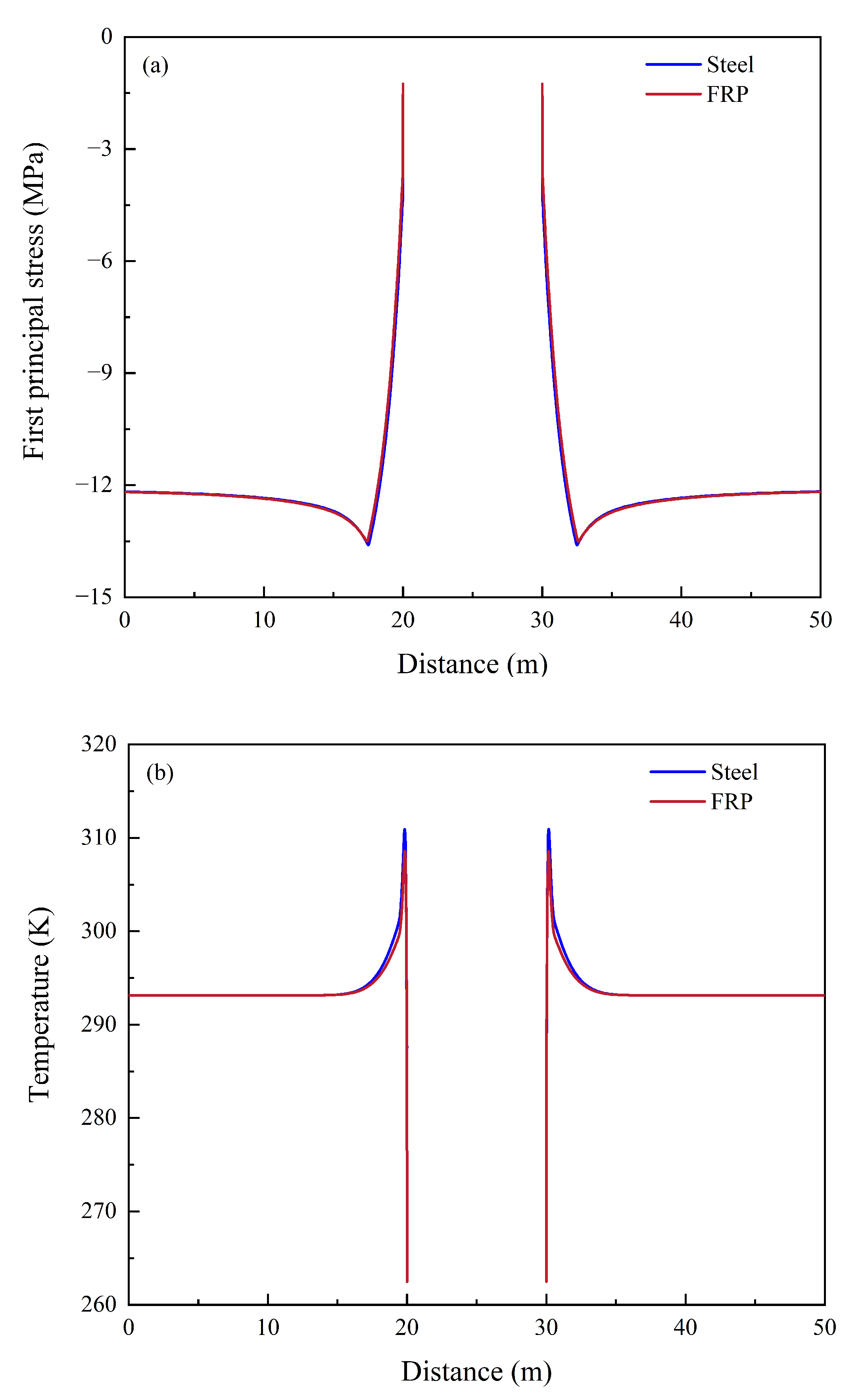
Figure 12 shows the distributions of the first principal stress and solid temperature along the L1 monitoring line at 16 h under different sealing materials during the 20th operating cycle. The first principal stress results indicate that the curves for the steel and FRP cases almost overlap in the upper and lower surrounding rock, and both recover to approximately −12.20 MPa away from the cavern wall. The near–wall region maintains a first principal stress of approximately −13.20 MPa, indicating a compressive state. The difference in stress distribution between the two sealing materials is small, suggesting that the influence of sealing material on the overall stress field of the surrounding rock is mainly limited to the sealing layer and its adjacent region near the concrete lining, with limited influence on the far–field stress distribution. The temperature distribution results show that, away from the cavern, the solid temperatures in both cases approach the initial temperature of 293.15 K, whereas clear differences occur near the cavern wall. High thermal conductivity enables the steel sealing layer to transfer heat from the concrete lining and surrounding rock to cooled hydrogen by the end of discharging, maintaining a relatively high near–wall temperature. In contrast, the FRP sealing layer provides stronger thermal insulation, reducing thermal exchange between the cavern gas and the lining–surrounding–rock system. Consequently, its inner surface temperature decreases more significantly, while the thermal disturbance propagating into the surrounding rock is weaker. These results indicate that sealing material has limited influence on overall surrounding–rock stress distribution but strongly modifies near–wall thermal gradients and heat transfer, thereby affecting gas temperature fluctuation amplitude.
Figure 12.
Distribution of the first principal stress and solid temperature along the L1 monitoring line under different sealing materials during the 20th operating cycle: (a) First principal stress; (b) temperature.
5. Discussion
5.1. Effect of In Situ Stress Difference on the Cavern Stress State
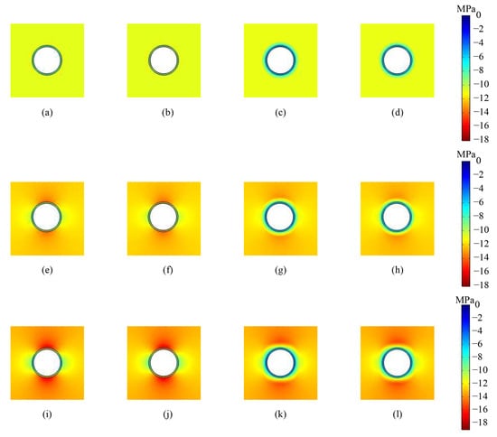
The preceding results indicate that cavern geometry mainly controls the locations of local stress concentration, whereas the sealing material primarily affects heat transfer and near–wall stress adjustment. However, these engineering factors operate under a given in situ stress condition, and the overall stress level during cavern excavation and cyclic hydrogen storage is still controlled by the regional stress state. To further reveal the control of the geological stress background on cavern stability, this section compares the stress responses under in–plane horizontal stresses of 18, 22, and 26 MPa, with emphasis on the effects of stress difference on the magnitude, distribution range, and potential weak zones of the first principal stress.
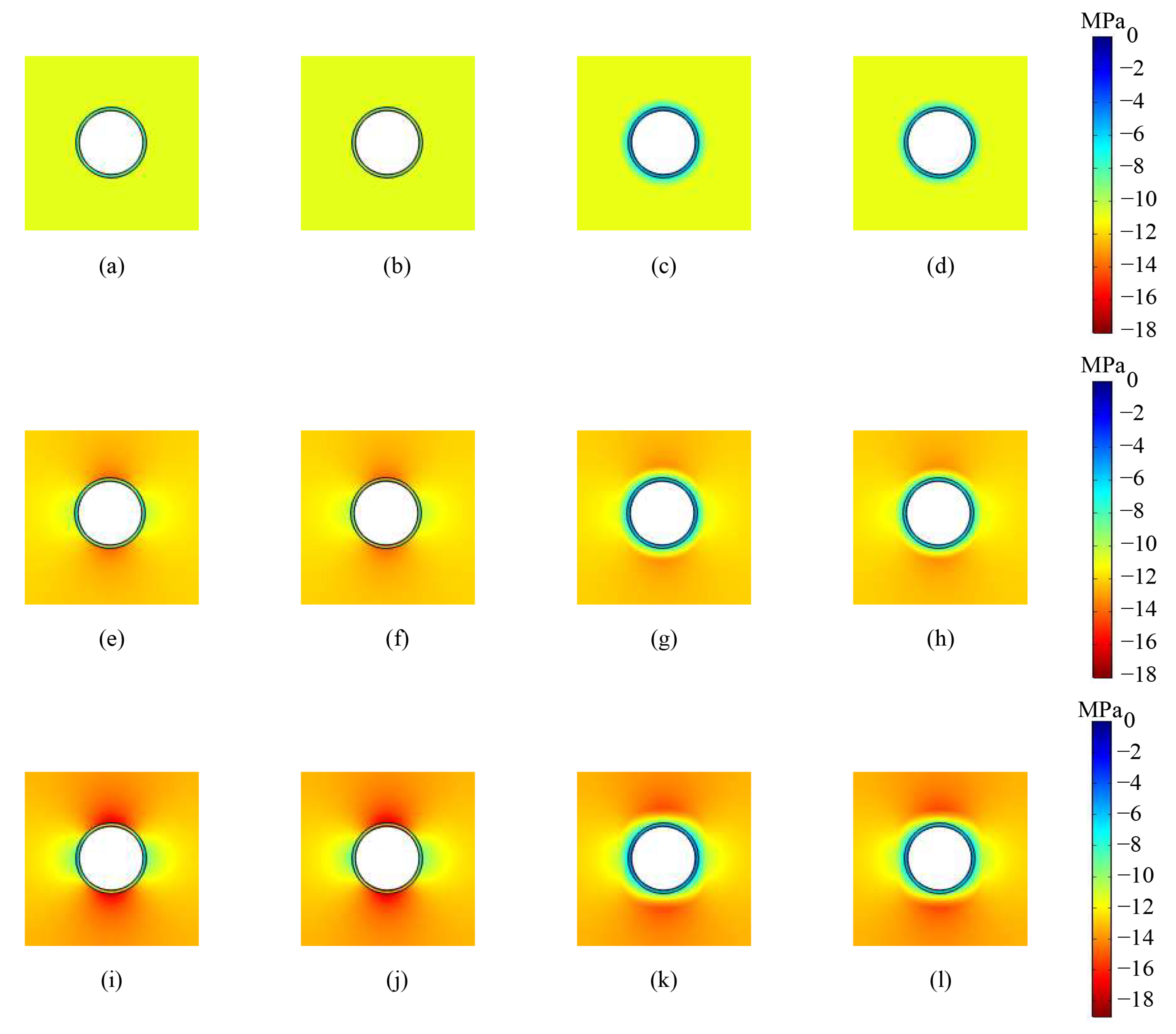
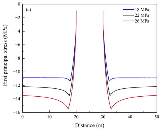
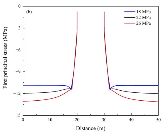
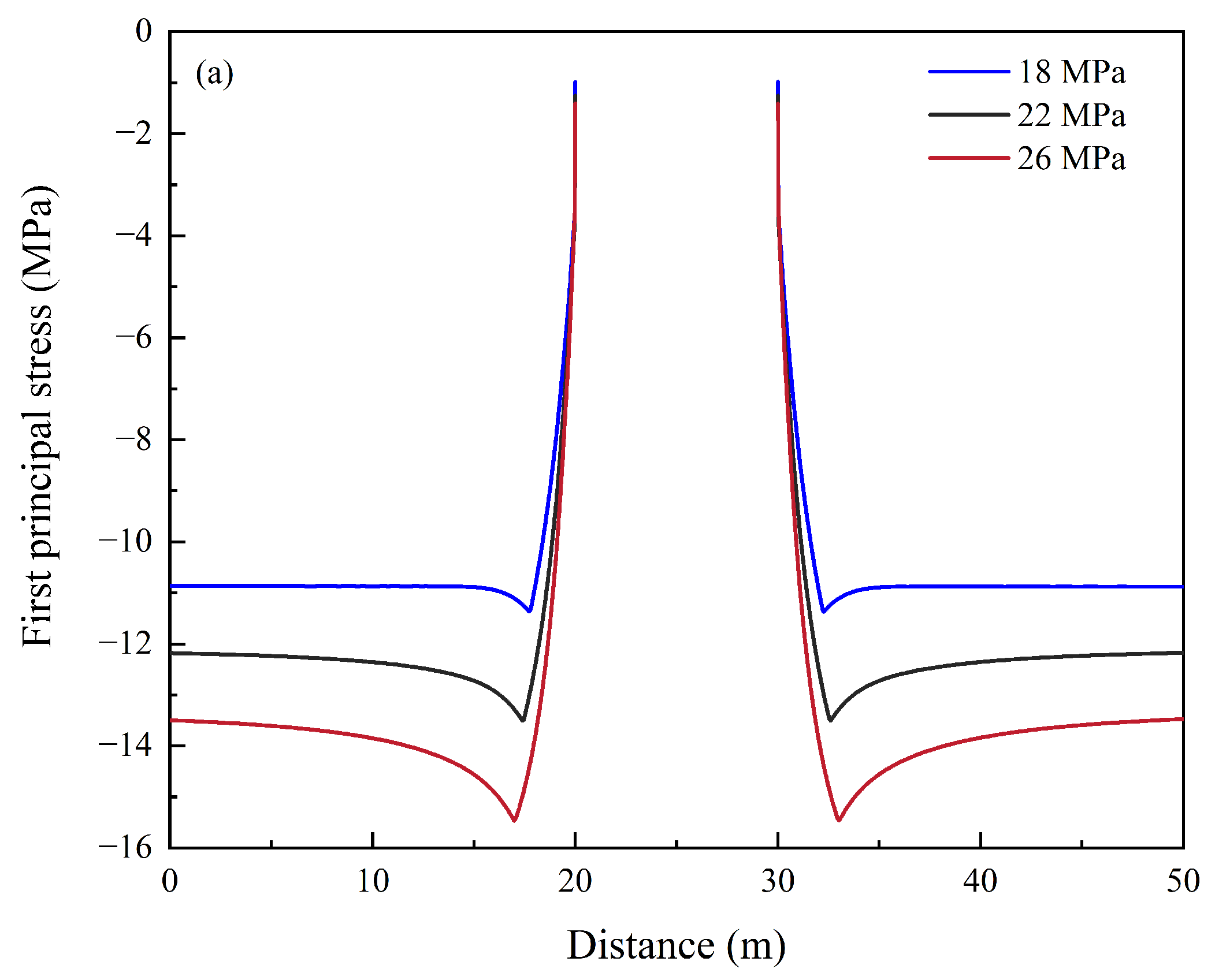
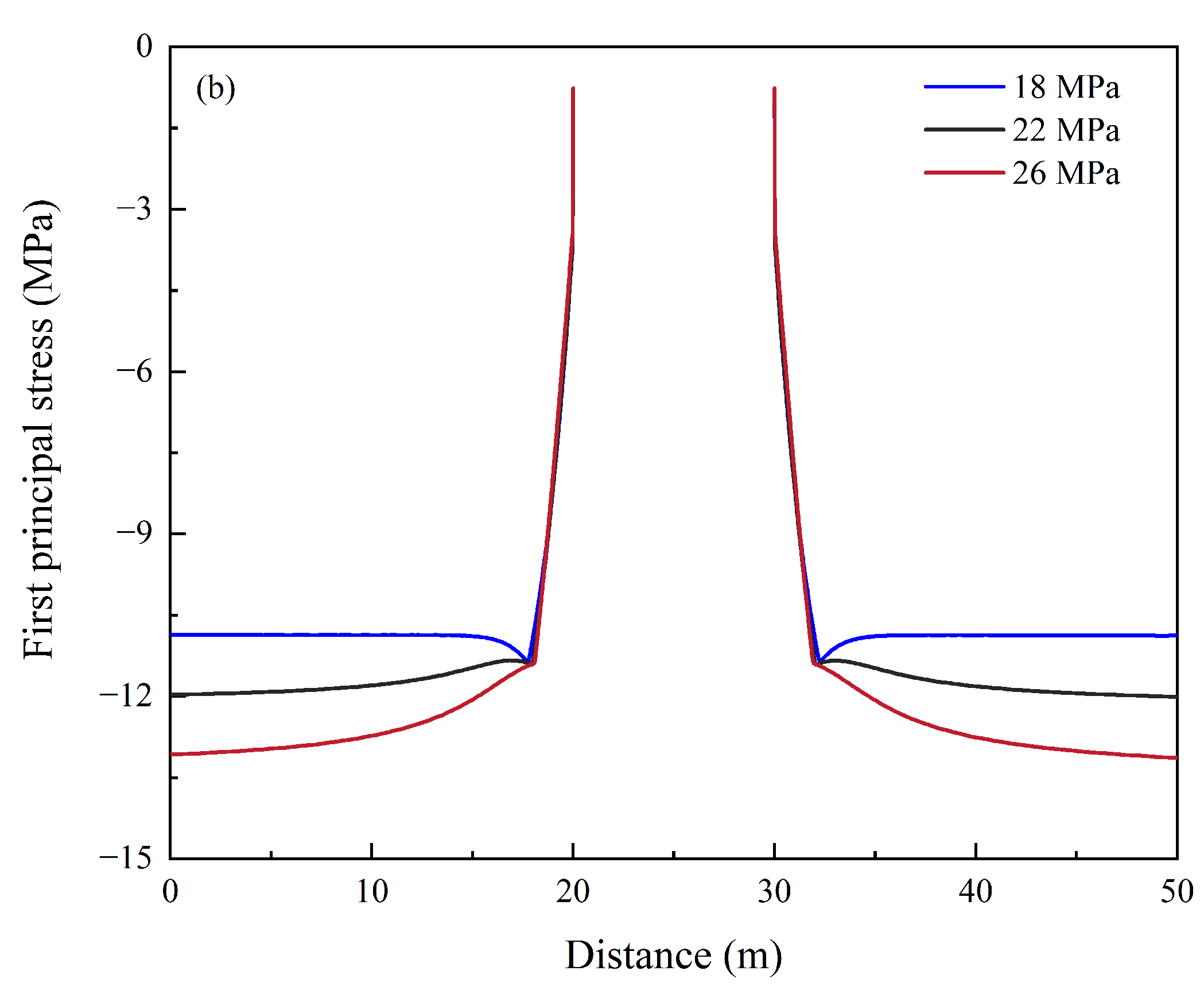
Figure 13 presents first–principal–stress distributions around the cavern under different horizontal stress conditions during the 20th operating cycle. Overall, the large region of surrounding rock around the cavern remains in a compressive stress state. When the horizontal stress is 18 MPa, equal to the vertical stress, the stress distribution around the cavern is nearly annular and relatively uniform, with weak directionality. As the horizontal stress increases to 22 MPa, compressive stress intensifies near the cavern crown and invert, whereas it is relatively released near the two sidewalls. When the horizontal stress further increases to 26 MPa, this non–uniform characteristic becomes more pronounced: the compressive stress concentration zones at the crown and invert expand, and the stress–release zones near the sidewalls become more evident. Particularly at 16 h, after discharging, the first principal stress near the cavern wall clearly shifts toward 0 MPa, indicating the formation of an annular compressive stress–release zone. During the subsequent storage stage, this release zone gradually weakens, but a certain degree of stress disturbance remains around the cavern. These results indicate that increasing horizontal stress enhances stress redistribution between the crown, invert, and sidewalls, causing the cavern stress state to gradually change from a nearly uniform distribution to a clearly directional pattern.
Figure 13.
Distribution of the first principal stress around the cavern under different horizontal stress conditions during the 20th operating cycle: (a) 8 h (18 MPa); (b) 12 h (18 MPa); (c) 16 h (18 MPa); (d) 24 h (18 Mpa); (e) 8 h (22 MPa); (f) 12 h (22 MPa); (g) 16 h (22 MPa); (h) 24 h (22 MPa); (i) 8 h (26 MPa); (j) 12 h (26 MPa); (k) 16 h (26 MPa); (l) 24 h (26 MPa).
The monitoring results along L1 and L2 in Figure 14 further show that, at the end of discharging, i.e., 16 h, the directional difference in the first principal stress around the cavern becomes more significant as the horizontal stress increases from 18 to 26 MPa during the 20th operating cycle. Along the vertical path, the first principal stress near the crown and invert decreases from approximately −11 MPa to approximately −15 MPa, indicating that the compressive stress concentration in the crown and invert regions is significantly enhanced with increasing horizontal stress, and that its influence extends deeper into the surrounding rock. Along the horizontal path, from the far field toward the sidewall, the first principal stress under higher horizontal stress conditions gradually changes from a stronger compressive state to approximately −11 MPa, indicating more pronounced compressive stress release near the sidewall. Therefore, increasing horizontal in situ stress does not cause all regions around the cavern to experience synchronous compression enhancement. Instead, it promotes load redistribution from the sidewalls toward the crown and invert, ultimately resulting in stronger compressive stress concentration at the crown and invert and relative stress release near the sidewalls. This result indicates that in situ stress difference not only determines the stress level around the cavern but also controls the location of potential weak zones and the direction of stress disturbance.
Figure 14.
Distribution of the first principal stress along the L1 and L2 monitoring lines under different horizontal stress conditions during the 20th operating cycle: (a) L1; (b) L2.
5.2. Multi–Field Coupling Mechanism
Thermo–gas–mechanical behaviour during hydrogen storage in lined rock caverns is jointly governed by engineering design factors and regional geological conditions. The charge–discharge operation alters cavern hydrogen temperature–pressure conditions, modifying the thermal field through gas–wall heat exchange and the mechanical field through internal pressure loading. Meanwhile, cavern volume variation caused by deformation of the lining and surrounding rock feeds back to regulate the gas state. Cavern geometry mainly controls the load transfer path and local weak zones. The circular cavern shows a relatively uniform stress distribution, whereas the arched cavern is more prone to high first–principal–stress zones near the sidewall–floor connection and wall–floor corners. The sealing material mainly affects gas temperature fluctuation through its thermal conductivity. The steel sealing layer enhances heat exchange and reduces the amplitude of temperature variation, whereas the FRP sealing layer provides stronger thermal insulation but intensifies gas temperature fluctuation. In situ stress difference further controls the direction of stress redistribution around the cavern. Increasing horizontal in situ stress enhances compressive stress concentration at the crown and invert, while the sidewall region exhibits compressive stress release relative to the far–field stress state. Therefore, hydrogen–storage stability in lined rock caverns is controlled not by a single factor but by the coupled influence of cavern geometry, sealing material, and in situ stress on heat transfer, load transfer, and stress redistribution.
5.3. Material Compatibility and Long–Term Durability
The present results indicate that the relatively high thermal conductivity of the steel sealing layer can moderate cavern–gas temperature fluctuations by facilitating heat transfer between the stored hydrogen, concrete lining, and surrounding rock. However, this heat–transfer effect does not by itself demonstrate superior long–term suitability for hydrogen containment. In susceptible steels, hydrogen ingress can reduce ductility, fracture toughness, and fatigue resistance [17,18,39]. The extent of degradation is governed by the steel grade and microstructure, hydrogen pressure and temperature, stress state, cyclic loading conditions, weld quality, and residual stress [17,18]. Welded joints, heat–affected zones, geometric discontinuities, and regions experiencing relatively large cyclic strains therefore require particular attention. Engineering design should rely on fracture and fatigue properties measured under representative high–pressure hydrogen environments rather than solely on material properties obtained in air [17,39].
Under the intact–sealing–layer assumption adopted in this study, the concrete lining and any embedded reinforcement are not directly exposed to the stored hydrogen. Nevertheless, local liner defects, weld cracking, or hydrogen permeation could expose reinforcement and adjacent structural components to hydrogen and, where present, moisture, potentially promoting corrosion or other forms of material degradation [17,18]. Hydrogen compatibility should also be considered for associated piping, valves, compressors, seals, and welded connections. FRP systems are not subject to metallic hydrogen embrittlement, but their long–term performance may still be governed by hydrogen permeability, polymer ageing, matrix cracking, fibre–matrix interfacial degradation, rapid–decompression damage, and cyclic thermo–mechanical fatigue [40,41]. Therefore, the steel–FRP comparison presented in this study is limited to heat–transfer performance and short–term thermo–mechanical response. Complete material qualification would require material–specific hydrogen permeation tests, mechanical testing under high–pressure hydrogen exposure, and long–term cyclic durability assessment [40,41].
5.4. Engineering Applicability, Risk and Deployment Considerations
Table 5 indicates that no single hydrogen storage option is universally optimal. Salt caverns generally provide the most favourable combination of cost, storage capacity, and cycling flexibility where suitable salt formations are available. Depleted gas reservoirs offer very large storage capacity and may benefit from existing infrastructure, but their performance and safety are strongly influenced by reservoir heterogeneity, cushion–gas requirements, legacy wells, and hydrogen–rock–fluid interactions. Compressed gas tanks are highly modular and readily inspected, but the requirement for additional high–pressure vessels limits their economic scalability. LRCs generally require higher initial construction expenditure than salt caverns and depleted gas reservoirs because of rock excavation, concrete lining, and gas–tight sealing; however, their engineered geometry and containment system provide greater design and monitoring control.
Table 5.
Comparison of hydrogen storage options in terms of cost, safety, and scalability.
Therefore, LRCs should be regarded as a complementary rather than universally superior hydrogen storage option in Southern Ontario. Salt caverns may be preferred where suitable salt formations are present, depleted gas reservoirs may be advantageous for very large seasonal storage, and compressed tanks remain appropriate for smaller or short–duration applications. LRCs are particularly relevant where competent low–permeability rock is available and where controllable cavern geometry, engineered containment, and repeated injection–withdrawal operation are prioritized.
Beyond the comparative safety characteristics summarized in Table 5, the safe operation of an LRC depends on the integrity of the sealing liner, interfaces, surrounding rock, and associated operating system. The present results indicate that the end of the discharging stage represents a relatively critical operating period because the simultaneous reduction in gas pressure and temperature induces pronounced near–wall stress redistribution. For arched caverns, the wall–floor transition regions also require particular attention because geometric transitions promote localized stress concentration. The main engineering risks therefore include liner or weld degradation, interface opening, surrounding–rock damage, operational overpressure, hydrogen leakage and subsequent fire or explosion following ignition, as well as liner and rock–mass damage induced by seismic events. These risks may be reduced through hydrogen–compatible material selection, conservative pressure control, weld and interface inspection, gas–leak detection, deformation and microseismic monitoring, pressure–relief systems, emergency shutdown procedures, and site–specific seismic assessment. This discussion provides a qualitative risk identification rather than a probabilistic risk assessment because leakage propagation, ignition and explosion consequences, material degradation, seismic loading, and failure probability are not explicitly simulated in the present model.
Beyond technical performance and risk control, the implementation of LRC hydrogen storage also depends on regulatory approval, permission, and social acceptance. Ontario’s Low–Carbon Hydrogen Strategy recognizes that regulatory barriers and gaps remain in hydrogen production, storage, distribution, and system integration [42]. At the national level, the Canadian Hydrogen Codes and Standards Roadmap identifies underground gaseous hydrogen storage as an area requiring further development of hydrogen–specific requirements, including the 2023 supplement to CSA Z341 and the CSA W228 standard for quantitative risk assessment, which is currently under development [43]. Therefore, an LRC project in Southern Ontario would require project–specific coordination of underground–storage permission or authorization, environmental approval, land–use planning, pressure–system and pipeline safety, and emergency–management requirements. Environmental approvals and Indigenous consultation may also be required depending on the project location and potential impacts [44,45]. Public acceptance is likely to depend on transparent communication of leakage, fire, explosion, and seismic risks, together with credible monitoring, emergency–response planning, and early engagement with municipalities, Indigenous communities, and residents.
Ontario’s future hydrogen demand may increase as low–carbon hydrogen is introduced into industrial processes, heavy transportation, and energy–system balancing. Recent whole–economy modelling indicates that hydrogen could account for approximately 3% of Ontario’s total final energy demand by 2050, while the refining and chemical industries in Sarnia currently consume more than 150,000 t of hydrogen annually [46]. Under the operating schedule adopted in this study, the injection of hydrogen at 20 kg/s for 8 h corresponds to a working–gas quantity of approximately 576 t per operating cycle. This amount is equivalent to approximately 1.4 days of the current average hydrogen consumption in the Sarnia industrial region. Therefore, a single cavern with the dimensions considered here could provide short–duration buffering and daily–to–multiday balancing for an industrial cluster or regional hydrogen hub. However, it would not independently provide the seasonal storage capacity required to support Ontario–wide hydrogen deployment. Meeting future provincial–scale demand would require multiple–cavern systems integrated with hydrogen–production facilities, pipelines, and regional end users. The present capacity estimate should therefore be interpreted as an order–of–magnitude assessment rather than a detailed Ontario hydrogen–demand forecast.
5.5. Model Applications and Limitations
Under the assumptions of ideal gas–tightness, a homogeneous equivalent continuum, and unchanged material properties over the simulated operating period, the proposed model highlights the dominant effects of cavern geometry, sealing material, and in situ stress on the thermo–gas–mechanical response of the hydrogen storage system, enabling comparative parameter analysis and identification of potential weak zones. However, the model does not consider hydrogen leakage through the sealing layer, structural interfaces, or surrounding rock. In practical hydrogen–storage operations, outward migration may occur through sealing–layer defects, sealing layer–concrete interfaces, and surrounding–rock pores or fractures, altering cavern–gas mass, pressure, and temperature evolution and compromising storage efficiency and sealing safety. Under cyclic charging and discharging, repeated temperature and pressure variations may induce interface opening, local debonding, or microcrack propagation, gradually forming leakage pathways. Therefore, the results obtained using a fully sealed boundary mainly reflect the thermo–gas–mechanical response under ideal gas–tight conditions and cannot be directly used to predict hydrogen leakage rate, leakage range, or long–term gas tightness in practical engineering. The present model also neglects groundwater flow and pore–water–pressure evolution. Consequently, it cannot evaluate hydrogen migration through water–bearing pathways or the effects of groundwater seepage on heat transfer, effective stress, cavern deformation, and long–term containment performance. These processes should be incorporated in future coupled gas–water–thermal–mechanical analyses.
In addition, the surrounding rock is treated as a homogeneous equivalent continuum in this model, without explicitly considering natural discontinuities, joint networks, excavation–damaged zones, or rock mass heterogeneity. In real rock masses, fracture orientation, density, and connectivity may not only alter the transfer paths of heat and stress but also lead to local stress concentration, incompatible deformation of the lining, and potential seepage pathways. Therefore, the results of this study are mainly intended to reveal the control mechanisms of cavern geometry, sealing material, and in situ stress on temperature, pressure, and stress distribution, and to identify potential weak zones. Future work will explicitly incorporate natural discontinuities and joint networks to evaluate fracture–controlled deformation, hydrogen migration, and potential leakage pathways. Material–specific hydrogen transport, hydrogen embrittlement, corrosion, ageing, and fatigue–damage evolution should also be incorporated in future assessments of long–term sealing integrity and service life.
6. Conclusions
This study developed a thermo–gas–mechanical coupling model for hydrogen storage in lined rock caverns, with Southern Ontario, Canada, as the geological setting. The model accounts for hydrogen mass and energy variations inside the cavern, transient heat transfer between the gas and cavern wall, dynamic feedback from cavern volume variation caused by deformation, and the mechanical responses of the sealing layer, concrete lining, and surrounding rock. The influence of cavern geometry, sealing material, and in situ stress on system performance was evaluated. The main conclusions can be summarized as follows:
- The proposed model reasonably captures hydrogen temperature–pressure evolution during the charge–storage–discharge cycle. The cycle exhibits clear stage–dependent characteristics. During charging, the increase in hydrogen mass and compression internal energy causes the gas temperature and pressure to rise simultaneously. During storage, continued gas–wall heat transfer causes gradual reductions in both temperature and pressure. During discharging, gas expansion results in pronounced cooling and depressurization, followed by gradual recovery driven by heat transfer from the surrounding rock. Simulated temperature–pressure evolution agrees well with existing numerical results, demonstrating the model’s ability to characterize cavern–gas thermodynamics and thermo–mechanical interactions with the lining and surrounding rock during lined rock cavern hydrogen storage. The comparison between the first and 20th operating cycles further indicates that repeated cycling produces only limited changes in gas temperature and pressure, mainly adjusting the thermal baseline rather than altering the fundamental thermodynamic response pattern.
- Cavern geometry and sealing material govern local responses of the hydrogen storage system through distinct mechanisms. The circular cavern has a continuous boundary curvature and exhibits a relatively uniform distribution of the first principal stress around the cavern. In contrast, the arched cavern is affected by geometric transitions among the crown, straight sidewalls, and flat floor, leading to more pronounced local stress concentration near the sidewall–floor region. The sealing material mainly affects gas temperature variation through its thermal conductivity. The low thermal conductivity of FRP amplifies gas–temperature fluctuations during cycling, whereas steel sealing promotes heat exchange among hydrogen, the lining, and surrounding rock, thereby narrowing the maximum–minimum temperature difference. Compared with temperature, sealing material has a limited effect on gas pressure evolution, and the resulting stress disturbance in the surrounding rock is mainly confined to the near–wall region. The smaller gas–temperature fluctuation obtained for the steel–sealed cavern reflects the heat–transfer performance of steel rather than a complete assessment of long–term material compatibility. Therefore, long–term sealing–system selection should also consider material compatibility issues, including hydrogen embrittlement, hydrogen permeation, weld integrity, corrosion, material ageing, and cyclic durability.
- In situ stress difference significantly controls the directional distribution of stress around the cavern. As the minimum horizontal in situ stress increases from 18 MPa to 26 MPa, the stress field around the cavern gradually changes from an approximately uniform annular distribution to a clearly non–uniform distribution. Compressive stress concentration near the crown and invert is continuously enhanced, while the sidewall region exhibits relative stress release. The increase in in situ stress strengthens stress redistribution among the crown, invert, and sidewalls, indicating that in situ stress not only determines the stress level around the cavern but also controls the locations of potential weak zones and the load transfer direction. Therefore, the design of underground hydrogen storage caverns should comprehensively consider regional in situ stress conditions, cavern geometry, and sealing material properties to reduce local stress concentration and tensile stress risk, thereby improving the operational safety of the lined structure. From an engineering–deployment perspective, the comparison with alternative storage options indicates that LRCs have specific applicability in Southern Ontario, particularly where competent low–permeability rock, controllable cavern geometry, engineered containment, and repeated injection–withdrawal operation are prioritized.
Author Contributions
Writing, Y.L., Y.C. and X.W.; supervision, S.E. and S.Y. All authors have read and agreed to the published version of the manuscript.
Funding
This research received no external funding.
Data Availability Statement
The data that support the findings of this study are available from the co-authors upon request.
Conflicts of Interest
Author Samantha Espley was employed by the company Stantec. The remaining authors declare that the research was conducted in the absence of any commercial or financial relationships that could be construed as a potential conflict of interest.
Abbreviations
The following abbreviations are used in this manuscript:
| CAES | Compressed-air energy storage |
| COMSOL | COMSOL Multiphysics |
| CSA | Canadian Standards Association |
| FEM | Finite-element method |
| FRP | Fibre–reinforced polymer |
| LRC | Lined rock cavern |
| UHS | Underground hydrogen storage |
References
- Friedlingstein, P.; O’Sullivan, M.; Jones, M.W.; Andrew, R.M.; Bakker, D.C.; Hauck, J.; Landschützer, P.; Le Quéré, C.; Li, H.; Luijkx, I.T.; et al. Carbon Budget 2025. Earth Syst. Sci. Data 2026, 18, 3211–3288. [Google Scholar] [CrossRef] [Scilit]
- Mathiesen, B.V.; Lund, H.; Karlsson, K. 100% Renewable energy systems, climate mitigation and economic growth. Appl. Energy 2011, 88, 488–501. [Google Scholar] [CrossRef] [Scilit]
- Yang, Y.; Campana, P.E.; Yan, J.Y. Potential of unsubsidized distributed solar PV to replace coal-fired power plants, and profits classification in Chinese cities. Renew. Sustain. Energy 2020, 131, 109967. [Google Scholar] [CrossRef] [Scilit]
- Osman, A.I.; Chen, L.; Yang, M.; Msigwa, G.; Farghali, M.; Fawzy, S.; Rooney, D.W.; Yap, P.S. Cost, environmental impact, and resilience of renewable energy under a changing climate: A review. Environ. Chem. Lett. 2022, 21, 741–764. [Google Scholar] [CrossRef] [Scilit]
- Gotz, M.; Lefebvre, J.; Mors, F.; Koch, A.M.; Graf, F.; Bajohr, S.; Reimert, R.; Kolb, T. Renewable Power-to-Gas: A technological and economic review. Renew. Energy 2016, 85, 1371–1390. [Google Scholar] [CrossRef] [Scilit]
- Salvi, B.L.; Subramanian, K.A. Sustainable development of road transportation sector using hydrogen energy system. Renew. Sustain. Energy Rev. 2015, 51, 1132–1155. [Google Scholar] [CrossRef] [Scilit]
- Tarhan, C.; Cil, M.A. A study on hydrogen, the clean energy of the future: Hydrogen storage methods. J. Energy Storage 2021, 40, 102676. [Google Scholar] [CrossRef] [Scilit]
- Khaing, M.M.; Chai, Y.T.; Asgarpour, S.; Yin, S. Retrofitting of Natural Gas Pipelines for Hydrogen Transport in Canada: A Technical Feasibility Study. Clean. Technol. 2026, 8, 26. [Google Scholar] [CrossRef] [Scilit]
- Ma, N.; Zhao, W.H.; Wang, W.Z.; Li, X.; Zhou, H. Large scale of green hydrogen storage: Opportunities and challenges. Int. J. Hydrogen Energy 2024, 50, 379–396. [Google Scholar] [CrossRef] [Scilit]
- Hassan, I.A.; Ramadan, H.S.; Saleh, M.A.; Hissel, D. Hydrogen storage technologies for stationary and mobile applications: Review, analysis and perspectives. Renew. Sustain. Energy Rev. 2021, 149, 111311. [Google Scholar] [CrossRef] [Scilit]
- Miocic, J.; Heinemann, N.; Edlmann, K.; Scafidi, J.; Molaei, F.; Alcalde, J. Underground hydrogen storage: A review. Geol. Soc. Lond. Spec. Publ. 2023, 528, 73–86. [Google Scholar] [CrossRef] [Scilit]
- Hui, S.S.; Yin, S.D.; Pang, X.Q.; Chen, Z.; Shi, K. Potential of Salt Caverns for Hydrogen Storage in Southern Ontario, Canada. Mining 2023, 3, 399–408. [Google Scholar] [CrossRef] [Scilit]
- Li, L.; Yin, S.D.; Wang, Z.Z. A Preliminary Assessment of Underground Space Resources for Hydrogen Storage in Salt Caverns in Lambton County, Southern Ontario, Canada. Mining 2024, 4, 530–545. [Google Scholar] [CrossRef] [Scilit]
- Huang, J.Y.; Yin, S.D. Optimization of the Design of Underground Hydrogen Storage in Salt Caverns in Southern Ontario, Canada. Mining 2025, 5, 9. [Google Scholar] [CrossRef] [Scilit]
- Hematpur, H.; Abdollahi, R.; Rostami, S.; Haghighi, M.; Blunt, M.J. Review of underground hydrogen storage: Concepts and challenges. Adv. Geo-Energy Res. 2023, 7, 111–131. [Google Scholar]
- Glamheden, R.; Curtis, P. Excavation of a cavern for high-pressure storage of natural gas. Tunn. Undergr. Space Technol. 2006, 21, 56–67. [Google Scholar] [CrossRef] [Scilit]
- Patanwar, Y.K.; Kim, H.M.; Deb, D.; Gujjala, Y.K. Underground storage of hydrogen in lined rock caverns: An overview of key components and hydrogen embrittlement challenges. Int. J. Hydrogen Energy 2024, 50, 116–133. [Google Scholar] [CrossRef] [Scilit]
- Masoudi, M.; Hassanpouryouzband, A.; Hellevang, H. Lined rock caverns: A hydrogen storage solution. J. Energy Storage 2024, 84, 110927. [Google Scholar] [CrossRef] [Scilit]
- Damasceno, D.R.; Spross, J.; Johansson, F. Reliability-based design tool for gas storage in lined rock caverns. Georisk 2024, 18, 410–422. [Google Scholar]
- Damasceno, D.R.; Spross, J.; Johansson, F. Rock mass response for lined rock caverns subjected to high internal gas pressure. J. Rock. Mech. Geotech. Eng. 2023, 15, 119–129. [Google Scholar] [CrossRef] [Scilit]
- Lemieux, A.; Sharp, K.; Shkarupin, A. Preliminary assessment of underground hydrogen storage sites in Ontario, Canada. Int. J. Hydrogen Energy 2019, 44, 15193–15204. [Google Scholar] [CrossRef] [Scilit]
- Lemieux, A.; Shkarupin, A.; Sharp, K. Geologic feasibility of underground hydrogen storage in Canada. Int. J. Hydrogen Energy 2020, 45, 32243–32259. [Google Scholar] [CrossRef] [Scilit]
- Lord, A.S.; Kobos, P.H.; Borns, D.J. Geologic storage of hydrogen: Scaling up to meet city transportation demands. Int. J. Hydrogen Energy 2014, 39, 15570–15582. [Google Scholar] [CrossRef] [Scilit]
- Jiang, Z.; Li, P.; Tang, D.; Zhao, H.; Li, Y. Experimental and numerical investigations of small-scale lined rock cavern at shallow depth for compressed air energy storage. Rock. Mech. Rock. Eng. 2020, 53, 2671–2683. [Google Scholar] [CrossRef] [Scilit]
- Huang, J.Y.; Yin, S.D. Compressed Air Energy Storage in Salt Caverns Optimization in Southern Ontario, Canada. Energies 2025, 18, 2258. [Google Scholar] [CrossRef] [Scilit]
- Bachand, A.; Doyon, B.; Raymond, J. Thermo-physical numerical model for hydrogen storage in underground tanks and caverns. Int. J. Hydrogen Energy 2024, 66, 66–80. [Google Scholar] [CrossRef] [Scilit]
- Hu, C.; Li, X.; Hu, L.; Jia, B.; He, L.; Zhang, K.; Ji, Y.; Zhao, P. Thermodynamic analysis of hydrogen storage in lined rock cavern with different sealing layer materials and thicknesses. Processes 2025, 13, 1665. [Google Scholar] [CrossRef] [Scilit]
- Hu, B.; Yu, L.; Mi, X.; Xu, F.; Li, S.; Li, W.; Wei, C.; Zhang, T. Comparative analysis of thermodynamic and mechanical responses between underground hydrogen storage and compressed air energy storage in lined rock caverns. Int. J. Min. Sci. Technol. 2024, 34, 531–543. [Google Scholar] [CrossRef] [Scilit]
- Speirs, D.C.D.; Bere, A.; Roberts, D. Geomechanical Modelling of Salt Caverns under Operational Loading from Hydrogen Storage. In Proceedings of the ARMA/DGS/SEG International Geomechanics Symposium, Abu Dhabi, United Arab Emirates, 7 November 2022. [Google Scholar]
- Harati, S.; Rezaei Gomari, S. Designing Geometrically Stable Salt Caverns for Underground Hydrogen Storage: A Case Study from Northeast England. Energy Fuels 2025, 39, 17067–17082. [Google Scholar] [CrossRef] [Scilit]
- Zhao, C.; Lei, Q.; Zhang, Z. Impact of fracture networks on the structural deformation of lined rock caverns under high internal gas pressure. Undergr. Space 2024, 21, 252–269. [Google Scholar] [CrossRef] [Scilit]
- Lam, T.; Usher, S. Regional Geomechanics-Southern Ontario; Report NWMO DGR-TR-2011-13; Nuclear Waste Management Organization: Toronto, ON, Canada, 2011. [Google Scholar]
- Cao, Y.C.; Yang, Y.W.; Zhao, X.L.; Li, Q. A Review of Seasonal Hydrogen Storage Multi-Energy Systems Based on Temporal and Spatial Characteristics. J. Renew. Mater. 2021, 9, 1823–1842. [Google Scholar] [CrossRef] [Scilit]
- Li, S.; Fan, C.; Han, J.; Luo, M.; Yang, Z.; Bi, H. A fully coupled thermal-hydraulic-mechanical model with two-phase flow for coalbed methane extraction. J. Nat. Gas. Sci. Eng. 2016, 33, 324–336. [Google Scholar] [CrossRef] [Scilit]
- Kushnir, R.; Dayan, A.; Ullmann, A. Temperature and pressure variations within compressed air energy storage caverns. Int. J. Heat Mass Transf. 2012, 55, 5616–5630. [Google Scholar] [CrossRef] [Scilit]
- Kushnir, R.; Ullmann, A.; Dayan, A. Thermodynamic models for the temperature and pressure variations within adiabatic caverns of compressed air energy storage plants. J. Energy Resour. Technol. 2012, 134, 021901. [Google Scholar] [CrossRef] [Scilit]
- Wu, D.; Wang, J.G.; Hu, B. A coupled thermo-hydro-mechanical model for evaluating air leakage from an unlined compressed air energy storage cavern. Renew. Energy 2020, 146, 907–920. [Google Scholar] [CrossRef] [Scilit]
- Rutqvist, J.; Kim, H.M.; Ryu, D.W.; Synn, J.H.; Song, W.K. Modeling of coupled thermodynamic and geomechanical performance of underground compressed air energy storage in lined rock caverns. Int. J. Rock. Mech. Min. Sci. 2012, 52, 71–81. [Google Scholar] [CrossRef] [Scilit]
- Zhao, C.; Yu, H.; Zhang, Z.; Lei, Q. Modelling lined rock caverns subject to hydrogen embrittlement and cyclic pressurisation in fractured rock masses. Int. J. Hydrogen Energy 2025, 152, 150027. [Google Scholar] [CrossRef] [Scilit]
- Li, X.; Huang, Q.; Liu, Y.; Zhao, B.; Li, J. Review of the hydrogen permeation test of the polymer liner material of Type IV on-board hydrogen storage cylinders. Materials 2023, 16, 5366. [Google Scholar] [CrossRef] [Scilit] [PubMed]
- Zhao, J.; Ding, G.; Feng, P.; Wu, C. High-pressure hydrogen effects on thermoplastics: A comprehensive review of permeation, decompression failure, and mechanical properties. Adv. Ind. Eng. Polym. Res. 2025, 8, 387–407. [Google Scholar] [CrossRef] [Scilit]
- Government of Ontario. Ontario’s Low-Carbon Hydrogen Strategy; Government of Ontario: Toronto, ON, Canada, 2022. Available online: https://www.ontario.ca/page/ontarios-low-carbon-hydrogen-strategy (accessed on 1 August 2026).
- Natural Resources Canada. Canadian Hydrogen Codes and Standards Roadmap; Government of Canada: Ottawa, ON, Canada, 2025. Available online: https://natural-resources.canada.ca/energy-sources/clean-fuels/hydrogen-strategy/canadian-hydrogen-codes-standards-roadmap (accessed on 1 August 2026).
- Government of Ontario. Environmental Compliance Approval; Government of Ontario: Toronto, ON, Canada, 2026. Available online: https://www.ontario.ca/page/environmental-compliance-approval (accessed on 1 August 2026).
- Government of Ontario. Duty to Consult with Aboriginal Peoples in Ontario; Government of Ontario: Toronto, ON, Canada, 2024. Available online: https://www.ontario.ca/page/duty-consult-aboriginal-peoples-ontario (accessed on 1 August 2026).
- Government of Ontario. Energy for Generations: Ontario’s Integrated Plan to Power the Strongest Economy in the G7; Government of Ontario: Toronto, ON, Canada, 2026. Available online: https://www.ontario.ca/page/energy-generations (accessed on 1 August 2026).

Disclaimer/Publisher’s Note: The statements, opinions and data contained in all publications are solely those of the individual author(s) and contributor(s) and not of MDPI and/or the editor(s). MDPI and/or the editor(s) disclaim responsibility for any injury to people or property resulting from any ideas, methods, instructions or products referred to in the content. |
© 2026 by the authors. Licensee MDPI, Basel, Switzerland. This article is an open access article distributed under the terms and conditions of the Creative Commons Attribution (CC BY) license.