


Abstract
Gaseous emissions from industries can be highly odorous and toxic when concentrations exceed the regulatory limits. To remove these gases, biofilters are commonly selected because of their simplicity in design, economic advantages, and ease of operation. Since biofilter packing media play a crucial role in biofilter performance, a novel biofilter medium using Autoclaved Aerated Concrete (AAC) is developed and tested in a pilot biofilter system in this work. AAC waste is abundant at construction sites and can be transformed into a value-added product, namely biofilter packing media. AAC is lightweight and has a high compressive strength and large surface area, which enhance the environment for biomass growth. In this study, a pilot biofilter system with AAC-based media was used to remove hydrogen sulfide (H2S) at a wastewater pumping station that emits H2S continuously. Performance data collected over a 5-month period show that AAC-based media can remove H2S at an empty bed residence time (EBRT) of only 5.5 s, with a removal efficiency (RE%) ranging from 95 to 100% for an average inlet concentration of 21.2 ± 0.1 ppm of H2S. Thus, industrial biofilters can be built in smaller units at lower capital cost, provided the concentration ranges meet these experimental conditions. This novel AAC-based medium can be a promising alternative to organic or currently available synthetic media for application in industrial biofilter systems.
1. Introduction
Removing hazardous and odorous compounds from contaminated airstreams is a major environmental issue that has gained awareness among environmental regulators, industrial stakeholders, and researchers. The exhaust waste gases emitted from chemical processes, petrochemical industries, and wastewater treatment facilities are saturated with nuisance odors and volatile organic compounds (VOCs). Different chemical and physical treatment methods such as thermal oxidation, carbon adsorption, and chemical scrubbing are employed to remove these pollutants from contaminated airstreams; however, conventional treatment techniques have limitations and challenges. High-temperature requirements, frequent replacement of carbon adsorbents, and the high cost of chemical use are some of the limitations associated with these methods.
Mohammadi et al. [1] report that the biofiltration process has emerged as a sustainable and efficient solution for H2S removal. In comparison to conventional methods, biofiltration has many advantages, including low energy requirements, low cost, high removal efficiency for easily biodegradable compounds, and low CO2 and waste byproduct generation. Zarei et al. [2] report that commercial biofilters and bio-trickling filters are supposed to be the best biological units for removing pollutants at relatively low concentration levels. Biofiltration has become popular in recent years for treating a wide range of gaseous contaminants due to its lower cost and good removal performance at both pilot and industrial scales. Choi et al. [3] report that biofiltration is ideal for treating large airflow volumes containing low concentrations of biodegradable pollutants. Furthermore, biofiltration technology is used to treat air emissions from different industries, including biogas processing [2,4], swine odor removal [5,6], wastewater treatment [7], and composting operations [8].
Biofiltration utilizes micro-organisms that are adhered to porous packing media particles to break down the toxic pollutants into harmless products. Mustafa and Shareefdeen [9] report that operational factors such as the concentration of incoming pollutants, empty bed residence time (EBRT), temperature, moisture content, nutrient availability, oxygen levels, pH, and pressure drop influence biofilter operation. Shareefdeen [10] presented different types of materials that are used as packing media in biofilters for removing VOCs and odorous compounds. Table 1 shows some of the common biofilter media materials, which include wood chips, wooden dowels, wood charcoal, pine bark, compost, a mixture of compost and perlite, a mixture of compost and sand, a mixture of compost and ceramic, a mixture of compost and lava rock, biochar, pine bark, expanded clay, expanded schist, cellular concrete, polyurethane foam, activated carbon, and loofa sponge [10]. Of these materials, lava rock, expanded clay, expanded schist, and cellular concrete can be used only as support base materials for producing biofilter media. The success of biofilter operation depends highly on the accurate selection of the packing media as well as operational factors that enhance pollutant removal performance.
Table 1.
Types of packing media used in biofilters [10].
Rahman et al. [11] report abundant AAC waste at construction sites. AAC is a preferred building material, and its characteristics include light weight, lower thermal conductivity, higher heat resistance, lower shrinkage, and high compressive strength. The physical properties of AAC favor this material being a very good candidate for a biofilter media base. The porous structure of AAC provides a high surface area for biomass growth, and biofilter media made from AAC can be installed to a considerable height without causing an excessive pressure drop or bed shrinkage due to its lower density (~635 kg/m3) and high compressive strength. It is important to point out that reusing AAC waste as packing media in a biofilter for controlling toxic air emissions meets several sustainable development goals (SDGs). Thus, the objective of this study is mainly to manufacture a novel and efficient biofilter medium using AAC as a base material, build a pilot-scale biofilter unit, and demonstrate efficient removal of H2S at an industrial facility, namely at a wastewater pumping station.
2. Materials and Methods
2.1. Constructing a Pilot Biofilter System
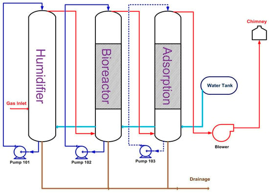
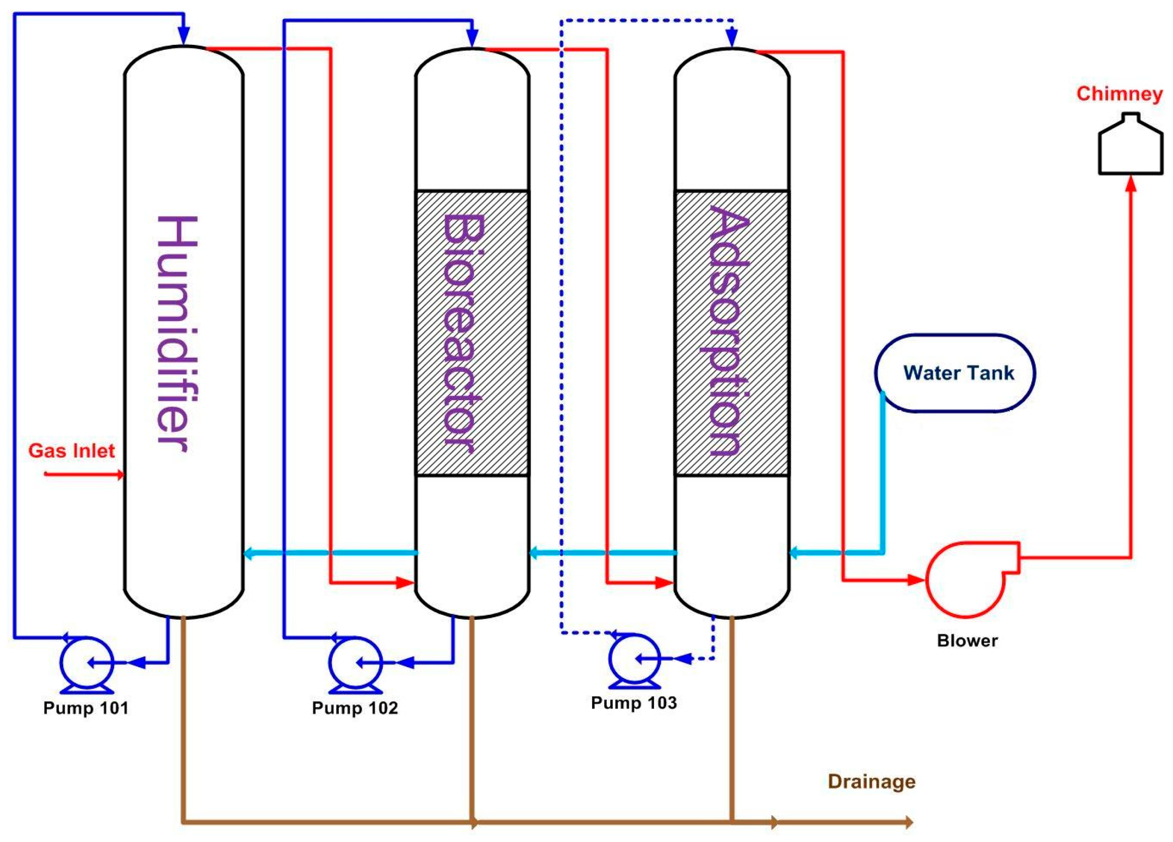
The pilot biofiltration system consisted of three main units: a humidifier, biofilter, and adsorption column. Figure 1 shows the process flow diagram of the system that was constructed and is located at a site near a wastewater pumping station.
Figure 1.
Process flow diagram of the in-built pilot biofilter system.
Humidification: The inlet air stream to the biofilter system is first humidified in a spray tower or humidifier. An important step in biofilter operation is to control the moisture levels in the incoming air as well as in the packing media. A dry biofilter medium leads to a reduction in microbial activity and subsequently poor treatment of waste gases. Low moisture levels can also cause both bed shrinkage and channeling effects. Often, reversing these effects is difficult without removing the bed material, which is costly. If the medium is too wet, problems such as development of anaerobic zones, clogging of pore spaces, leaching of nutrients, and increases in pressure drop may occur.
Three main factors that control moisture content in the biofilter medium are temperature, humidity, and residence time. Therefore, maintaining the moisture content at the optimum value warrants a humidification unit before the biofilter unit. Devinny et al. [12] report that if the inlet gas and the filter bed are at equilibrium with regard to moisture, neither evaporation nor condensation will occur; however, this is rarely the case, as microbial oxidation is an exothermic process that requires inclusion of a humidification unit. The role of this unit is also to maintain the temperature within a suitable range to sustain stable biofilter operation [12]. As shown in Figure 1, the water supply from the storage tank trickles against the airflow, and the water is dispersed in the form of uniform droplets that maximize the contact surface between the water and contaminated air. The humidified air is then passed to the biofiltration unit using a centrifugal blower.
Biofiltration: In the biofiltration process, contaminants from the airstream are removed by bio-oxidation in a biofilter, which is packed with media particles. In full-scale units, air distribution systems consisting of perforated pipes are designed to provide an equal airflow distribution across the packing media. Kumar et al. [13] report that the mechanism of biofiltration includes removing hazardous waste gases from the contaminated airstream by either absorption into the liquid phase, adsorption onto the porous media, and finally oxidation by the micro-organisms. The biofilter unit constructed in this study consists of the manufactured AAC-based medium, which is described in detail in the subsequent section. In the biofiltration unit, the concentrations of pollutants are reduced significantly by the bio-oxidation process, and the effluent stream from the biofilter is directed to the adsorption column.
Adsorption: The adsorption unit is packed with activated carbon. This process is considered a polishing step that is required to ensure no trace pollutants escape to the surrounding atmosphere. In general, adsorption occurs on either fixed or fluidized bed adsorbents such as activated carbon or zeolite. This process is the most efficient for treating pollutants at low concentration levels. However, it should be noted that adsorption is simply the transfer of pollutants from the gas phase to the solid phase (i.e., not elimination of pollutants). Devinny et al. [12] report that different factors such as the types of pollutants, concentration levels, flow rate, and temperature control the effectiveness of adsorption. Once the adsorbents reach the adsorptive capacity, they need to be removed and treated as hazardous solid waste. Adsorbents can be regenerated by recovering pollutants by desorption with either steam or hot air [12].
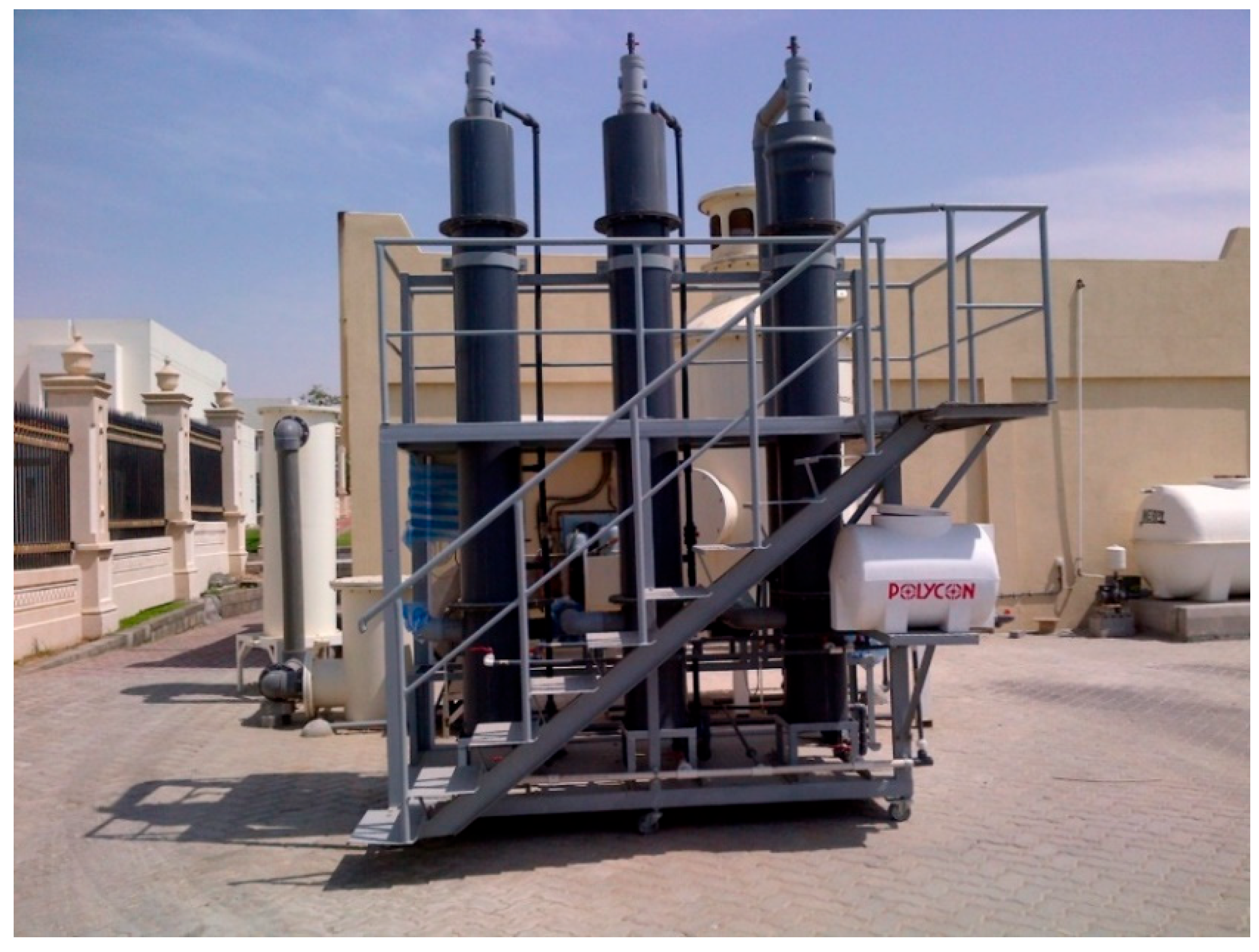
Three important parameters, namely breakthrough capacity, saturation capacity, and working capacity, are used to illustrate the adsorber capacity. Here, breakthrough capacity is defined as the capacity of the bed at the time where un-adsorbed contaminant begins to be released. Saturation capacity is defined as the maximum amount of pollutants that can be adsorbed per unit weight of carbon. Working capacity is defined as a fraction of the saturation capacity. The pilot biofilter system constructed based on the above flow diagram (Figure 1) using Polyvinyl Chloride (PVC) is shown in Figure 2. The column dimensions are as follows: internal diameter = 0.29 m, packing height = 1.85 m, total height = 2.91 m, and packing volume = 0.122 m3. For an airflow rate of 0.013335 m3/s, this gives an EBRT of 9.15 s.
Figure 2.
In-built pilot biofilter system.
2.2. Manufacturing Autoclaved Aerated Concrete (AAC) Biofilter Media
Selecting the biofilter media is critical in the design and performance of biofiltration processes. Micro-organisms present in the media biologically oxidize harmful VOCs and odorous compounds. Nicoli and Janni [14] report that packing media material directly influences the overall removal efficiency of the process [14]. When selecting biofilter media, a number of factors including microbial growth conditions, porosity of the media, durability, moisture holding capacity, nutrient content, and pressure drop are considered. Different materials such as wood chips [14], a wood chip–rice husk mixture [5], and a wood chip–mushroom compost mixture [15] have been used as biofilter media. Removal efficiencies vary between 90 and 99% when odorous compounds such as H2S, TEA (triethylamine), and ammonia [5,14,15] are treated at varying EBRTs.
In our study, the materials required for preparing biofilter media include AAC 86%, activated carbon 7%, cement 0.06%, peat 6.5%, and fertilizer 0.1% by weight. AAC is porous and has a high compressive strength and large surface area that help withstand the pressure drop and promote bacterial growth conditions, respectively. It is also inexpensive and abundant at construction waste sites. Activated carbon is an adsorbent that can modulate concentration variations under dynamic conditions and help provide stability. Cement is used as a coating agent. The biofilter operation mechanism depends heavily on the micro-organisms; peat is an organic material that has plenty of micro-organisms and organic nutrients. Fertilizer is a nutrient that provides the nitrogen, phosphorus, and potassium needed for biomass growth.
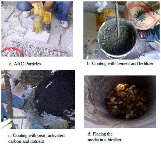
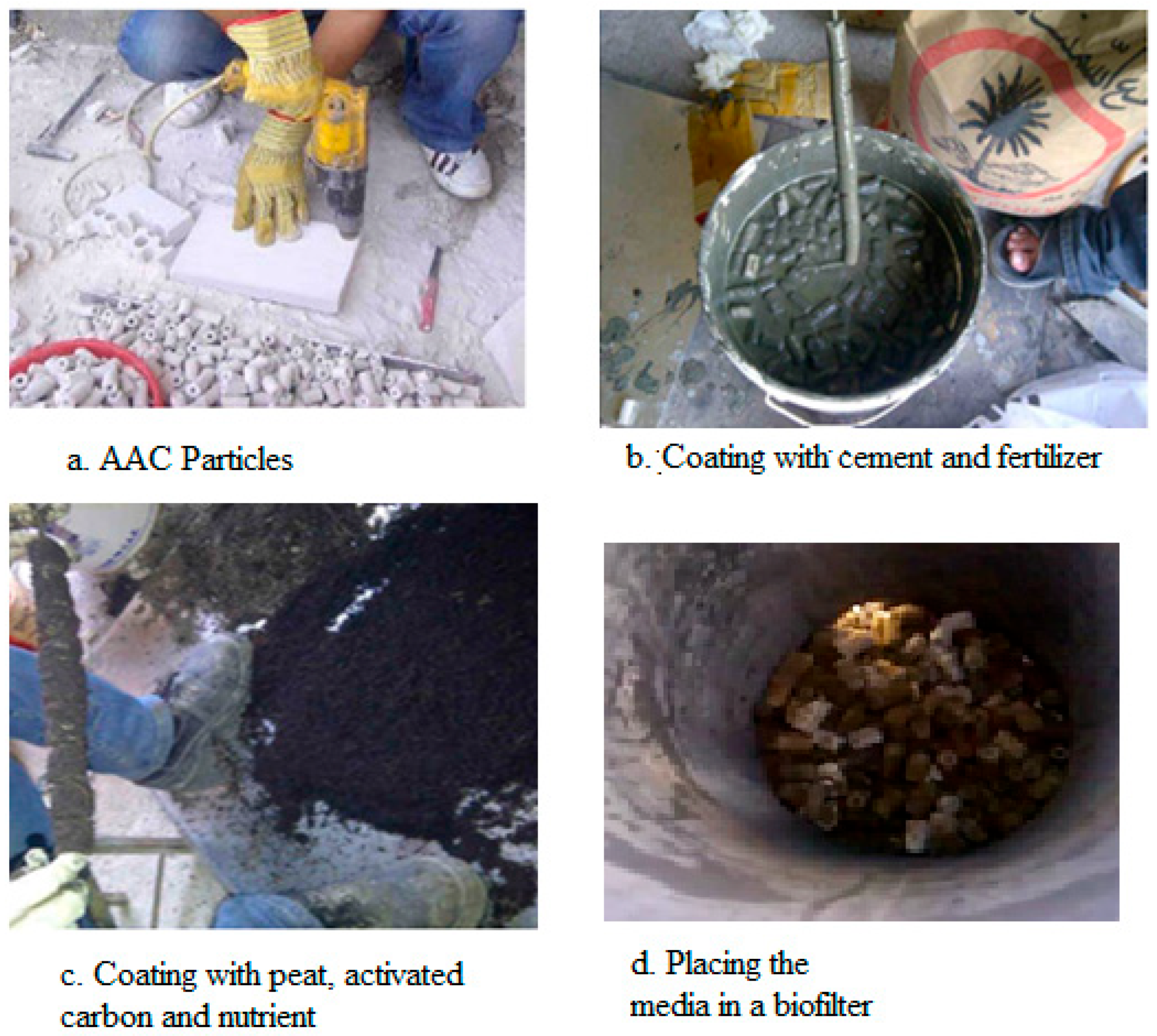
For preparing the biofilter media, AAC blocks were first drilled to make hollow cylindrical-shaped particles (Figure 3a) of approximately 2.0–2.5 cm in length and 1.5 cm in outside diameter. Subsequently, AAC particles were soaked in water for two consecutive days. The hollow structure allows higher surface areas for biomass growth both inside and outside the surfaces of the particles. The cement, fertilizer, and required amount of water were added to the AAC particles. Before mixing, fertilizer and peat were sieved using a 0.5 mm sieve tray, and the activated carbon was sieved using a 0.6 mm sieve tray. The resulting content was mixed homogeneously until the AAC particles were completely coated with the cement mixture (Figure 3b). Following this step, AAC particles were coated with a mixture of peat and activated carbon (Figure 3c). After the media particles were completely dried for two days, they were randomly packed manually in the biofilter column (Figure 3d). The internal porosity of AAC and the estimated bed void fraction were about 75% and 40%%, respectively. Empty spaces of 10 cm were kept in the upper and lower sections of the biofilter unit.
Figure 3.
AAC biofilter packing media manufacturing stages.
As the last step, the adsorption unit (i.e., polishing unit) was prepared by adding a thin layer of AAC media on a support tray followed by adding activated carbon above. For a basis of 250 g particles, the composition is distributed as follows: AAC 86.34% (215.85 g), activated carbon 7% (17.59 g), peat 6.5% (16.25 g), fertilizer 0.1% (0.25 g), and cement 0.06% (0.15 g).
3. Results and Discussion
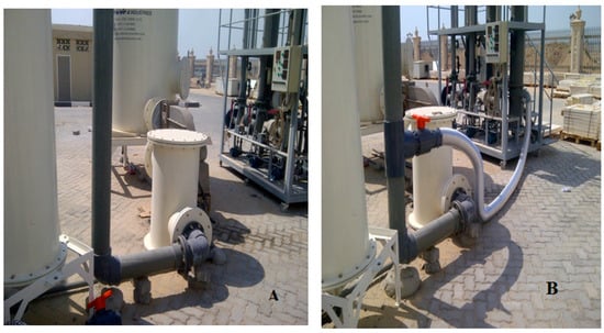
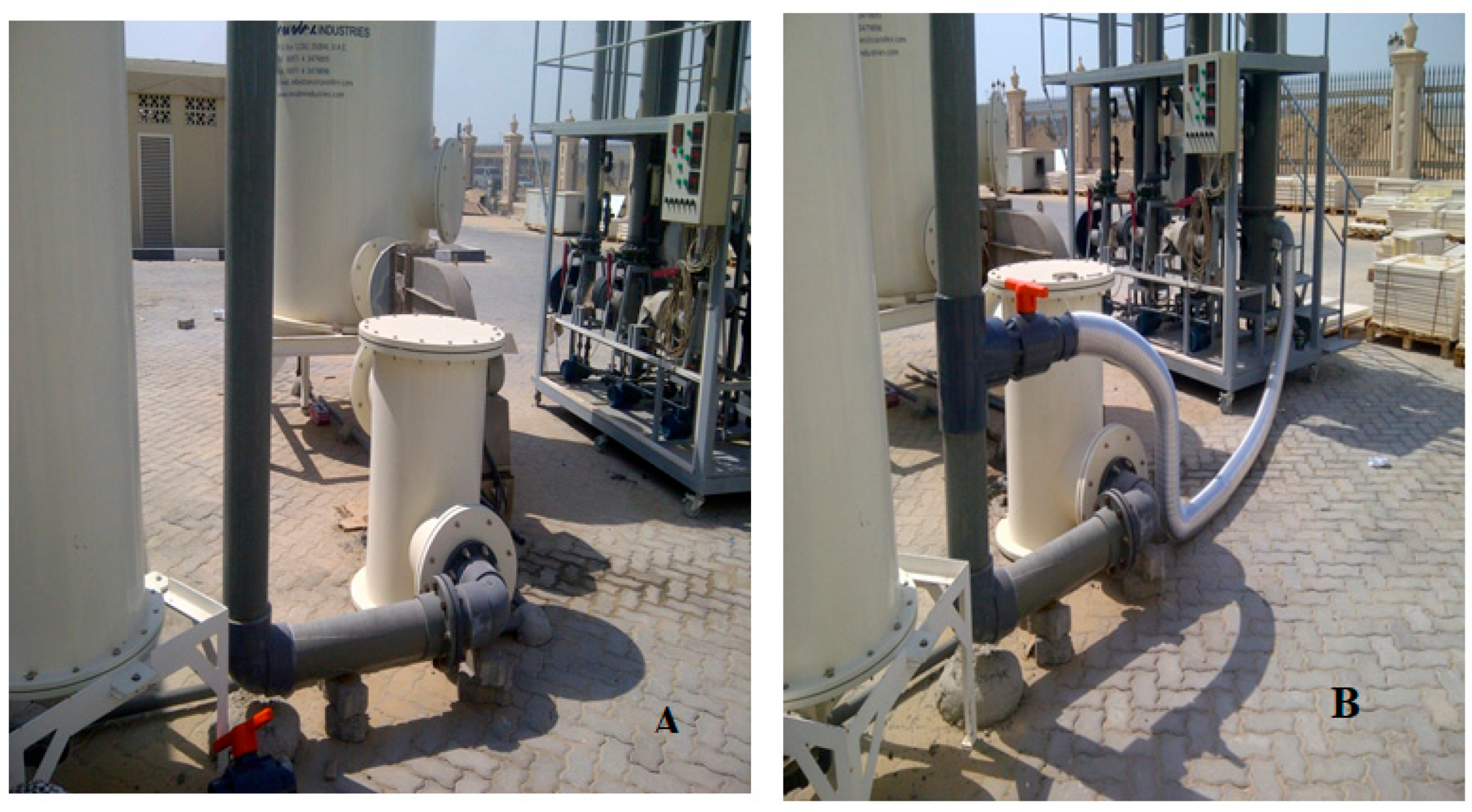
In order to evaluate the performance of AAC media in H2S removal, the pilot biofilter system was connected to an outlet air stream of a wastewater pumping station. The airstream loaded with H2S from the pumping station was previously treated in a commercial carbon adsorber installed at the site of the wastewater pumping station. In order to test AAC-based biofilter media, we diverted part of the polluted air to the pilot biofilter system that was built in our study. Figure 4 shows that part of the airstream from the pumping station is diverted from the existing adsorber unit (Figure 4A) to the in-built biofilter system shown (Figure 4B). The semi-rigid flexible aluminum hose was used for the connection due to its simplicity. Sampling ports were made on the aluminum hose to measure H2S concentrations, and the airflow rate was controlled using blowers, a damper, and a ball valve. The PVC ball valve supports high pressure and temperature conditions, and it is widely used under corrosive conditions (i.e., presence of H2S). Air and water leak tests were performed before starting the experiments. This was done by allowing air and water to pass through all pipe joints, connections, and columns separately, so that any leakage could be traced. Since air leakage might not be visible, soap foam was used on pipe joints in order to make sure any air leaks were noticeable before actual experiments were carried out.
Figure 4.
A portion of pumping station air is diverted from the existing commercial adsorption unit (A) to the in-built pilot biofilter system (B) for testing.
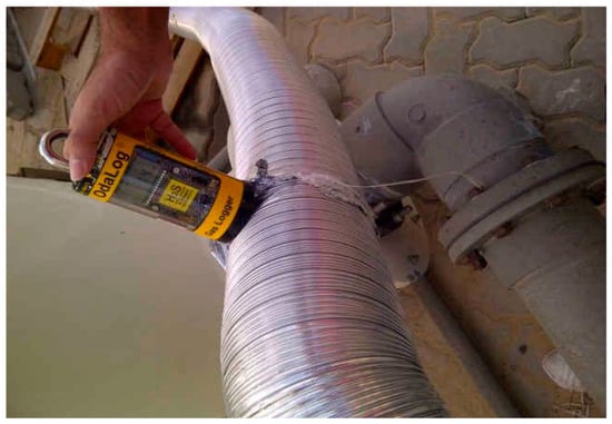
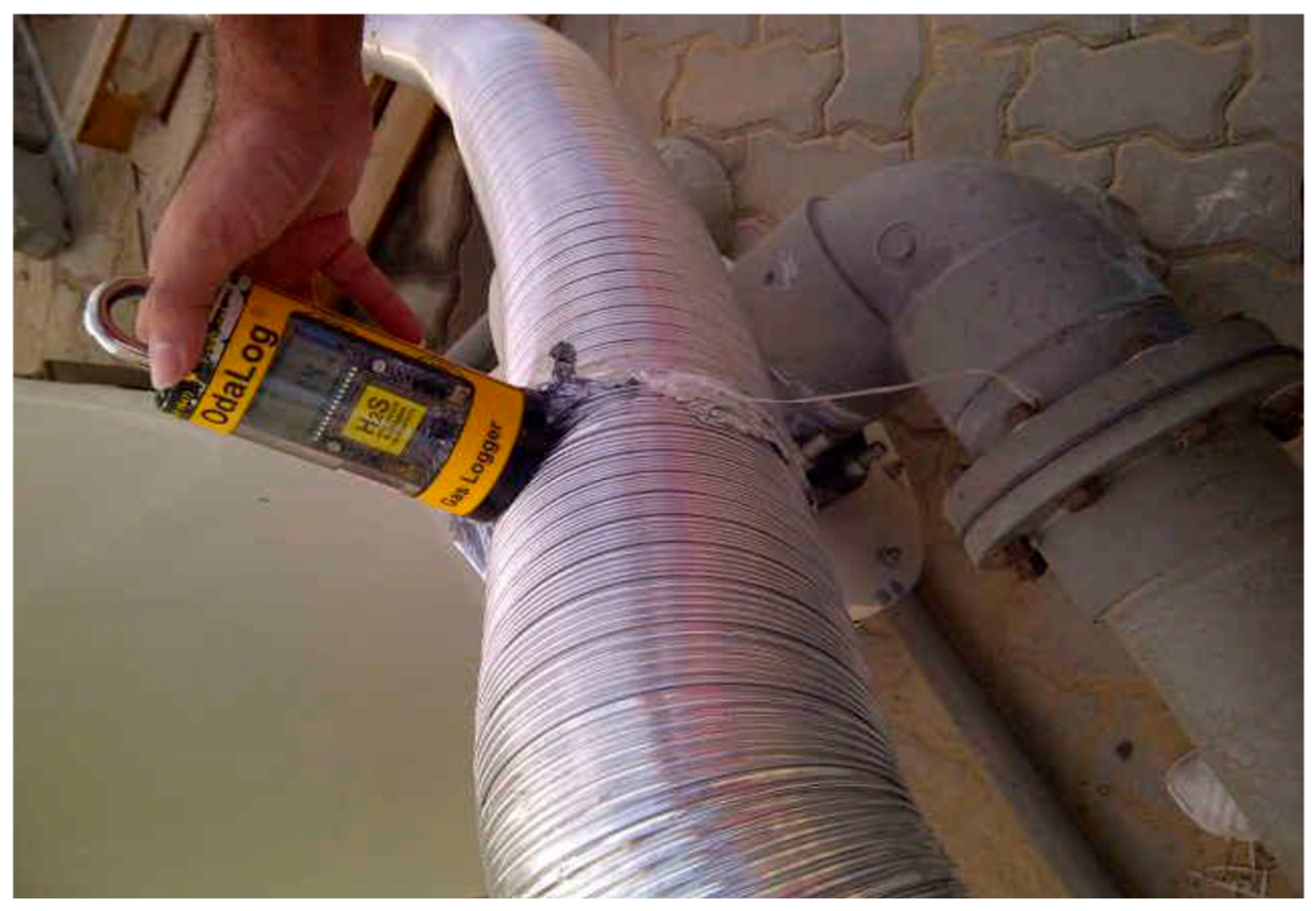
Hydrogen sulfide (H2S) concentrations were measured using OdaLog L2 (H2S Gas Logger) [16], which can measure H2S concentrations with ±0.1 accuracy for a concentration range of 0–200 ppm. OdaLog L2 is a popular instrument for monitoring H2S emissions at both pump and lift stations, collection systems, and receiving manholes [16]. Tedlar bags were also used to collect air samples [17]. A Tedlar bag is kept in a leak-free box that is connected to a pump. A sampling tube is connected to the bag from one side and to the sampling source from the other end. A pump is used to create a vacuum in the sampling box, which causes the air sample to be collected in the Tedlar bag. Experiments were conducted over a period of five months, and H2S concentration measurements were taken at the inlet to the biofilter system and the outlets of the humidifier, biofilter column, and adsorption column. During the period of operation, the average temperature and relative humidity at the inlet to the pilot unit were 29 °C and 67%, respectively. Figure 5 illustrates taking a sample from the inlet duct of the pilot biofilter system.
Figure 5.
H2S concentration measurement using OdaLog Gas Logger at the inlet duct to the pilot biofilter.
Biofilter performance is evaluated using several important parameters, such as the empty bed residence time (EBRT). It is defined as the bed filter volume divided by the air flow rate [10]:
where EBRT is the empty bed residence time (seconds); V is the filter bed volume (m3); and Q is the airflow rate (m3 s−1). The required EBRT for efficient removal of pollutants depends highly on the type of odorous or VOC compound being removed, as well as the type of biofilter media used. Generally, the EBRT overestimates the real treatment time. The actual residence time is defined as the total bed volume multiplied by the porosity of the filter media, divided by the airflow rate [10].
where τ is the true residence time (seconds) and θ is porosity. In general, τ < EBRT. Either EBRT or τ can be used to describe the performance of a biofilter. Very low EBRT represents superior biofilter performance. EBRT or τ can be altered by changing the volumetric flow rate of air or the packing media volume. Other biofilter performance parameters include removal efficiency (RE%), mass loading rate (g·m−3·s−1), and elimination capacity, which is also known as removal rate.
Removal efficiency (RE%) is defined as
where Cgi and Cgo (g·m−3) are the inlet and outlet concentrations of pollutants to the biofilter, respectively. Mass loading rate is defined as the mass of the contaminant to the biofilter per volume of filter material per unit time (g·m−3·s−1).
Elimination capacity, also known as removal rate, is defined as the mass of contaminants removed per volume of filter material per unit time (g·m−3·s−1).
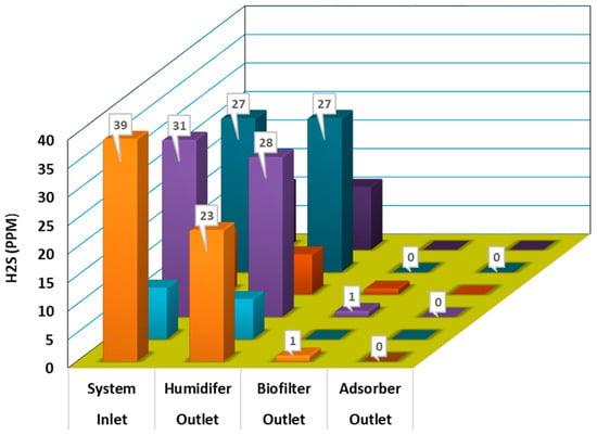
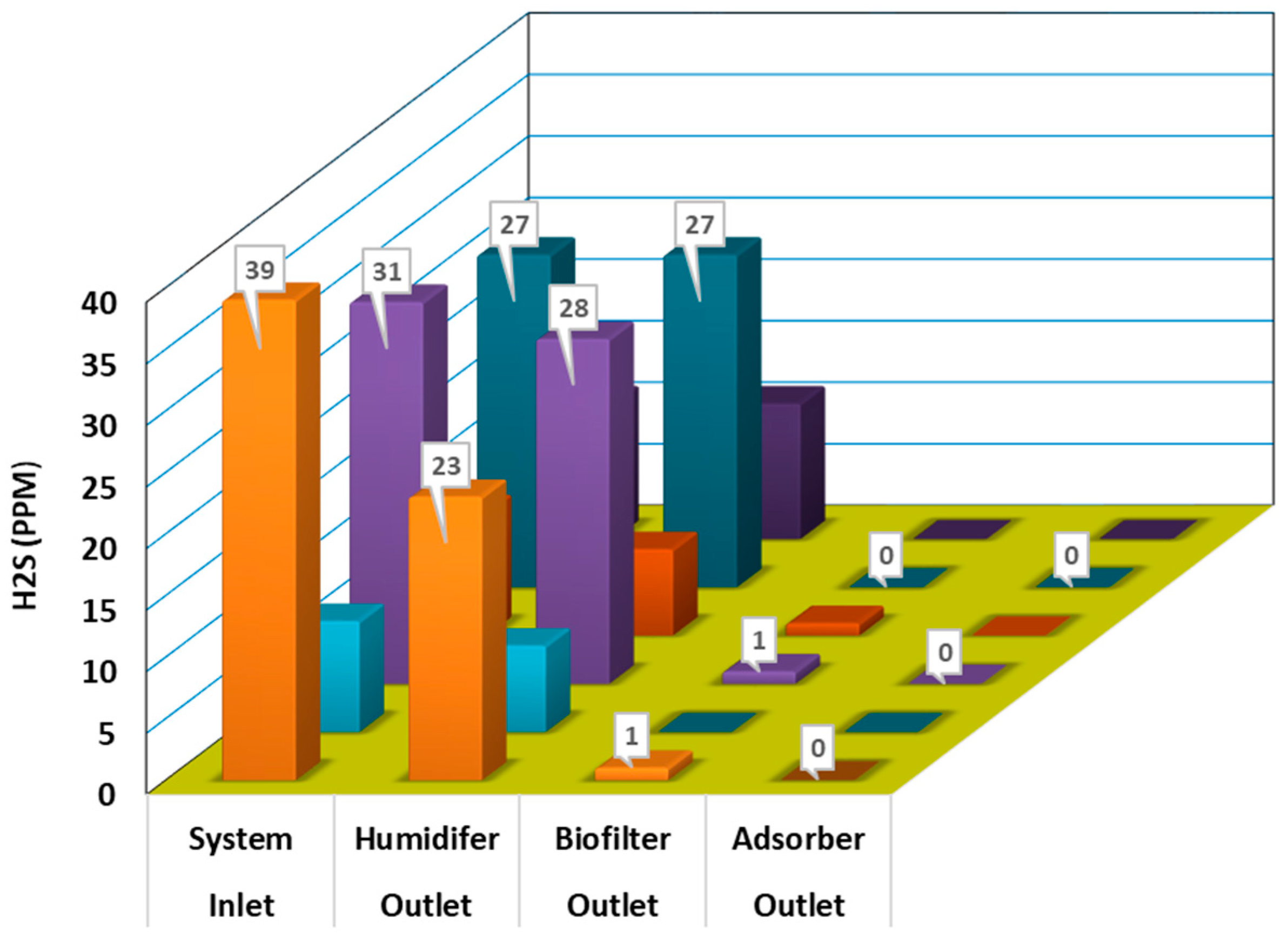
Figure 6 shows typical steady-state data collected from the inlet to the pilot biofilter system and outlets of the humidifier, biofilter column, and adsorption unit. It demonstrates that the biofilter eliminates H2S from the airstream even before it is sent to the polishing unit, namely the adsorber.
Figure 6.
Typical H2S (ppm) concentration data from the inlet to the pilot biofilter system, and outlets of the humidifier, biofilter, and adsorber.
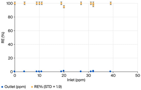
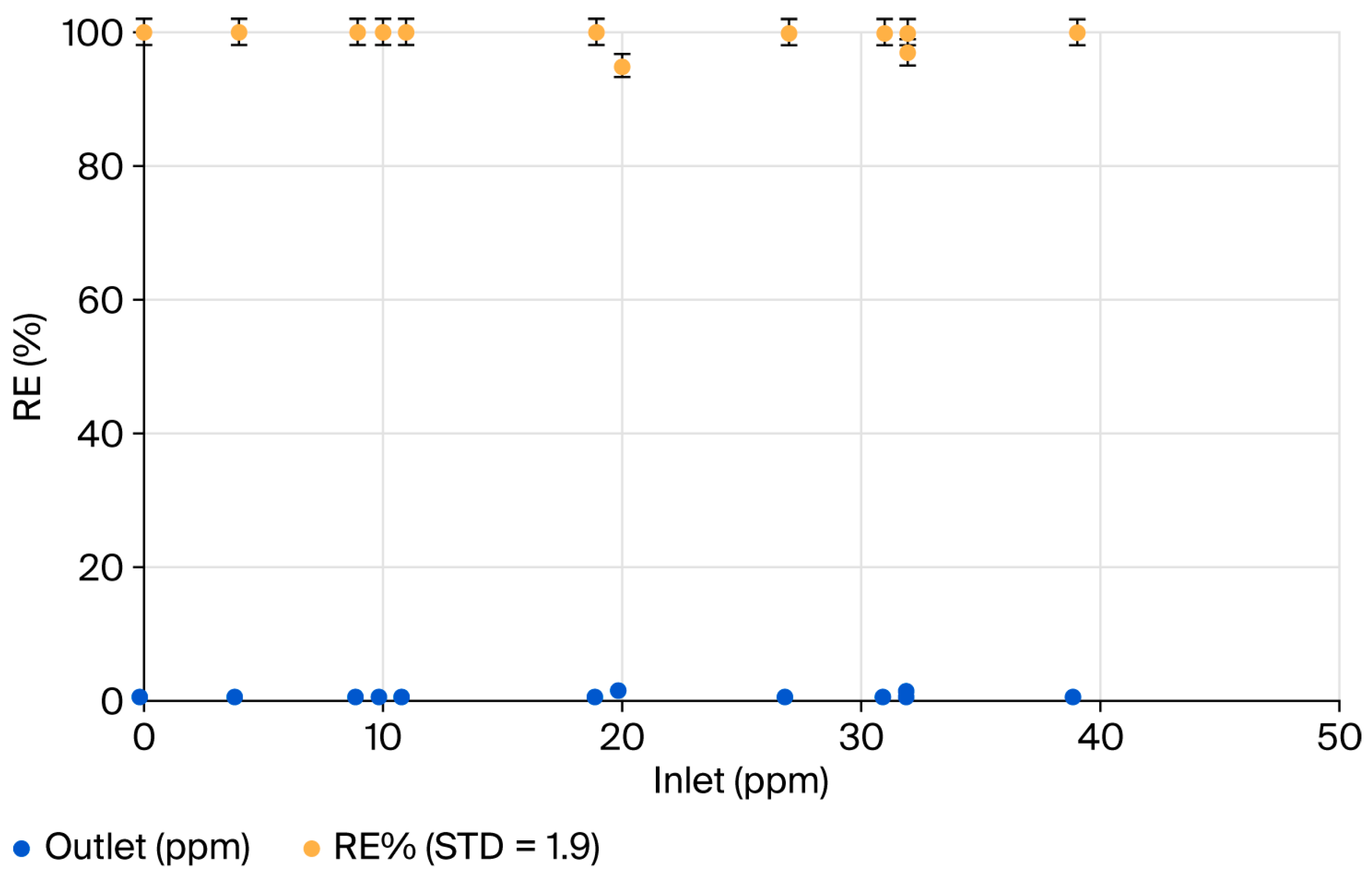
Figure 7 shows RE (%) as a function of inlet concentration, which varied over the period of testing from 4 to 39 ppm of H2S. The average inlet concentration was 21.2 ± 0.1 ppm of H2S. During the tests, EBRT also varied from 3.4 to 9.2 s due to fluctuations in the airflow rates. The average EBRT was 5.5 s. Since we use field data from a pumping station, the range of concentrations evaluated is relatively narrow. This concentration range could not be changed in practice (i.e., field conditions at the pumping station); however, in future, lab-scale experiments could be performed with a higher concentration range that can further strengthen and validate AAC media performance.
Figure 7.
Removal efficiency (%) (with STD = 1.9 for RE%, mean RE = 98.9%, data points = 12) as a function of inlet concentration of H2S (ppm) (mean = 21.2 ppm) to the pilot biofilter system.
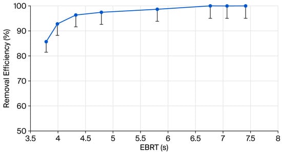
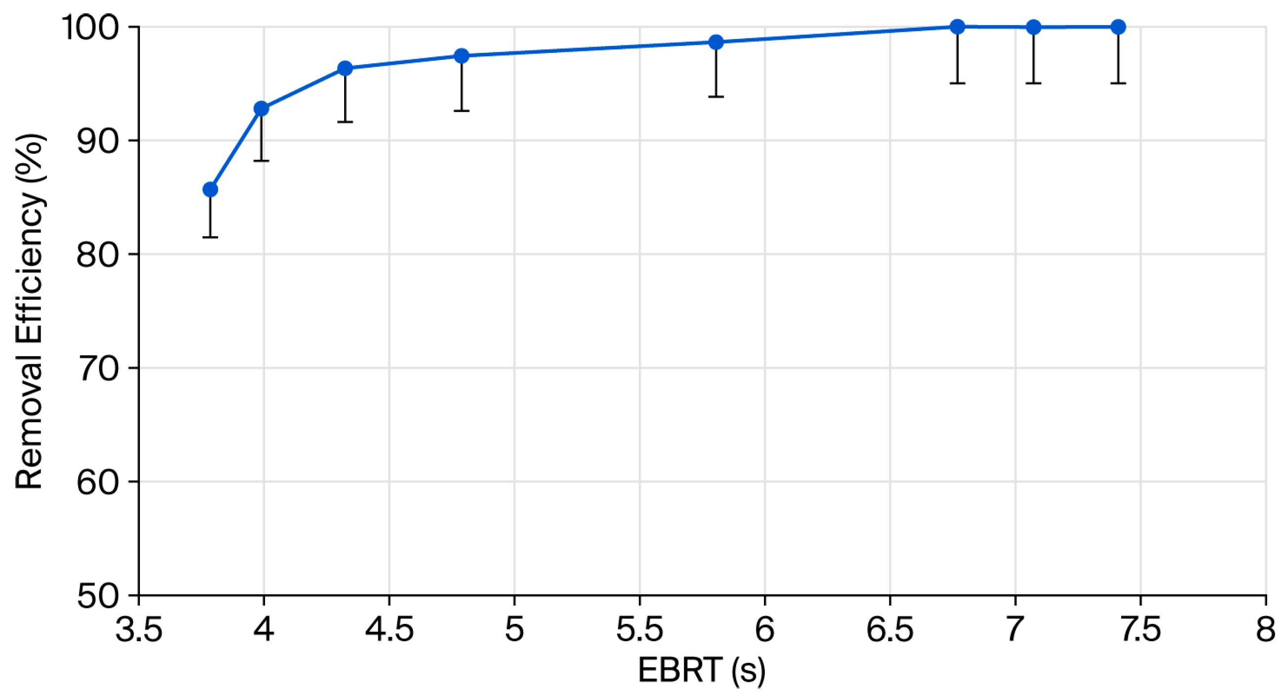
For the same experimental conditions, RE (%) as a function of EBRT is plotted in Figure 8, which shows the influence of EBRT on the removal efficiency. The mean RE% was 96.4% for eight experimental points with an SD of 5.0. Since the pilot biofilter system needs to be allowed to reach steady-state for several days, over a five-month period, we could only obtain eight data points for EBRT. For the same experimental conditions, the mean EBRT was 5.5 s with an SD of 1.5 s. We compared AAC-based biofilter media with the literature data. As shown in Table 2, this novel AAC-based biofilter media removes H2S at a low EBRT of 5.5 s with an RE% range of 95–100% for the concentration levels tested. The low EBRT implies better performance of AAC media for the concentration range (4–39 ppm) tested. Thus, when the concentration exceeds this range, the EBRT required will be higher than 5.5 s. For comparison, a commercial synthetic medium reported in the literature [18] requires at least an EBRT of 20 and 30 s to remove 12 and 40 ppm of H2S, respectively. Vikrant et al. [19] provide more details of H2S biofiltration studies as presented in Table 2. It should be noted that Kafle et al. [6] report an EBRT range of 1.6–3.1 s, which appears to be unusual for wood-based media. For example, Zhang et al. [7] and Aita et al. [20] report much higher EBRT values for wood-based media (i.e., a mixture of bark, wood bark, etc.).
Figure 8.
Removal efficiency (%) (with STD = 5.0 for RE%, mean RE = 96.4%, data points = 8) as a function of EBRT (s) (SD = 1.5 s for EBRT, mean = 5.5 s) to the pilot biofilter system.
Table 2.
Comparison of AAC-based media (last row) with the literature data.
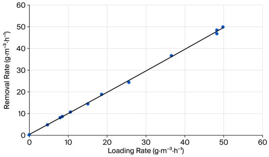
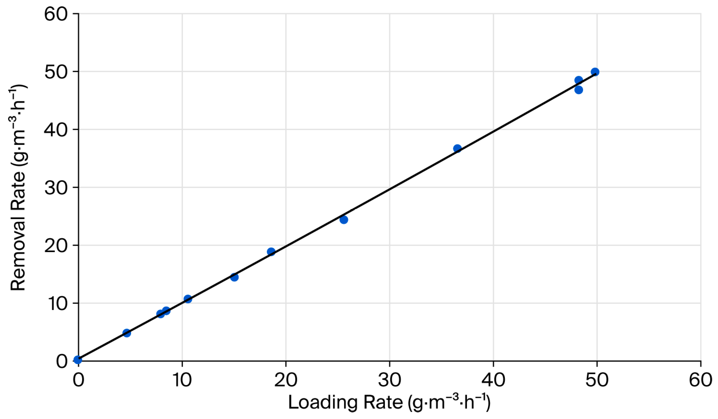
Figure 9 shows the removal rate or elimination capacity of H2S as a function of loading rate, which varied from 4.7 to 50 g·m−3·h−1. The average loading rate was 23.7 g·m−3·h−1. Since the RE% ranged from 95 to 100%, the removal rate, or elimination capacity, is almost the same as the loading rate, with an average of 23.4 g·m−3·h−1. Further, Figure 9 shows that the maximum elimination capacity is not reached, implying that the AAC elimination capacity can exceed 23.4 g·m−3·h−1. AAC-based biofilter media elimination is compared with other media. For removing H2S as a sole compound in the airstream and expanded schist as packing media, Shareefdeen [26] and Courtois et al. [27] report maximum elimination capacities of 30.0 and 36.4 g·m−3·h−1, respectively. For removing H2S in a mixture containing CO2 and CH4 and expanded schist as packing media, Jaber et al. [4] report a maximum elimination capacity of 25.2 g·m−3·h−1. Thus, the AAC-based media elimination capacity in our study is comparable to expanded schist media. Further testing in lab- or pilot-scale experiments is necessary to establish the maximum elimination capacity of AAC-based biofilter media.
Figure 9.
Removal rate of H2S as a function of loading rate.
4. Conclusions
In this work, a new biofilter medium using Autoclaved Aerated Concrete (AAC) has been developed and tested in an in-built pilot biofilter system. This system was installed at a wastewater pumping station which emits varying concentration levels (4–39 ± 0.1 ppm) of H2S. This work demonstrates that AAC biofilter media can successfully remove H2S at an average EBRT of only 5.5 s with a removal efficiency (RE%) range of 95–100% for an average inlet concentration of 21.2 ± 0.1 ppm of H2S. As compared to the literature data and based on the experiments performed over a 5-month period, AAC-based biofilter media give better removal performance in terms of EBRTs. However, it should be noted that the results presented in this paper are limited to the H2S concentration levels tested. A shorter EBRT of AAC media means that biofilters can be built with lower capital costs due to the substantial decrease in the biofilter size. In addition, the maximum elimination capacity of AAC can exceed 23.4 g·m−3·h−1. This work meets the SDG and creates a positive environmental impact because AAC waste that could end up in landfill is used to create a value-added product, namely a novel AAC-based biofilter medium. The AAC media developed in this study have regeneration potential and can be reused by adding the required nutrients. In the future, AAC media warrant further research to determine the maximum elimination capacity of AAC for H2S removal and the limitations on the removal performance of other odorous and hazardous VOCs of industrial interest. Physicochemical characterization and further lab-scale experiments can provide more insights into this novel AAC-based biofilter medium.
Author Contributions
Z.S.: concept, project management, literature, experiments, data collection, data analysis, and writing of the manuscript. A.A.: project management, supervision of AAC media manufacturing, pilot plant construction, and data collection. All authors have read and agreed to the published version of the manuscript.
Funding
This research received no external funding.
Data Availability Statement
Data available on reasonable request.
Acknowledgments
We acknowledge Beeah Group, Sharjah, UAE, for providing limited initial funding and helping undergraduate students Ali Ataya, Fatima Aqrabi, Hadiseh Hossein Pour, Mirette Guirgues, Saquib Ahmad, and Zafar Abbas.
Conflicts of Interest
The authors declare no conflicts of interest.
References
- Mohammadi, K.; Vaiškūnaitė, R.; Zigmontienė, A. Efficiency of Hydrogen Sulfide Removal from Biogas Using a Laboratory-Scale Biofilter Packed with Biochar, Cellular Concrete Waste, or Polyurethane Foam: A COMSOL Simulation Study. Processes 2025, 13, 329. [Google Scholar] [CrossRef] [Scilit]
- Zarei, M.; Bayati, M.R.; Ebrahimi-Nik, M.; Rohani, A.; Hejazi, B. Modelling the removal efficiency of hydrogen sulfide from biogas in a biofilter using multiple linear regression and support vector machines. J. Clean. Prod. 2023, 404, 36965. [Google Scholar] [CrossRef] [Scilit]
- Choi, J.H.; Kim, Y.H.; Joo, D.J.; Choi, S.J.; Ha, T.W.; Lee, D.H.; Park, I.H.; Jeong, Y.S. Removal of Ammonia by Biofilters: A Study with Flow-Modified Systems and Kinetics. J. Air Waste Manag. Assoc. 2003, 53, 92–101. [Google Scholar] [CrossRef] [Scilit] [PubMed]
- Mustafa, B.; Shareefdeen, Z. Recent developments in Artificial Neural Network (ANN), steady-state and transient modeling of gas-phase biofiltration process. South Afr. J. Chem. Eng. 2024, 49, 223–232. [Google Scholar] [CrossRef] [Scilit]
- Shareefdeen, Z. Chapter 6-High-Performance Biofilters for Air Treatment Applications. In From Biofiltration to Promising Options in Gaseous Fluxes Biotreatment; Gabriela, S., Éric, D., Eds.; Elsevier: Amsterdam, The Netherlands, 2020; pp. 111–127. [Google Scholar] [CrossRef] [Scilit]
- Rahman, R.; Fazlizan, A.; Asim, N.; Thongtha, A. Utilization of waste material for aerated autoclaved concrete production: A preliminary review. IOP Conf. Ser. Earth Environ. Sci. 2020, 463, 012035. [Google Scholar] [CrossRef] [Scilit]
- Devinny, J.S.; Deshusses, M.A.; Webster, T.S. Biofiltration for Air Pollution Control; CRC press LLC: Boca Raton, FL, USA, 1999. [Google Scholar] [CrossRef] [Scilit]
- Kumar, K.V.; Sridevi, V.; Harsha, N.; Chandana, M.; Rani, K.; Tech, M. Biofiltration and its application in treatment of air and water pollutants-A review. Int. J. Appl. OR Innov. Eng. Manag. 2013, 2, 226–231. [Google Scholar]
- Nicoli, R.E.; Janni, K.A. Biofilter media mixture ratio of wood chips and compost treating swine odour. Water Sci. Technol. 2001, 44, 261–267. [Google Scholar] [CrossRef] [Scilit]
- Gandu, B.; Sandya, K.; Rao, A.G.; Swamy, Y.V. Removal of air containing tri ethyl amine (tea) using vapor phase biofilter packed with wood chips and rice husk. Int. J. Ind. Eng. Manag. Sci. 2012, 2, 17–20. [Google Scholar] [CrossRef] [Scilit]
- Deshusses, M.A.; Johnson, C.T. Development and validation of a simple protocol to rapidly determine the performance of biofilters for VOC treatment. Environ. Sci. Technol. 2000, 34, 461–467. [Google Scholar] [CrossRef] [Scilit]
- Detection Instruments, OdaLog L2 Hydrogen Sulfide Gas Logger|Detection Instruments. Available online: https://detectioninstruments.com/odalog-l2-hydrogen-sulfide-gas-logger/ (accessed on 3 October 2025).
- PVDF (Tedlar®, Kynar®, & Solef®) PVDF (Tedlar® & Kynar®) Bag Sampling Solutions. Available online: https://www.keikaventures.com/s_tedlar.php (accessed on 3 October 2025).
- Zhang, C.; Li, B.F.; Jiang, Y.H. Full-Scale Study to Treat Hydrogen Sulfide with Biofilter. Appl. Mech. Mater. 2013, 443, 629–633. [Google Scholar] [CrossRef] [Scilit]
- Rabbani, K.; Charles, W.; Kayaalp, A.; Cord-Ruwisch, R.; Ho, G. Pilot-scale biofilter for the simultaneous removal of hydrogen sulphide and ammonia at a wastewater treatment plant. Biochem. Eng. J. 2016, 107, 1–10. [Google Scholar] [CrossRef] [Scilit]
- Kafle, G.K.; Chen, L.; Neibling, H.; He, B.B. Field evaluation of wood bark-based down-flow biofilters for mitigation of odor, ammonia, and hydrogen sulfide emissions from confined swine nursery barns. J. Environ. Manag. 2015, 147, 164–174. [Google Scholar] [CrossRef] [Scilit] [PubMed]
- Jaber, M.B.; Anet, B.; Amrane, A.; Couriol, C.; Lendormi, T.; Le Cloirec, P.; Cogny, G.; Fillières, R. Impact of nutrients supply and pH changes on the elimination of hydrogen sulfide, dimethyl disulfide and ethanethiol by biofiltration. Chem. Eng. J. 2014, 258, 420–426. [Google Scholar] [CrossRef] [Scilit]
- Hou, J.; Li, M.; Xia, T.; Hao, Y.; Ding, J.; Liu, D.; Xi, B.; Liu, H. Simultaneous removal of ammonia and hydrogen sulfide gases using biofilter media from the bio dehydration stage and curing stage of composting. Environ. Sci. Pollut. Res. 2016, 23, 20628–20636. [Google Scholar] [CrossRef] [Scilit] [PubMed]
- Jaber, M.B.; Couvert, A.; Amrane, A.; Rouxel, F.; Le Cloirec, P.; Dumont, E. Biofiltration of high concentration of H2S in waste air under extreme acidic conditions. New Biotechnol. 2016, 33, 136–143. [Google Scholar] [CrossRef] [Scilit] [PubMed]
- Jaber, M.B.; Couvert, A.; Amrane, A.; Le Cloirec, P.; Dumont, E. Removal of hydrogen sulfide in air using cellular concrete waste: Biotic and abiotic filtrations. Chem. Eng. J. 2017, 319, 268–278. [Google Scholar] [CrossRef] [Scilit]
- Jaber, M.B.; Couvert, A.; Amrane, A.; Rouxel, F.; Le Cloirec, P.; Dumont, E. Biofiltration of H2S in air—Experimental comparisons of original packing materials and modeling. Biochem. Eng. J. 2016, 112, 153–160. [Google Scholar] [CrossRef] [Scilit]
- Aita, B.C.; Mayer, F.D.; Muratt, D.T.; Brondani, M.; Pujol, S.B.; Denardi, L.B.; Hoffmann, R.; da Silveira, D.D. Biofiltration of H2S -rich biogas using Acidithiobacillus thiooxidans. Clean Technol. Environ. Policy 2016, 18, 689–703. [Google Scholar] [CrossRef] [Scilit]
- Shareefdeen, Z. Hydrogen sulfide (H2S) removal using schist packings in industrial biofilter applications. Korean J. Chem. Eng. 2015, 32, 15–19. [Google Scholar] [CrossRef] [Scilit]
- Courtois, A.; Andrès, Y.; Dumon, É. H2S biofiltration using expanded schist as packing material: Influence of packed bed configurations at constant EBRT. J. Chem. Technol. Biotechnol. 2015, 90, 50–56. [Google Scholar] [CrossRef] [Scilit]
- Jaber, M.B.; Couvert, A.; Amrane, A.; Le Cloirec, P.; Dumont, E. Hydrogen sulfide removal from a biogas mimic by biofiltration under anoxic conditions. J. Environ. Chem. Eng. 2017, 5, 5617–5623. [Google Scholar] [CrossRef] [Scilit]
- Vikrant, K.; Kailasa, S.K.; Tsang, D.C.; Lee, S.S.; Kumar, P.; Giri, B.S.; Singh, R.S.; Kim, K.-H. Biofiltration of hydrogen sulfide: Trends and challenges. J. Clean. Prod. 2018, 187, 131–147. [Google Scholar] [CrossRef] [Scilit]
- Shareefdeen, Z.; Herner, B.; Webb, D.; Wilson, S. Hydrogen sulfide (H2S) removal in synthetic media biofilters. Environ. Prog. Sustain. Energy 2003, 22, 207–213. [Google Scholar] [CrossRef] [Scilit]



Disclaimer/Publisher’s Note: The statements, opinions and data contained in all publications are solely those of the individual author(s) and contributor(s) and not of MDPI and/or the editor(s). MDPI and/or the editor(s) disclaim responsibility for any injury to people or property resulting from any ideas, methods, instructions or products referred to in the content. |
© 2026 by the authors. Licensee MDPI, Basel, Switzerland. This article is an open access article distributed under the terms and conditions of the Creative Commons Attribution (CC BY) license.