


Abstract
Environmental concerns arising from the exploitation of fossil-based resources in electricity generation have emerged as a pressing global issue. In order to achieve the objective of net-zero emissions in this sector, it is imperative to undergo an ecological transition, in which renewable energy sources (RES), such as photovoltaic (PV) and wind energy, assume a central role. However, the deployment of RES also necessitates the parallel operation of Energy Storage Systems (ESS) to compensate for their intermittent characteristics, thereby ensuring the stability of the power network. In the context of large-scale power plants, the construction of conventional low-voltage (LV) battery racks does not appear to be the most technologically advanced approach. Using medium-voltage (MV) racks could enhance the system’s competitiveness in terms of energy efficiency and cost. As the conversion system is a significant contributor to the overall cost of the BESS, this study analyzes DC/AC converters in order to clarify this aspect. Firstly, a comparison of the conventional LV and the proposed MV converter is presented in terms of electrical performance. Subsequently, a Life Cycle Assessment (LCA) analysis is applied to the constitutive components of the converter in order to evaluate their environmental impact based on the same delivered power (15 MVA). The findings suggest that the proposed MV DC/AC converter, which embeds state-of-the-art 3.3 kV Silicon Carbide (SiC) power modules, exhibits enhanced efficiency and a reduction in environmental impact when compared to the LV converter.
1. Introduction
1.1. Renewable Energies and Power Electronics Trends
The combustion of conventional fossil-based resources in the production of electricity has become a matter of global significance due to the resulting environmental concerns. The objective of net-zero emission by 2050 is set to encourage a substantial ecological transition, with renewable energies such as photovoltaic (PV) and wind power being recognized as the principal drivers [1] of this energy revolution. While renewable energy sources have been found to be less controllable than traditional resources, large-scale deployment of renewables does require the parallel operation of a high-power Energy Storage System (ESS) to compensate for their intermittent characteristics, thus ensuring the stability of power networks [2]. Consequently, the ESS and renewable power plants have been progressively integrated into electricity grid mixes. As asserted by [1], the aggregate power generation is projected to reach approximately 2000 GW by the year 2050 for energy storage systems and 5000 GW for solar farms. Recent studies have indicated that low-voltage (LV) photovoltaic (PV) systems, particularly their power-electronics-based direct/alternating (DC/AC) current conversion stage, have experienced an increase in voltage, extending from 600 volts to 1500 volts on the DC side and from 300 volts to 800 volts on the AC side, respectively. This development has the potential to enhance the competitiveness of the overall system in terms of efficiency and cost effectiveness. The development of ESS is also subject to this tendency; battery racks are currently standardized to operate at 1500 V [3]. As power capacity tends to increase, it is to be expected that higher voltage levels are being investigated. This indicates that power converters in renewable energy plants and energy storage systems are increasingly being subjected to an upward trend in medium-voltage (MV) levels.
Contextually, the sustainability of novel electrical architectures should be assessed. Previous studies have investigated the environmental impact of power electronic converters using life cycle assessment (LCA) methodologies. These studies have highlighted the importance of semiconductor devices, passive components, and manufacturing processes in determining the overall environmental footprint of power electronic converters [4]. However, the existing studies have mainly focused on specific converter configurations, component-level improvements, or single technology assessments, while the environmental implications of the transition toward higher-voltage converter architectures remain insufficiently explored [5]. In parallel, silicon carbide (SiC) power devices have been extensively studied due to their superior electrical characteristics, including higher switching frequency capability, reduced switching and conduction losses, and improved efficiency in comparison with conventional silicon-based technologies [6]. However, it should be noted that the potential environmental benefits of SiC integration cannot be directly deduced from electrical performance improvements. These benefits also depend on semiconductor manufacturing processes, material requirements, and operating conditions over the converter lifetime [7]. Moreover, available research studies on MV power conversion systems for renewable energy applications have mainly addressed converter topologies, control strategies, and technical feasibility, whereas comprehensive comparisons between LV and MV ESS converters considering both electrical performance and life cycle environmental impacts remain limited [8]. Therefore, a system-level assessment combining electrical performance and life cycle environmental analysis is crucial to evaluate whether the transition toward MV ESS converters provides environmental advantages in addition to its expected technical benefits.
From this standpoint, the present study introduces a novel contribution to the existing literature by comparing LV and MV ESS DC/AC converters, with a focus on their electrical performance and environmental impact. The LV DC/AC converter is an exemplar case study, integrating classic Silicon Insulated Gate Bi-Polar Transistor (Si-IGBT) technology. In contrast, the MV model employs state-of-the-art 3.3 kV Silicon Carbide Metal-Oxide Field-Effect Transistor (SiC MOSFET) power modules.
1.2. Material and Resource Savings
The present article adopts the Life Cycle Assessment (LCA) methodology in order to evaluate the environmental impact of two different power electronics utility-scale technologies of energy storage systems (ESS), considering their manufacturing process.
LCA is a well-known, internationally standardized, and comprehensive methodology that quantifies the consumption of resources (i.e., raw materials, energy, waste, etc.) and related emissions all over the life cycle of a product or process.
Introduced since the 1980s in different research and industrial sectors, it has become an efficient eco-design tool for both for commercialized and new-generation products.
The methodology of LCA is defined in accordance with international standards [9,10] and is structured in four iterative steps, i.e.,:
- Goal and Scope definition sets up the parameters and approaches behind the assessment, including any aspect to be defined and clarified, such as: the objective of the study, the system boundary, the functional unit (metric of the study), assumptions and limitations;
- Life Cycle Inventory (LCI) involves the systematic collection and review of data on input and output flows (in terms of energy, materials, waste, etc.) involved in each stage of a product’s life cycle;
- Life Cycle Impact Assessment (LCIA) is a process that involves the calculation and evaluation of the potential environmental impacts arising from the LCI, directly on a dedicated LCA software;
- Interpretation of results is the conclusive step, supported by a hotspot analysis that enables lessons learnt to be disclosed to a public audience.
The present article includes the environmental comparative assessment of LV vs. MV power converters that have been dedicated to ESS through the means of LCA methodology, considering the same service delivered (15 MVA) for a fair comparison. The assessment adopts a “cradle-to-gate” perspective, focusing exclusively on the manufacturing stage of the converter systems. The installation, use, and end-of-life phases were not included in the system boundaries. Although differences in electrical efficiency may affect environmental impacts during operation, robust modelling of this use phase would require detailed information regarding operating profiles, utilization rates, electricity supply scenarios, maintenance activities, service lifetime, and component degradation. These aspects were not addressed in the present study, whose focus is purely on the material aspects regarding the compared electrical architectures. Consequently, the analysis was intentionally limited to the manufacturing stage in order to provide a transparent and consistent comparison of the environmental implications associated with the material composition and design of the low-voltage and medium-voltage converter architectures.
The various phases of the LCA methodology applied to the low-voltage and medium-voltage converter systems are outlined in the dedicated sections of the present article.
1.3. Structure of the Paper
The structure of the paper is outlined as follows: after the introduction in Section 1, Section 2 presents the two converter configurations and their main electrical characteristics and the methodology for calculating and sizing the relevant components, as well as providing a recap of the components considered and the modelling approach. Section 3 describes the methodology and scope of the comparative life cycle assessment (LCA), including the definition of the common functional unit, the corresponding bill of materials (BoM), and the life cycle inventory (LCI) for the two configurations. The comparison considers the same delivered service, corresponding to 15 MVA of power output. Section 4 presents the environmental impact assessment based on the LCA results. Finally, Section 5 concludes the paper by providing the study’s main outcomes and conclusions.
2. Comparison of the Bill of Materials for Low- and Medium-Voltage BESS Power Converters
2.1. Main Characteristics of Low- and Medium-Voltage BESS Power Converters
Table 1 summarizes the main characteristics of the two power conversion modules (PCMs) considered in this study: the 625 kVA low-voltage (LV) PCM, which is used as the reference case, and the advanced 1.5-MVA medium-voltage (MV) PCM.
Table 1.
Comparison of the main characteristics of the LV Si-IGBT-based reference converter and the advanced MV SiC-MOSFET-based BESS DC/AC converter.
The LV PCM is based on a T-type topology and relies exclusively on silicon IGBT power modules. The external switching devices are rated at 1.7 kV–800 A, while the internal devices, arranged in anti-series, are rated at 1.2 kV–600 A, and the PCM operates at a switching frequency of 2 kHz. The associated LCL filter is sized according to the operating conditions of the converter to ensure a total harmonic distortion (THD) of the current below 3%. The 625 kVA LV PCM is connected to a 480 V RMS, 50/60-Hz AC voltage, achieving a maximum efficiency of 98.9% and a minimum efficiency of 97.5%.
In contrast, the advanced MV PCM is rated at 1.5 MVA and is based on an active neutral point clamped (ANPC) topology. It combines 3.3 kV silicon carbide (SiC) MOSFETs for the external switching devices with 3.3 kV silicon insulated-gate bipolar transistors (IGBTs) for the internal devices. The external SiC MOSFETs operate at a switching frequency of 7 kHz, taking advantage of the high-frequency switching capability of SiC technology. In contrast, the internal silicon IGBTs are operated at the fundamental frequency of 50 Hz, exploiting their favorable conduction characteristics while limiting the impact of their unfavorable switching characteristics. The LCL filter is similarly sized to keep the current THD below 3%. The 1.5-MVA MV PCM is designed for a 2.1 kV RMS, 50-Hz AC voltage and achieves maximum efficiency of 99.6% and minimum efficiency of 99.2% [11]. Overall, the two PCMs differ in their voltage level, semiconductor technology, and rated power.
2.2. LCL Filter Design Methodology
The main electrical parameters and LCL filter design quantities were determined based on the rated operating conditions of each converter. First, the RMS and peak AC currents were calculated from the maximum apparent power and the corresponding line-to-line RMS voltage. The inverter-side current ripple was then defined as a fraction of the rated RMS current, after which the corresponding peak current, including the ripple contribution, was determined.
Next, the LCL filter was sized by selecting the inverter-side inductance based on the maximum current ripple and the converter’s switching frequency. The filter capacitance was then determined by limiting its reactive power to 5% of the converter’s rated apparent power. Finally, the grid-side inductance was calculated from the selected LCL resonant frequency. The resulting design parameters and the equations used to determine them are summarized in Table 2.
Table 2.
Calculation procedure and design equations used for the LCL-filter sizing.
A THD below 3% was adopted as a design target for the converter. This value is used here as a performance target for the LCL filter design and does not represent a general normative limit.
2.3. LV Si-IGBT Based DC/AC Converter (Reference Case)
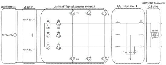
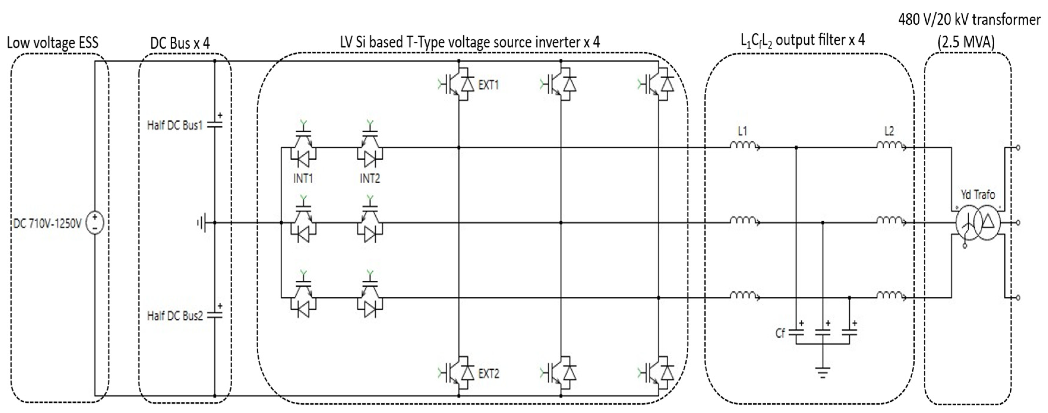
Each leg of the circuit is composed of four switches, and thus twelve switches are required to build the entire topology (Figure 1). A comparative analysis of power modules has been conducted, in which two distinct references were selected for analysis: 1.7 kV/800 A (IGBT 1) and 1.2 kV/600 A (IGBT 2) [16]. A study was conducted on the configuration of the capacitors with the objective of reducing the size of the converter. Consequently, a single DC-Bus consists of 30 capacitors, each with a capacity of 1500 µF (900 V/100 A) (see Table 5). The complete Power Conversion Unit (PCU) consists of four 625 kVA Power Converter Modules (PCMs). Each PCM includes a DC bus, a T-type inverter, and an output LCL filter. In this reference case, power injection is performed at the 480 V low-voltage level.
Figure 1.
2.5 MVA low-voltage T-Type DC/AC low-voltage PCU composed of four identical PCMs (4 × 625 kVA: reference case).
The LCL filter presented in Table 3 is calculated and designed according to the principles outlined in Table 2. In this design, the converter-side inductance is selected based on allowable current ripple, the capacitor is constrained by reactive power limits (typically 3–5% of rated power), and the filter resonance frequency is chosen to meet harmonic distortion requirements.
Table 3.
2.5-MVA low-voltage T-Type DC/AC converter filter for a THD of less than 3%. Four LCL filters are required for the complete converter (4 × 625 kVA reference case).
2.4. Advanced MV SiC-MOSFET Based DC/AC Converter
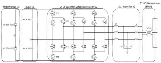
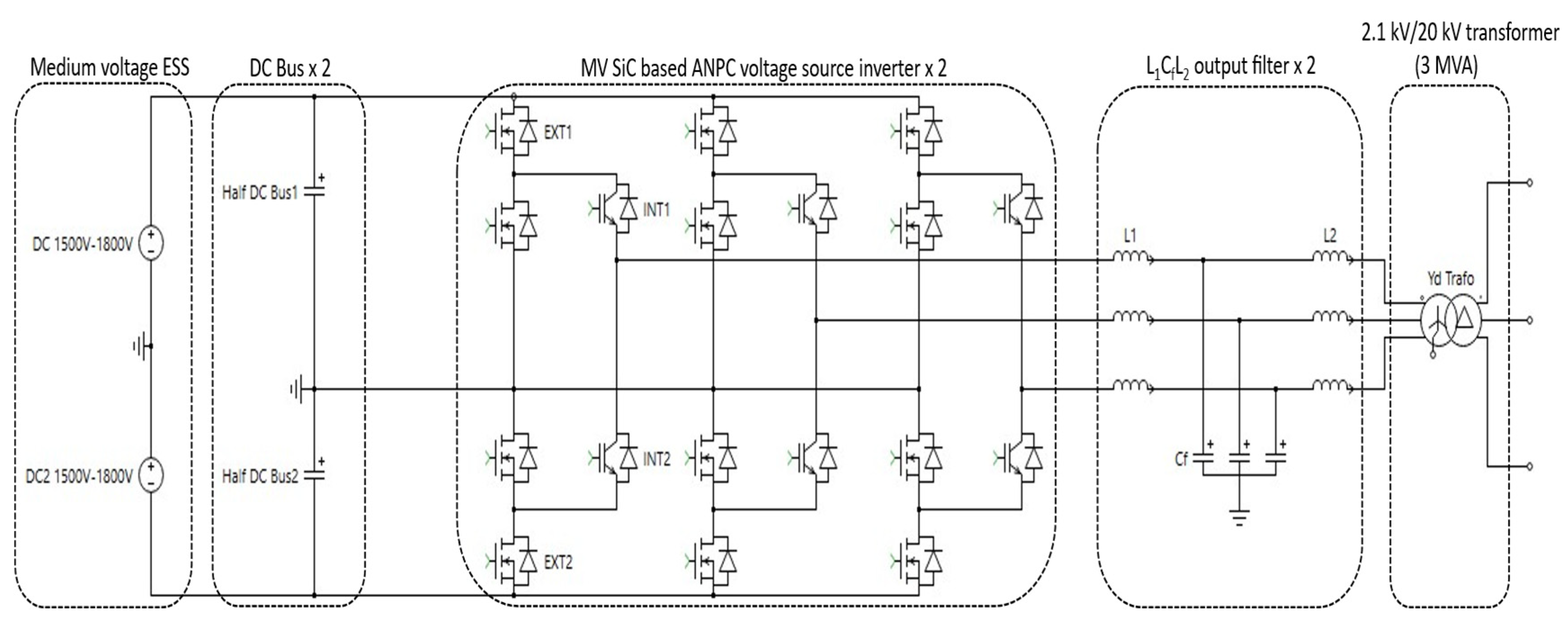
The second topology consists of a 3 MVA ANPC DC/AC Power Conversion Unit (PCU) [17] including two 1.5 MVA Power Converter Modules (PCMs). The PCU operates with a 3 kV input voltage, enabling the series connection of two battery racks with a grounded midpoint (Figure 2). Therefore, the complete PCU requires two DC buses, two 1.5 MVA ANPC converters, and two three-phase ANPC output filters. The ANPC topology provides three voltage levels. A variety of modulation types can be utilized to regulate switching operations. In this particular instance, an Outer Switch Modulation Mode (OSMM) is employed [18].
Figure 2.
3 MVA medium-voltage ANPC DC/AC PCU for comparison with the reference case.
This choice facilitates the reduction of switching loops inductance. The utilization of a transformer with a rating of 2.1 kV/20 kV is employed for the purpose of injecting electricity into the grid, representing a significantly higher voltage level compared to the reference case.
Each individual leg of the circuit is composed of six switches, indicating that a total of three 2 L power modules are required to form a single leg of the DC/AC converter. The power modules are composed of two switches. Two distinct categories of power modules have been implemented: MOS 1 and MOS 2 (3.3 kV/750 A), and IGBT 1 (3.3 kV/600 A). The DC Bus utilizes a total of 12 capacitors, each with a capacity of 220 µF, a voltage rating of 1.9 kV, and a current rating of 65 A (see Table 5).
The same calculation method as in the LV configuration is used to determine the LCL filter parameters reported in Table 4 [19], ensuring an iso-comparative basis from Table 2 with the values presented in Table 3.
Table 4.
3 MVA LCL filter, MV configuration converter; two LCL filters are required for the complete PCU (2 × 1.5 MVA).
2.5. DC Capacitor Sizing and LCI Mass Assessment
The capacitor banks were selected based on the DC bus current loading and the RMS current capability of the commercial capacitor references chosen [20]. The simulated DC Bus RMS currents are 887 A for the LV converter and 221 A for the MV converter [11]. Taking into account the actual capacitor bank arrangement, with 15 capacitors per half DC bus and phase in the LV converter, and six capacitors per half DC bus and phase in the MV converter, the resulting reference current per capacitor is 29.6 A and 18.4 A, respectively. This corresponds to 29.6% and 28.3% of the rated RMS currents of the selected capacitors (100 A and 65 A, respectively). Therefore, despite the different converter ratings and DC Bus voltage levels, the selected capacitor references result in comparable relative current loads (see Table 5).
Table 5.
Electrical sizing and mass of the DC Bus capacitor banks for the LV and MV configurations.
2.6. Component Modelling Approach & Scope Boundaries
This study highlights the major design differences between low-voltage (LV) and medium-voltage (MV) converter configurations. The 3D model of the busbar is retained to accurately represent its geometry and integration within the system [17]. The cooling solution is based on standard water plates produced by ARCEL [21], which can be adjusted in length to match the required geometry. Data provided by CEFEM [22] are used to compare the LV and MV transformer configurations. The characteristics of the DC capacitors are extracted from ZES manufacturer data [20], while the LCL filter is also considered based on CEFEM manufacturer data [22]. For clarity and transparency, the scope of the present study is limited to the major power electronic and thermal management components directly involved in the power conversion process (see Table 6). Fuses, circuit breakers, and the frame are therefore excluded from the present component-level assessment, as they primarily relate to protection and mechanical integration rather than to the power conversion itself. These components nevertheless remain important for a complete system-level comparison, particularly when considering the specific insulation, safety, protection, and mechanical requirements associated with LV and MV architectures. Their detailed assessment would require a broader integration-oriented study and is therefore considered beyond the scope of the present work.
Table 6.
Components Considered for the LCA analysis.
3. Methodology and LCA Calculations
3.1. LV vs. MV Bill of Materials
This study underscores the variation in design between the low-voltage and medium-voltage converters. Power modules of varying dimensions/technologies are implemented, consequently resulting in disparate electrical performances (see Table 1). The calculation of the output filter is of particular importance (see Table 2). The capacitors are among the most significant components differentiating the two converter configurations (see Table 5). The technical and dimensional characteristics of the power components were derived from the 3D models and manufacturer data reported in Table 6.
3.2. Goal & Scope of the LCA Analysis
The objective of the LCA analysis set out in the present article is to compare the environmental impacts associated with the manufacturing of two energy storage systems (ESS) at the utility scale (>3 MVA), considering the same power delivered (15 MVA) by two different configurations. The analysis is centred on the manufacturing stage of the life cycle of the unitary product, i.e., a DC-AC converter, in the two different voltage configurations, corresponding to LV and MV scenarios. The hypothesis is that the other stages (e.g., installation, operation, and disposal) remain relatively constant between the two configurations under consideration in order to facilitate a fair comparison. Consequently, the approach could be defined as “cradle-to-gate” from the perspective of product manufacturing. Due to the intrinsic difference in the converter power outputs, the functional unit (FU) defined as 15 MVA of power output, delivered to the user, applicable to both standard LV and MV configurations, in the following setup:
- Six PCU of 2.5 MVA each for the LV configuration, connected in parallel.
- Five PCU of 3 MVA each for the MV configuration, connected in parallel.
For a fair LCA comparison, both setups are equivalent in terms of service delivered and parallel-type connections, while having different bills of materials and number of sub-components required to reach the same service. This approach is defined to maintain a fair comparability between different rated-power systems while granting a common delivered service as basis of comparison.
Overall, this study should be viewed as a screening-level comparative assessment intended to identify the principal environmental implications associated with the two converter technologies. Although all systems were modelled using consistent databases, allocation procedures, and impact assessment methods, uncertainty associated with inventory data and background processes remains. Future studies may potentially expand the analysis through sensitivity testing and probabilistic uncertainty assessments of key parameters, particularly material quantities, component inventories, and operational assumptions.
3.3. Life Cycle Inventory (LCI) Analysis
The Life Cycle Inventory (LCI) of the present study is reported in Table 7 considering the total mass of sub-components for each of the two compared configurations; i.e., the components required to deliver the selected functional unit of the system (15 MVA of electricity power). This approach enables the quantification of masses involved while preserving the confidentiality of the specific Bill of Materials.
Table 7.
Life Cycle Inventory (LCI) of LV and MV configurations for 15 MVA, to be delivered (FU).
As previously stated, the final mass of the two systems is different, as is their unitary rated power, but, as anticipated, in order to effectively compare the two proposed configurations, a common functional unit is defined in Goal and Scope; i.e., 15 MVA of rated power delivered by the system. Consequently, to reach this output power, a different number of DC/AC Power Converters for the two scenarios is required; i.e., six PCU of 2.5-MVA in the LV configuration and five PCU of 3-MVA in the MV configuration.
A specific degree of precision is implemented during the assembly process, with the objective of minimizing the relative weight of the components. In the present LCA study, the components enumerated in Table 7 were all incorporated into the life cycle assessment analysis, and they represent the total masses of sub-components constituting the configurations able to achieve the defined rated-power of 15 MVA. These items were also the target of the applied innovation process in the field of power electronics.
The LCA models examined in this article have been developed on GaBi™ 10.9.0.31 software [23] (database version: 2026.1), wherein suitable datasets have been selected from the ecoinvent© 3.12 (allocation, cut-off by classification) database [24], based on the manufacturers’ information. In the interest of maintaining confidentiality, only the total masses of components is disclosed, while the selected datasets are reported in the Supplementary Materials (Table S5). From a geographical perspective, the primary data sources for Europe are predominantly referenced. Additional information is provided upon request to the authors.
4. Discussion
4.1. LV Configuration (FU)
The environmental impact assessment is performed in accordance with the Environmental Footprint (EF) 3.1 methodology [25]. This method encompasses 25 midpoint impact categories associated with a specific indicator. For the present LCA study, eight of the most representative impact categories (according to [26] and their relative significance for the topic as per [27]) are considered priority for the LCA of the DC/AC power converters; i.e., Acidification, Climate Change -total, Human Toxicity -total, Land Use, Ozone Depletion, Resource Use -fossil, Resource Use -mineral and metals, and Water Use. These indicators collectively cover the environmental mechanisms expected to be most strongly influenced by material-intensive electrical equipment, including greenhouse-gas emissions, depletion of abiotic resources, water demand, toxicity-related impacts, and land occupation. The selection was established before interpretation of the results and was therefore independent of the comparative environmental performance of the assessed alternatives. To ensure transparency and avoid selective reporting, results for all twenty-five EF 3.1 impact categories are provided in the Supplementary Materials (Table S1 for LV and Table S2 for MV configurations, respectively, as well as their relative variations in Table S3). The results of the assessment are referenced for the functional unit of the study (i.e., 15 MVA of rated power) and presented for each configuration; finally, the main outcomes are compared and discussed.
In this section, the global results of the life cycle assessment (LCA) for the manufacturing of the standard LV configuration are examined to deliver 15 MVA (FU). These results can be found in Table 8, split per sub-component, and finally expressed for the functional unit of the analysis.
Table 8.
Impact Assessment of the 15 MVA (FU) of the LV configuration.
The results of the study indicate that the overall impact assessment associated with the LV configuration is 6.14 × 10+5 kg CO2 eq. for the Climate Change category (mostly known as Global Warming Potential, GWP), which is globally associated with the environmental footprint of the system.
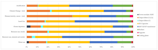
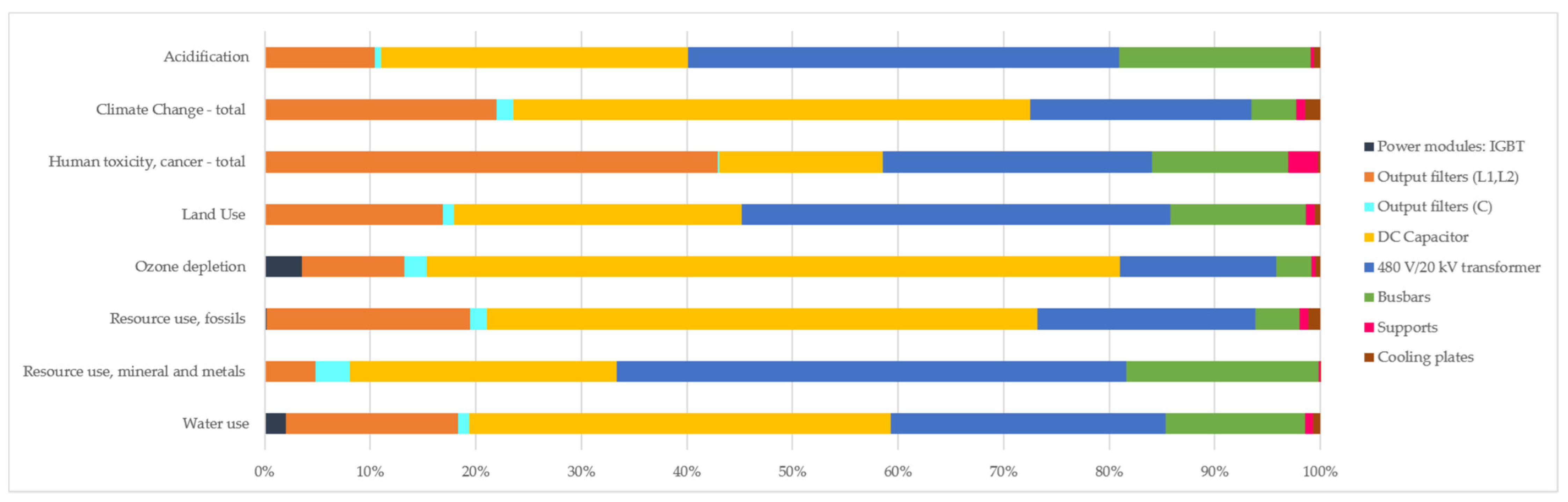
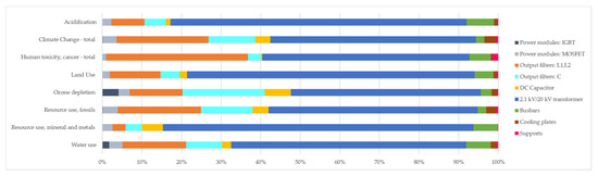
As a further step, the contribution analysis is introduced to identify the relative relevance, per each impact category, associated with each considered converter’s component. As illustrated in Figure 3, the analysis indicates that the most significant contribution is derived from the production of DC capacitors, a process that necessitates massive utilization of chemicals and resources. Furthermore, the 480 V/20 kV Transformer has been identified as a significant contributor to environmental impact, primarily due to its reliance on cast iron and the substantial energy and resource (e.g., water) consumption inherent in its manufacturing process.
Figure 3.
Contribution analysis on LCIA results for 15 MVA (FU) in LV configuration.
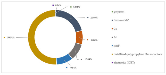
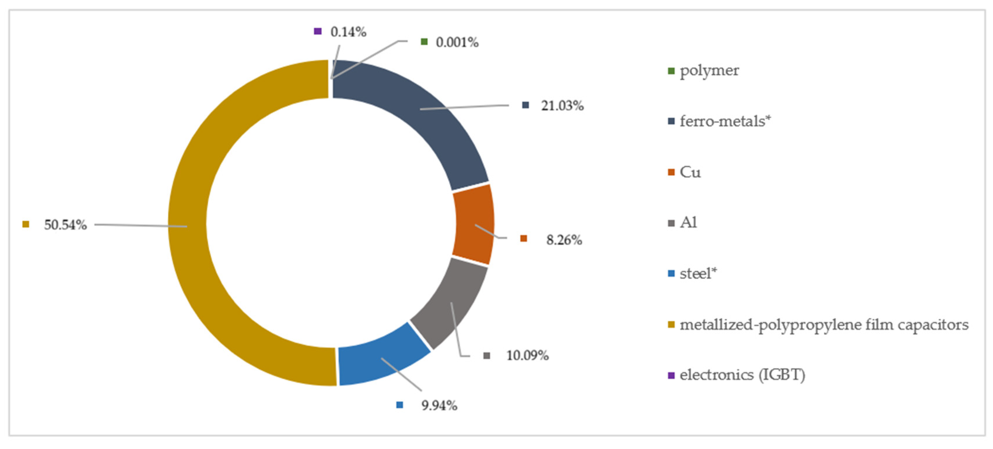
A further investigation focuses on materials use and contribution breakdown, considering one of the most representative and well-known indicators, i.e., Climate Change-total. As illustrated in Figure 4, in the LV configuration, the capacitor production accounts for the highest share (50.54%) of Climate Change impacts, almost counterbalanced by metals (49.32%). In this category, the highest contribution to GWP is due to ferro-metals (21.03%), including nickel–chromium and cast iron alloys, followed by aluminium and stainless steel, both ranging around 10%.
Figure 4.
Materials contribution on Climate change-total for 15 MVA (FU) in LV configuration. * Ferro-metals is a material class including different kinds of metals and alloys (e.g., Ni–Cr alloy, cast iron), excluding pure steel, which is present in transformer and busbars; steel instead refers to the electrical steel sheet used in the LCL filter inductors (magnetic core) and mechanical supports.
The result of this study confirms the calculation of the contribution analysis, and it is also justified by the high mass of the related components (order of magnitude: tons) and by the huge resources consuming (energy, water) value-chains of the identified hotspots.
4.2. MV Configuration (FU)
Table 9 reports the results of Life Cycle Impact Assessment (LCIA) for the MV configuration, split per each sub-component and finally expressed as for the FU (15 MVA). In detail, the MV configuration presents 2.41 × 10+5 kg CO2 eq. for Climate change-total as the main indicator of the overall environmental footprint of the system.
Table 9.
Impact Assessment for 15 MVA (FU) in MV configuration.
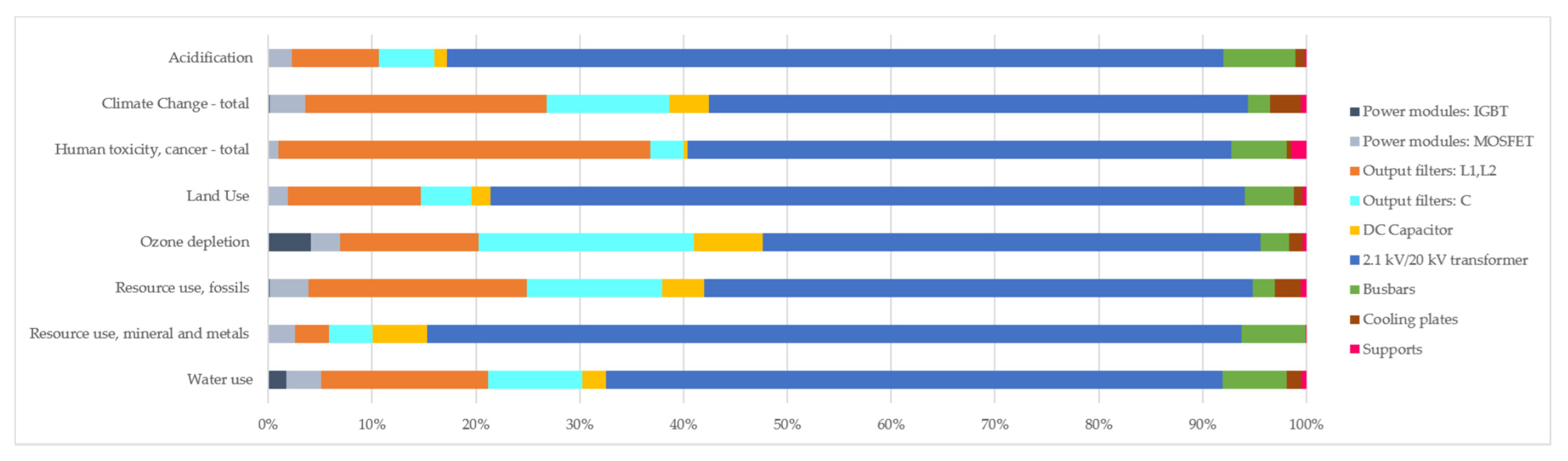
The contribution analysis of the components provides insight into the relevance of these entries to each impact category (Figure 5). In this configuration, the manufacturing of the 2.1 kV/20 kV transformer exhibits the most significant impact, while the DC capacitor substantially reduces its relevance with respect to the LV configuration. This further underscores the substantial impact of the processing route for these components, attributable to the substantial masses involved and the considerable resource consumption (materials and energy) required.
Figure 5.
Contribution analysis for LCIA results for the MV configuration delivering 15 MVA (FU).
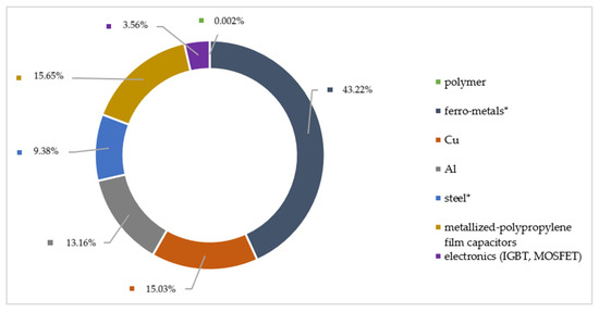
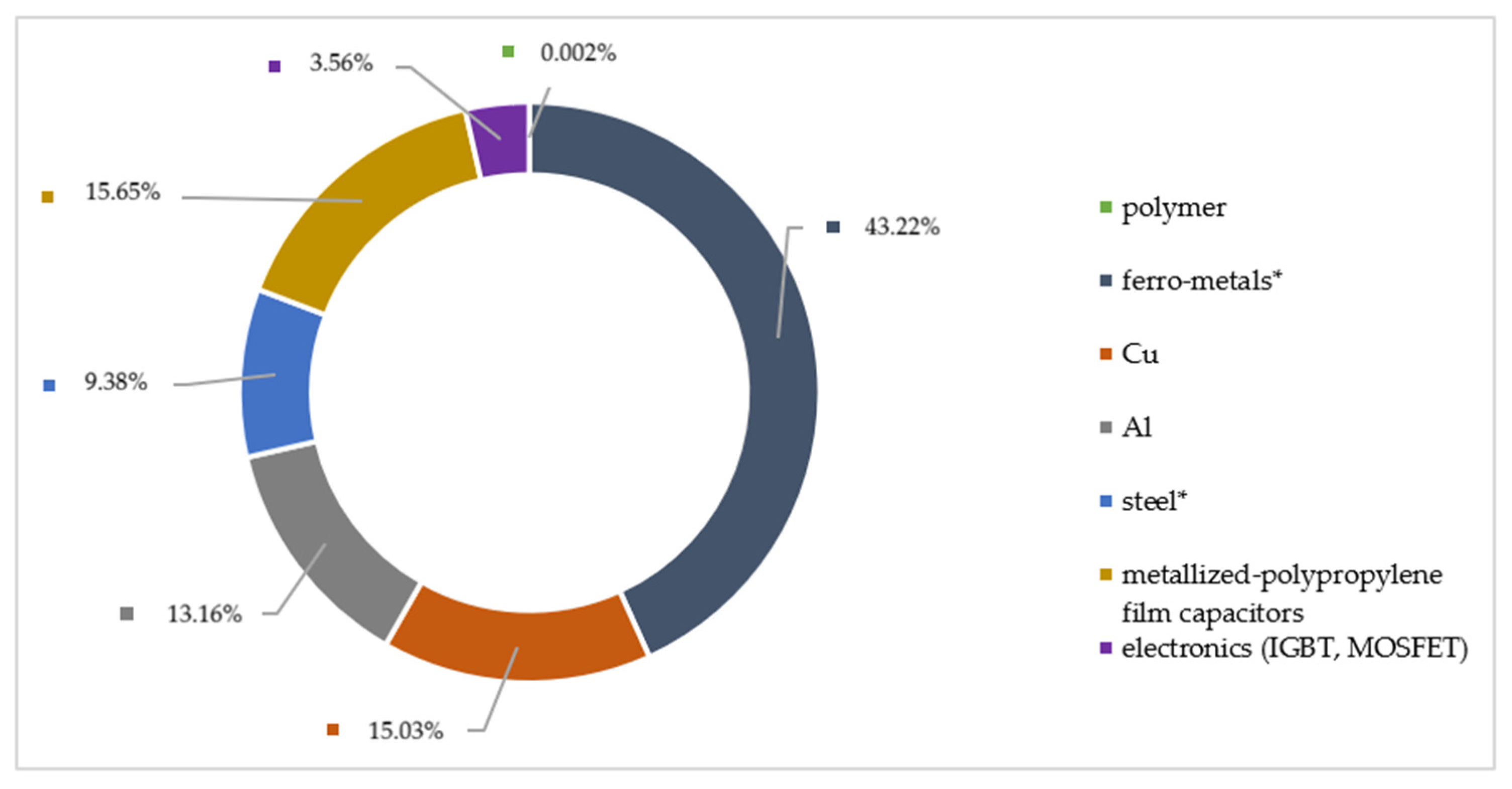
A breakdown analysis is conducted on the utilization of materials, focusing on the most salient impact indicator, i.e., Climate Change-total. As illustrated in Figure 6, the distribution of shares by material on the selected EF 3.1 indicator reveals that ferro-metals hold the predominant percentage at 43.22%, followed by capacitors (15.65%) and copper (15.03%). Below 15% is the contribution of other metals, e.g., aluminium (13.16%) and stainless steel (9.37%). As previously observed, the manufacturing process of metals is notably material- and energy-intensive, thereby significantly contributing to the overall environmental impact assessment of the selected product, while capacitor production was also confirmed to be quite energy demanding.
Figure 6.
Materials contribution on Climate change-total for the MV configuration (FU). * Ferro-metals is a material class including different kind of metals and alloys (e.g., Ni–Cr alloy, cast iron), excluding pure steel, which is present in transformers and busbars; steel instead refers to the electrical steel sheet used in LCL filter inductors (magnetic core) and mechanical supports.
4.3. Comparison of Configurations
The comparative LCA performed on the two different Utility ESS configurations (LV vs. MV), both providing the same rated power output (15 MVA), points out that the MV solution has a minor environmental impact with respect to the standard setup. Indeed, the total results of the two configurations, per each considered EF 3.1 impact category, are reported in Table 10.
Table 10.
Comparison of total LCIA results (LV vs. MV configuration) for FU (15 MVA).
The comparison between standard LV and MV converter architectures reveals that the environmental advantages of the MV solution are consistently observed across the selected EF 3.1 impact categories, although the magnitude and drivers of these improvements differ according to the environmental mechanism considered.
From a Climate Change-total (GWP) perspective, the MV configuration exhibits an approximately 61% reduction compared with the LV power electronics technology (2.41 × 10+5 versus 6.14 × 10+6 kg CO2 eq., namely two-thirds of GWP saving per functional unit). This result is primarily attributed to the substantial reduction in DC capacitor requirements and to the lower overall material demand enabled by higher-voltage operation. The contribution analyses presented in Figure 3, Figure 4, Figure 5 and Figure 6 indicate that capacitors represent one of the dominant hotspots of the LV configuration, owing to their energy-intensive manufacturing processes and associated material requirements (50% material impact for GWP). The reduction of these components in the MV design therefore translates directly into lower greenhouse-gas emissions.
A similar trend is observed for Resource Use–Fossils, where the MV configuration reduces fossil resource demand by approximately 62%. Since this impact category is strongly influenced by cumulative energy requirements embedded in material production, the reduction confirms that the optimized architecture requires significantly lower upstream energy consumption throughout its manufacturing chain. The categories Acidification, Human Toxicity, Land Use, and Ozone Depletion exhibit reductions ranging from approximately 47% to 70%. These results follow the same general pattern observed for Climate Change and Resource Use, as they are largely influenced by the extraction, processing, and manufacturing activities associated with metals, polymers, and electronic components. Therefore, the overall lower-material inventory of the MV configuration leads to a broad reduction in environmental burdens across these impact pathways.
Resource use–minerals & metals, indeed, shows a comparatively lower reduction than other impact categories because, despite the overall mass decrease enabled by the MV configuration, the system still relies on a substantial amount of metal-intensive components. In particular, the continued use of transformers, output filters, busbars, cooling plates, and metallic supports maintains a relevant demand for ferrous metals, aluminium, copper, and other mineral-based materials.
Globally, particular consideration should be given to hotspot analysis and resulting evidence. The contribution analysis originates primarily from the upstream production and processing of sub-components, including electronic and metallic materials, represented through the background datasets adopted from ecoinvent 3.12. As the assessment relies on generic supply-chain data and the EF 3.1 characterization method, the reported results describe potential impacts along the life cycle and should not be interpreted as an assessment of site-specific conditions. From a more technological point of view, while the optimization of capacitors and other converter components substantially reduces impacts related to Climate change and Resource consumptions, the influence of these improvements on other indicator results is partially offset by the materials-demanding production processes. Consequently, environmental benefits of the MV architecture are comparatively different for the selected impact indicator, while the relative saving is always above 37%.
Overall, the results indicate that the environmental superiority of the MV configuration is not limited to a single indicator but extends across multiple environmental dimensions. Additionally, the analysis also highlights that the mechanisms responsible for these improvements vary according to the impact category considered, underlining the importance of adopting a multi-indicator LCA perspective when evaluating alternative converter architectures.
In conclusion, an optimized design and mass balance (total weigh saving is 32% in MV setup), accompanied by a careful selection of components, has allowed reduction of the presence of the most impacting materials, with positive reflections on the overall impact assessment of the system without compromising its functionality.
5. Conclusions
The rapid deployment of renewable electricity generation and the parallel need for large-scale Energy Storage Systems (ESS) capable of ensuring grid stability while minimizing environmental burdens drive researchers toward more sustainable and efficient solutions. As power ratings increase, conventional low-voltage (LV) battery energy storage architectures reveal structural and environmental limitations, particularly due to high currents, oversized components, and material-intensive designs. In this context, medium-voltage (MV) solutions based on advanced power electronics emerge as a promising alternative; yet, their environmental performance has remained insufficiently quantified.
To address this gap, this paper provides a combined technical and environmental comparison between a conventional LV DC/AC converter and an MV converter employing 3.3 kV silicon carbide (SiC) technology. The environmental evaluation was conducted using a Life Cycle Assessment (LCA) approach, following [28,29] ISO 14040/14044 standards and the Environmental Footprint (EF) 3.1 methodology. The analysis adopted a cradle-to-gate perspective and focused on the manufacturing phase, while installation, operation, and end-of-life stages were outside the system boundary. The functional unit was defined as one DC/AC power converter for utility-scale ESS, ensuring a comparison between the two configurations despite differing rated powers and internal bills of materials.
The LCA results indicate a lower environmental impact for the MV configuration, reporting a GWP total impact of 2.41 × 10+5 kgCO2 eq./FU (equal to 1.61 × 10+4 kgCO2 eq./MVA). Across all selected impact categories—including Climate Change, Acidification, Ozone Depletion, Resource Use (both fossil and minerals & metals), and Land and Water Use—the MV solution shows substantial reductions, with Climate Change impacts decreasing by approximately 61% compared to the LV reference case, expressing a global GWP of 6.14 × 10+5 kgCO2 eq./FU (equal to 4.09 × 10+4 kgCO2 eq./MVA). These improvements are primarily driven by a more efficient design, reduced quantities of high-impact components (notably DC capacitors), and an optimized bill of materials enabled by higher operating voltages. In addition, the MV converter exhibits a markedly higher power-to-mass ratio (almost doubled), highlighting improved material efficiency and power density. This improvement is associated with the use of 3.3 kV SiC semiconductors and the resulting higher operating voltage and power density.
Overall, the results indicate a potential technical and environmental advantage of the MV configuration within the scope and assumptions of the present study. However, these results should be interpreted considering the limitations of the study, particularly the cradle-to-gate system boundary, which excludes lifetime operation and end-of-life stages, as well as the assumptions underlying the electrical-performance assessment. Future work could also include uncertainty analysis, detailed lifetime operation and end-of-life scenarios, and experimental validation of the electrical-performance assumptions.
Finally, the integration of performance analysis and LCA can provide valuable support for guiding sustainable design choices in next-generation power electronics and energy infrastructures.
Supplementary Materials
The following supporting information can be downloaded at: https://www.mdpi.com/article/10.3390/electricity7040112/s1.
Author Contributions
Conceptualization and LCA methodology, G.A.C.; power electronics design and simulation, J.M. and A.B.; LCA inventory and impact analysis, G.A.C.; Writing—original draft preparation, G.A.C. and J.M. All authors contributed to reviewing, editing, and refining the manuscript. All authors have read and agreed to the published version of the manuscript.
Funding
This research was funded by the European Union under the Horizon 2020 program, TALENT project (Grant Agreement No. 864459, DOI: 10.3030/864459), coordinated by Fundación CARTIF.
Data Availability Statement
Data is contained within the article and Supplementary Material.
Acknowledgments
The authors would like to acknowledge the valuable contribution of Luc Bimmel, who participated in the preliminary design study of the reference converter and conducted simulation work on the advanced converter’s topologies. The authors also gratefully acknowledge Didier Prignon from CEFEM for providing material data, including copper and iron mass breakdowns for distribution transformers and inductors, which were essential for the life cycle assessment of the study. The authors would also like to thank Jean-François Roche from ARCEL for his valuable contributions to the design of the medium-voltage power stack. Finally, the authors thank all collaborators involved in technical discussions and exchanges that contributed to this work.
Conflicts of Interest
Author Gloria Anna Carallo was employed by the company RINA Consulting S.p.A.–Headquarter. The remaining authors declare that the research was conducted in the absence of any commercial or financial relationships that could be construed as a potential conflict of interest.
Abbreviations
The following abbreviations are used in this manuscript:
| 2L | Two Level power module |
| AC | Alternating Current |
| ANPC | Active Neutral Point Clamped |
| BESS | Battery Energy Storage System |
| DC | Direct Current |
| EF | Environmental Footprint |
| ESS | Energy Storage System |
| FU | Functional Unit |
| GWP | Global Warming Potential |
| IGBT | Insulated Gate Bi-Polar Transistor |
| LCA | Life cycle assessment |
| LCI | Life Cycle Inventory |
| LCIA | Life Cycle Impact Assessment |
| LV | Low Voltage |
| MOSFET | Metal Oxide Field Effect Transistor |
| MV | Medium Voltage |
| OSMM | Outer Switch Modulation Mode |
| PC | Power Converter |
| PCM | Power Converter Module |
| PCU | Power Conversion Unit |
| PV | photovoltaic |
| RES | Renewable energy sources |
| Si | Silicon |
| SiC | Silicon Carbide |
References
- International Renewable Energy Agency (IRENA). World Energy Transitions Outlook 2024: 1.5 °C Pathway; International Renewable Energy Agency (IRENA): Abu Dhabi, United Arab Emirates, 2024; Available online: https://www.irena.org/-/media/Files/IRENA/Agency/Publication/2024/Nov/IRENA_World_energy_transitions_outlook_2024.pdf (accessed on 10 September 2026).
- International Energy Agency (IEA). Global Energy Review 2026; International Energy Agency (IEA): Paris, France, 2026; Available online: https://www.irena.org/-/media/Files/IRENA/Agency/Publication/2026/Jul/IRENA_DAT_RE_Statistics_2026.pdf (accessed on 10 September 2026).
- Bisinella, V.; Christensen, T.H.; Astrup, T.F. Future scenarios and life cycle assessment: Systematic review and recommendations. Int. J. Life Cycle Assess. 2021, 26, 2143–2170. [Google Scholar] [CrossRef] [Scilit]
- Baudais, B.; Ben Ahmed, H.; Jodin, G.; Degrenne, N.; Lefebvre, S. Life Cycle Assessment of a 150 kW Electronic Power Inverter. Energies 2023, 16, 2192. [Google Scholar] [CrossRef] [Scilit]
- Bier, A.; Wiss, O.; Messaoudi, P. A 3 kV, 18 kW medium-voltage PV plant demonstrator. In Proceedings of the COSYS DC 2017—International Conference on Components and Systems for DC Grids, Grenoble, France, 14–15 March 2017; Available online: https://cea.hal.science/cea-03780308 (accessed on 10 September 2026).
- Biela, J.; Schweizer, M.; Waffler, S.; Kolar, J.W. SiC versus Si—Evaluation of Potentials for Performance Improvement of Inverter and DC–DC Converter Systems by SiC Power Semiconductors. IEEE Trans. Ind. Electron. 2011, 58, 2872–2882. [Google Scholar] [CrossRef] [Scilit]
- Radwan, M.; Paulasto-Kröckel, M.; Vuorinen, V. Cradle-to-Gate Life Cycle Assessment of Si IGBT and SiC MOSFET Power Modules. In 2025 IEEE Conference on Technologies for Sustainability (SusTech); IEEE: Los Angeles, CA, USA, 2025; pp. 1–5. [Google Scholar]
- Nguyen, D.-H.; Martin, J.; Gaillard, A.; Tran, Q.-T. Medium Voltage Conversion Systems with Integrated Galvanic Isolation for Hybrid Photovoltaic Plants. Solar 2026, 6, 18. [Google Scholar] [CrossRef] [Scilit]
- ISO 14040:2021; Environmental Management—Life Cycle Assessment—Principles and Framework. International Organization for Standardization: Geneva, Switzerland, 2021.
- ISO 14044:2021; Environmental Management—Life Cycle Assessment—Requirements and Guidelines. International Organization for Standardization: Geneva, Switzerland, 2021.
- Plexim GmbH. PLECS. Available online: https://www.plexim.com/products/plecs (accessed on 10 September 2026).
- Sattar, M.; Masud, U.; Farooqi, A.R.; Akram, F.; Khan, Z. Parametric Design of an LCL Filter for Harmonic Suppression in a Three-Phase Grid-Connected Fifteen-Level CHB Inverter. Designs 2026, 10, 6. [Google Scholar] [CrossRef] [Scilit]
- Dannehl, J.; Liserre, M.; Fuchs, F.W. Filter-Based Active Damping of Voltage Source Converters With $LCL$ Filter. IEEE Trans. Ind. Electron. 2011, 58, 3623–3633. [Google Scholar] [CrossRef] [Scilit]
- Liserre, M.; Blaabjerg, F.; Hansen, S. Design and Control of an LCL-Filter-Based Three-Phase Active Rectifier. IEEE Trans. Ind. Appl. 2005, 41, 1281–1291. [Google Scholar] [CrossRef] [Scilit]
- Said-Romdhane, M.; Naouar, M.; Belkhodja, I.; Monmasson, E. An Improved LCL Filter Design in Order to Ensure Stability without Damping and Despite Large Grid Impedance Variations. Energies 2017, 10, 336. [Google Scholar] [CrossRef] [Scilit]
- Komatsu, H.; Katayama, T.; Kawakami, N. Development of Large-Capacity Converter for Battery Energy Storage Systems. In 2018 International Power Electronics Conference (IPEC-Niigata 2018-ECCE Asia); IEEE: Niigata, Japan, 2018; pp. 1346–1350. [Google Scholar]
- Beye, M.L.; Bimmel, L.; Bier, A.; Martin, J. Multilayer busbars for medium voltage ANPC converter dedicated to battery energy storage systems. In 2022 24th European Conference on Power Electronics and Applications (EPE'22 ECCE Europe); IEEE: New York, NY, USA, 2022; Available online: https://ieeexplore.ieee.org/document/9907657 (accessed on 10 September 2026).
- Jiao, Y.; Lu, S.; Lee, F.C. Switching Performance Optimization of a High Power High Frequency Three-Level Active Neutral Point Clamped Phase Leg. IEEE Trans. Power Electron. 2014, 29, 3255–3266. [Google Scholar] [CrossRef] [Scilit]
- Shah, S.; (Decentralized Renewable Energy Technology, Corporate Research & Technologies, SIEMENS, Bangalore 560100, India). Step-by-Step Design of an LCL Filter for Three-Phase Grid Interactive Converter. Unpublished work. 2015.
- ZEZSILKO-KATALOG-ELECTRONICS. Available online: https://www.zez-silko.es/data/uploadHTML/files/download-pe-power-electronics/dc-link-standardni.pdf (accessed on 10 September 2026).
- ARCEL Chambre à Eau WPM. Available online: https://www.arcel.fr/fr/plaques-a-eau/3335-chambre-a-eau-wpm.html (accessed on 26 August 2026).
- Cefem Group. Available online: https://www.cefem-group.com/ (accessed on 10 September 2026).
- Sphera®. GaBi ts-Software for Life Cycle Assessment. Available online: https://sphera.com/solutions/product-stewardship/life-cycle-assessment-software-and-data/lca-for-experts/ (accessed on 10 September 2026).
- Ecoinvent®. The Ecoinvent Database Is a Life Cycle Inventory (LCI) Database That Supports Various Types of Sustainability Assessments. Available online: https://ecoinvent.org/the-ecoinvent-database/ (accessed on 10 September 2026).
- European Commission, Joint Research Centre. Supporting Information to the Characterisation Factors of Recommended EF Life Cycle Impact Assessment Methods: Version 2, from ILCD to EF 3.0; Publications Office: Luxembourg, 2018. [Google Scholar]
- European Commission, Joint Research Centre. Global Normalisation Factors for the Environmental Footprint and Life Cycle Assessment; Publications Office: Luxembourg, 2017. [Google Scholar]
- Rosenbaum, R.K. Selection of Impact Categories, Category Indicators and Characterization Models in Goal and Scope Definition. In Goal and Scope Definition in Life Cycle Assessment. LCA Compendium—The Complete World of Life Cycle Assessment; Curran, M., Ed.; Springer: Dordrecht, The Netherlands, 2017. [Google Scholar] [CrossRef] [Scilit]
- ISO 14040:2006; Environmental Management Life Cycle Assessment Principles and Framework. ISO: Geneva, Switzerland, 2006. Available online: https://www.iso.org/standard/37456.html (accessed on 10 September 2026).
- ISO 14044:2006; Environmental Management Life Cycle Assessment Requirements and Guidelines. ISO: Geneva, Switzerland, 2006. Available online: https://www.iso.org/standard/38498.html (accessed on 10 September 2026).

Disclaimer/Publisher’s Note: The statements, opinions and data contained in all publications are solely those of the individual author(s) and contributor(s) and not of MDPI and/or the editor(s). MDPI and/or the editor(s) disclaim responsibility for any injury to people or property resulting from any ideas, methods, instructions or products referred to in the content. |
© 2026 by the authors. Licensee MDPI, Basel, Switzerland. This article is an open access article distributed under the terms and conditions of the Creative Commons Attribution (CC BY) license.