


Abstract
With the increase in voltage levels, higher requirements are imposed on the energy-dissipation capability of high-voltage direct current (HVDC) networks. Existing energy-dissipation schemes cannot satisfy the demands of future HVDC systems. In this paper, a composite energy-dissipation branch circuit based on liquid metal, zinc oxide varistors, and damping resistors is proposed for HVDC circuit breakers. First, the self-constricting arc initiation mechanism and energy-dissipation characteristics of gallium–indium–tin liquid metal are studied. The results show that the energy-dissipation process exhibits an obvious stage-wise characteristic. Subsequently, an energy-dissipation topology incorporating liquid metal elements is established. A simulation model for the liquid-metal module is developed using the Mayr arc theory, and the conductance evolution during arc initiation is simulated. The model is combined with a hybrid HVDC circuit breaker model for analysis. Finally, a composite energy-dissipation branch circuit is constructed. The energy allocation among different components and the corresponding power density are evaluated. In the case of connecting three liquid-metal components in series, the energy density reached 0.248 kJ/cm3, representing a 22.2% increase compared to the original. The results support the coordinated application of liquid-metal modules and conventional absorption units in HVDC circuit breakers.
1. Introduction
HVDC circuit breakers play an essential role in DC transmission networks by enhancing system reliability and operational flexibility [1,2]. Existing HVDC breaker technologies can be broadly classified into mechanical designs [3,4] and hybrid designs [5,6]. Owing to their superior overall performance, hybrid configurations have become the predominant solution in commercial HVDC applications [7]. A typical hybrid breaker is composed of a current-carrying path, a semiconductor-based commutation path, and an absorption circuit [8]. During fault interruption, the absorption circuit suppresses transient overvoltages and absorbs fault energy released by the system. As a result, its capability has a significant influence on the fault-clearing performance of the breaker. The manner in which fault energy is managed also affects the interruption duration and overall system efficiency, thereby influencing equipment volume and economic cost [9,10]. Nevertheless, conventional approaches face increasing challenges in meeting the demands of next-generation HVDC networks. HVDC circuit breakers are indispensable core protection and regulation equipment for scenarios including DC power grids and island DC energy-storage microgrids. Taking cross-border DC interconnection projects such as the Mediterranean Solar Plan and DESERTEC as research objects, Reference [11] demonstrates the improvement effect of transmarine HVDC interconnections on the dynamic stability of the European main grid, and summarizes operational challenges including coordinated control of multiple DC links and cross-regional fault propagation. By investigating practical energy-storage projects on multiple European isolated islands, Reference [12] analyzes the constraints affecting the selection of various energy-storage schemes. From the two perspectives of intercontinental long-distance DC power transmission and flexible regulation of on-island local DC microgrids, these two studies jointly establish a complete research framework for flexible resources in the Mediterranean AC-DC hybrid power grid. In the Mediterranean power system, transmarine HVDC tie lines and DC buses of island energy-storage systems share the characteristics of fast fault current rise and massive accumulation of transient fault energy. Without high-performance hybrid HVDC circuit breakers capable of millisecond-level fault isolation and efficient energy dissipation, DC short-circuit faults will rapidly spread to the AC main grid and energy-storage devices, greatly offsetting the stability improvement benefits brought by HVDC interconnections and energy-storage systems, and may even trigger wide-area cascading power outages in severe cases. Existing research on hybrid HVDC circuit breakers mostly focuses solely on the optimization of topologies and energy-dissipation branches, while few studies analyze their adaptability targeted at the Mediterranean land–sea AC-DC hybrid grid scenario [13,14]. Meanwhile, with the continuous expansion of the transmission capacity of HVDC power grids, the traditional zinc oxide energy-dissipation scheme has to rely on increasing the quantity and volume of varistors to absorb larger fault energy. This scheme suffers from inherent drawbacks such as bulky equipment, high manufacturing cost and reduced interruption reliability, which cannot meet the construction demands of large-capacity DC power grids in the future. Therefore, it is essential to develop novel fault energy-dissipation methods.
Ga–In–Sn liquid metal has high thermal conductivity, high electrical conductivity, fluidity, and reusability. Owing to its excellent thermal conductivity, heat generated during the arc process can be rapidly transferred and removed. During the phase transition process, the liquid metal is heated and vaporized, and a large amount of heat is absorbed simultaneously. In the field of high-voltage electrical engineering, Ga–In–Sn liquid metal has been widely investigated for current-limiting applications. Wu investigated the liquid flow and contraction characteristics of liquid-metal current limiters and analyzed the pre-arc flow behavior and electromagnetic contraction mechanism of liquid metal [15,16]. The results showed that liquid-metal current limiters can effectively suppress the rising rate of fault currents. Rong also conducted a series of studies on Ga66In20.5Sn13.5 liquid-metal current limiters. The results indicated that the pre-arc process mainly includes liquid surface depression and liquid column contraction inside the through-hole. When the liquid level is high, the contraction inside the through-hole dominates the formation of the gap and further leads to arc initiation [17,18]. To further shorten the pre-arc time, an active-trigger current-limiting device was designed. A trigger signal is applied at the instant of current rise, and capacitive energy is released to the electrode to initiate the arc in advance. In this way, the pre-arc time is reduced through a small-arc-triggered large-arc process [19,20]. In practical applications, liquid-metal current limiters have been applied in medium-voltage DC systems by combining magnetically coupled current transfer methods with fast mechanical switches. Effective current limiting capability under high-current conditions has been achieved [21,22]. Zhuang further optimized the trigger structure of Ga66In20.5Sn13.5 liquid-metal devices. Compared with conventional solid trigger structures, porous trigger structures combine fast response capability and reusability, which is beneficial for improving the reliability of circuit breakers [23,24,25,26]. At present, studies on Ga–In–Sn liquid metal in the field of energy dissipation remain limited. In liquid-metal energy-dissipation devices, the arc is generated inside the liquid-metal medium. Arc Joule heat and radiant heat are transferred to the surrounding liquid metal. Under high arc temperature, the surrounding liquid metal is rapidly vaporized and heat exchange is enhanced, thereby achieving energy dissipation [27,28]. The combination of liquid-metal modules and zinc oxide arresters offers a promising solution for increasing the energy-absorption capability per unit volume during DC fault clearing.
The conventional zinc oxide energy-dissipation scheme relies on scaling up varistor arrays to accommodate large-capacity DC power grids, which suffers prominent drawbacks including bulky footprint and degraded interruption reliability. It fails to meet the development demands of future DC grids, and novel energy-dissipation technologies are therefore urgently required. In this paper, a novel high-voltage DC circuit breaker topology equipped with a liquid-metal composite energy-dissipation branch is proposed. On the basis of the traditional hybrid circuit breaker framework composed of a main branch and a transfer branch, this topology innovatively integrates liquid-metal energy-dissipation units, zinc oxide varistors and damping resistors to form a multi-stage collaborative energy-absorption loop. The full fault-breaking sequence of the circuit breaker is analyzed in detail, and the cooperative operating mechanism including branch switching, arc commutation and hierarchical energy absorption of each component is illustrated clearly. High-speed photography technology is adopted to experimentally investigate the self-pinch effect and arc energy-dissipation characteristics of liquid metal. The evolution law of arcing initiation, loop current, arcing voltage, arcing resistance and arc morphology during the entire discharge and energy-dissipation process under the self-pinch condition of liquid metal is obtained. On the PSCAD/EMTDC simulation platform [29], a circuit model of the liquid-metal energy-dissipation module is established based on the Mayr arc equation and the volt-ampere characteristic curve of liquid metal, which can characterize the equivalent nonlinear time-varying conductance during the arcing process of liquid-metal elements. This model is further combined with the conventional hybrid DC circuit breaker model to construct a composite energy-dissipation branch consisting of liquid-metal units, zinc oxide varistors and damping resistors. By comparative simulations, the variation rules of terminal voltage, terminal current and dissipated energy of the three energy-consuming media under different numbers of liquid-metal elements are explored, and the influence of the quantity of liquid-metal units on total energy-dissipation time and volumetric energy density is clarified.
2. Energy-Dissipation Principle and Characteristics of Ga–In–Sn
2.1. Principle of Energy Dissipation of Ga–In–Sn
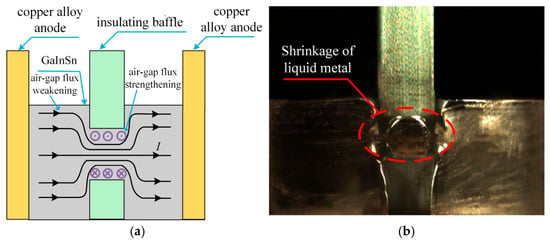
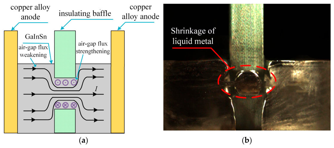
As shown in Figure 1a, arc formation in Ga–In–Sn liquid metal originates from the self-constriction phenomenon under high-current conditions. During normal operation, the current is concentrated in the flow channel, resulting in a significantly higher local current density than in the surrounding regions. As the conducting area decreases, the magnetic field generated by the current becomes stronger. When a system fault occurs, the fault current rapidly increases to several tens of kiloamperes within a few milliseconds, producing a strong electromagnetic force in the channel region. At the same time, the rapid current rise causes current concentration near the conductor corners, leading to a nonuniform current distribution with higher intensity along the outer edge of the channel. Under the combined electromagnetic action, the liquid metal is forced outward, causing the conductive path to separate and triggering arc formation.
Figure 1.
Constriction and arc initiation mechanism of Ga–In–Sn liquid metal. (a) Arc initiation principle of gallium–indium–tin liquid metal. (b) Contraction experiment of gallium–indium–tin liquid metal.
The contraction process of the Ga–In–Sn liquid metal is shown in Figure 1b. Because of its high surface tension, microscopic voids exist between the liquid metal and the insulating barrier. As the liquid metal contracts, these voids expand and gradually develop into low-pressure zones. With the continued increase in current, electrical breakdown occurs in these regions and an arc channel is established. The arc subsequently extends beyond the channel and causes a rapid increase in the equivalent resistance of the device, enabling fault-current suppression and energy absorption. Furthermore, the excellent thermal conductivity of the liquid metal allows heat generated by the arc to be transferred efficiently. Meanwhile, partial vaporization of the liquid metal absorbs a portion of the fault energy, contributing to the overall energy-absorption process.
2.2. Parameter Variation During the Liquid-Metal Energy-Dissipation Process
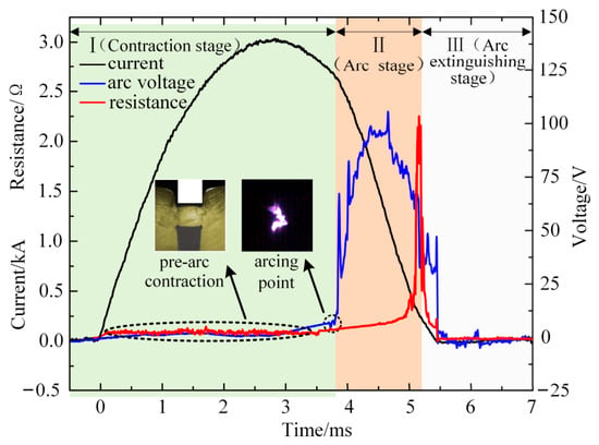
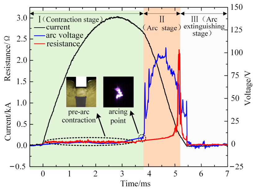
To examine the transient behavior of Ga–In–Sn liquid metal during fault-energy absorption, the voltage–current response during the discharge process is investigated. Figure 2 presents the measured voltage–current characteristics under a capacitor charging voltage of 220 V and an inductance of 0.1 mH. According to the results, the discharge process can be divided into three phases: the electromagnetic contraction phase, the arc-development phase, and the extinction phase.
Figure 2.
Voltage–current characteristics of liquid-metal energy dissipation.
During the first phase, from fault-current generation to electrical breakdown, heat is mainly produced in the channel region due to Joule heating, causing a continuous temperature rise of the liquid metal. In the second phase, the conductive path is interrupted and a discharge gap is formed. At t = 3.813 ms, breakdown occurs and an arc channel is established. The arc voltage rises rapidly, and the discharge channel expands from the flow passage toward both sides of the device. Throughout this period, the arc voltage remains close to 180 V, while the equivalent resistance is maintained at approximately 200 mΩ.
In the final phase, the discharge channel gradually contracts and disappears. Meanwhile, the amount of metal vapor increases until the chamber is largely occupied by vaporized material. The device resistance reaches its peak value during this period. Several hundred microseconds later, the liquid metal returns to its original position, and the resistance gradually recovers to the initial level. Overall, after the liquid metal breaks down to form a plasma discharge channel, the arc voltage rises continuously while the resistance increases slowly in tandem. Although the resistance changes mildly during the arcing phase with no obvious variation visually, the arc voltage is jointly determined by the arc length and plasma conductivity. During the current interruption process, the arc column is elongated, and the conductivity of plasma inside the arc decreases, which further leads to a remarkable rise in arc voltage.
The results indicate that the arc-development phase contributes most to fault-energy absorption. The entire discharge process lasts approximately 1.4 ms. A higher arc voltage in this phase corresponds to a larger power conversion capability and a greater amount of absorbed fault energy.
3. Topology and Interruption Process of the HVDC Circuit Breaker with a Composite Energy-Absorption Branch
3.1. Configuration and Operating Principle of the HVDC Circuit Breaker
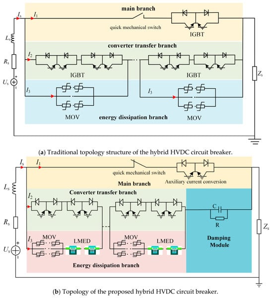
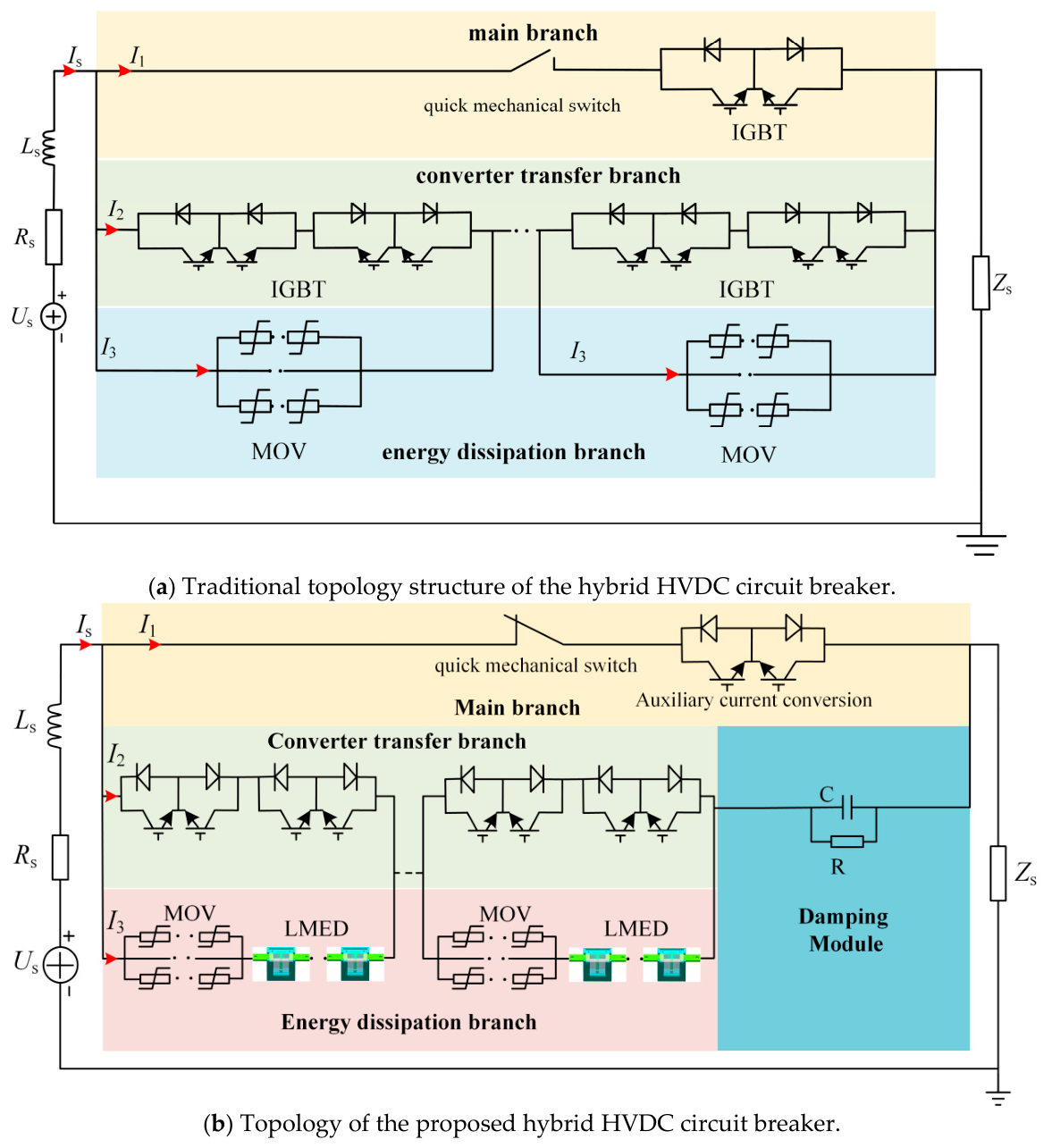
The traditional topology structure of the hybrid HVDC circuit breaker is illustrated in Figure 3a. This circuit breaker comprises three components: the main branch, the solid-state transfer switch, and the energy-dissipation branch. This section presents a composite fault-energy absorption scheme based on the series connection of liquid-metal modules, zinc oxide varistors, and a damping unit. The topology of the hybrid HVDC circuit breaker is shown in Figure 3b. The breaker consists of four parts: the main branch, the transfer branch, the damping unit, and the absorption branch. The main branch includes a fast mechanical switch (FMS) and an auxiliary commutation switch (ACS), while the absorption branch consists of a zinc oxide varistor group and liquid-metal modules. When a fault is detected, the ACS is turned off and the current is commutated to the transfer branch composed of series-connected IGBTs. The damping unit suppresses the current transfer rate and absorbs part of the fault energy.
Figure 3.
Comparison between the traditional topology structure and the proposed structure of the hybrid HVDC circuit breaker.
As the current in the main branch decreases to zero, the FMS opens under zero-current conditions. The IGBTs are then blocked, and the current is transferred to the absorption branch. The breaker voltage rises until the liquid-metal modules, zinc oxide varistors, and damping unit operate together. Before current transfer, the liquid metal remains in a low-resistance state and behaves as a conductor. The zinc oxide varistors operate first and limit the voltage to the residual level. Subsequently, arc formation occurs in the liquid-metal module, causing a rapid increase in resistance. Part of the fault energy is then absorbed by the liquid-metal module, reducing the burden on the zinc oxide varistors.
Therefore, the fault energy is shared by the liquid-metal modules, zinc oxide varistors, and damping unit. The introduction of liquid-metal modules reduces the required number of parallel varistor columns, decreases the size of the absorption branch, and improves the volumetric energy-handling capability of the HVDC circuit breaker. Compared to the traditional hybrid high-voltage DC circuit breaker topology, the proposed improved hybrid high-voltage DC circuit breaker topology can quickly dissipate energy in various forms.
3.2. HVDC Circuit Breaker Interruption and Energy-Dissipation Process
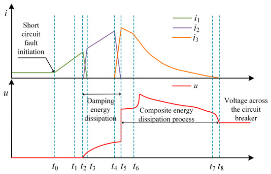
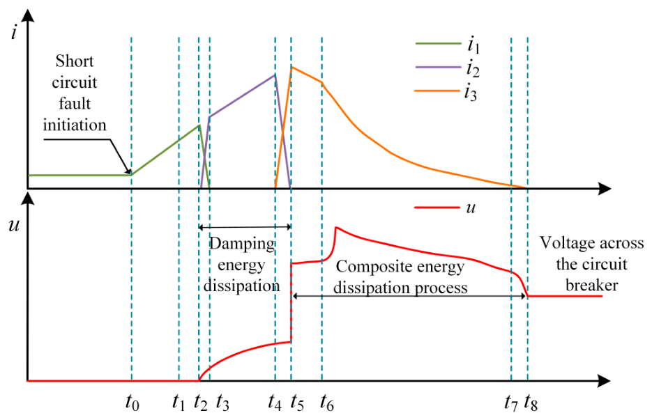
A short-circuit fault occurs at t0, causing the fault current to rise rapidly. At t1, the protection system detects the fault and issues a trip command. At t2, the power electronic switch in the main branch is blocked, and the fault current is commutated to the transfer branch. The current continues to increase until t3, when commutation is completed and the fast mechanical switch starts to open. During this period, part of the fault energy is absorbed by the damping unit. At t4, the series-connected IGBTs are turned off, and the current is redirected to the absorption branch. The zinc oxide varistors are inserted into the circuit first. At t5, the fault current begins to decay under the combined action of the varistors and the damping unit. At t6, arc formation occurs in the Ga–In–Sn liquid-metal unit, and the liquid metal, zinc oxide varistors, and damping unit jointly absorb the remaining fault energy. Finally, at t7, the current reaches zero and the interruption process is completed. Figure 4 shows the current commutation process of the proposed hybrid HVDC circuit breaker.
Figure 4.
Current commutation process of the proposed hybrid HVDC circuit breaker.
The liquid-metal device in the energy-dissipation branch remains in a low-voltage and low-resistance state during normal operation and low fault current interruption. Under high fault current conditions, energy is dissipated through the arc discharge process. According to the nonlinear time-varying conductivity characteristics observed in the experiments, to describe the transient behavior of the liquid-metal device, a variable conductance g(t) is employed. Under the Mayr assumption, the arc conductance can be expressed as follows [30]:
where K is a constant, and Q0 represents the reference heat content per unit arc column (J), and where is the arc time constant (s), P is the arc power loss (W), uarc is the arc voltage (V) and iarc is the arc current (A).
(1) Phase 1:
When a fault occurs at t0, the fault current increases rapidly. At t1, an opening command is issued to the main mechanical switch. After the operating delay, the switch is fully opened at t2. During the interval from t0 to t2, the current can be expressed as follows [5]:
where Es denotes the source voltage (V), and Rs and Ls represent the equivalent circuit resistance (Ω) and inductance (H), respectively.
(2) Phase 2:
At t2, the current in the main branch is rapidly commutated, and the arc voltage is denoted as Uarc. During the interval after t2, the current and voltage of the main branch are determined by the following equations.
where ic and iR are the capacitor-branch current (A) and resistor-branch current (A), respectively; C is the transfer capacitance (F) and R is the damping resistance (Ω), respectively. Accordingly, the current iR through resistor R can be expressed as follows:
where A denotes a constant. The energy dissipated by the damping module can be expressed as follows:
(3) Phase 3:
At t3, commutation is completed and the main-branch voltage becomes zero. Capacitor C is charged, causing its voltage to increase rapidly. The damping unit limits the current and absorbs part of the transferred energy. The transfer-branch behavior during t3–t5 is given by the following:
The energy dissipated by the damping module can be expressed as follows:
where Ub denotes the breaker terminal voltage.
(4) Phase 4:
At t5, the current is fully transferred to the absorption branch. The MOV quickly reaches its residual voltage, and the zinc oxide varistors start to absorb fault energy. At the same time, the liquid-metal unit experiences rapid oscillation and contraction without arc formation, maintaining a low-resistance state.
According to Equation (2), the arc-channel conductance during this stage is represented by the constant g0. The interruption voltage is jointly composed of the MOV voltage UMOV (MOV residual voltage, V), and the voltage UL (voltage across the liquid-metal energy-absorption device, V) across the liquid-metal module. The total voltage is directly applied to the two terminals of the DC circuit breaker. The circuit state during this stage can be expressed as follows [31]:
where g0 is the arc-channel conductance, and QL is the energy dissipated before arc initiation in the liquid-metal device. The dissipated energy can be expressed as follows:
(5) Phase 5:
During the interval from t6 to t7, the arc inside the Ga–In–Sn liquid-metal device burns continuously, and the arcing process gradually reaches a stable state. This stage is characterized by a rapid transition from a low-resistance state to a high-resistance state.
The arc conductance during this stage is represented by g(t), which is calculated according to Equation (2). The circuit state during this interval can be expressed as follows:
At this stage, the energies dissipated by the liquid-metal module, zinc oxide module, and damping module can be expressed as follows:
(6) Phase 6:
At t7, the internal energy of the Ga–In–Sn liquid-metal device becomes insufficient to sustain the arc state. During the interval from t7 to t8, the voltage across the Ga–In–Sn liquid-metal device decreases rapidly, and the arc gradually contracts and extinguishes. The remaining system energy is then dissipated by the composite energy-dissipation branch.
At t8, the system current decreases to zero, the arc is completely extinguished, and the energy-dissipation process is completed. The conductance during this stage is represented by g(t8 − t7)), and the composite energy dissipation at this stage can be expressed as follows:
Based on the above analysis, the introduction of a damping module into the power electronic branch increases the equivalent impedance during the current commutation process. On the one hand, the current transfer from the main branch to the power electronic branch is suppressed, which reduces the turn-off requirement of the IGBTs in the bridge-type solid-state switch module. On the other hand, part of the system energy is dissipated by the damping resistor, thereby reducing the energy that must be absorbed by the MOV and decreasing the required MOV volume. Under the same interruption conditions, when the MOV turn-on voltage and residual voltage remain unchanged, the introduction of a liquid-metal energy-dissipation device into the energy-dissipation branch provides two advantages. First, the fault current can be effectively limited. Second, the liquid-metal device can cooperate with the MOV to dissipate the system energy during the interruption process. Table A1 shows the naming of key symbols.
Through the joint action of the MOV and the liquid-metal module, the energy burden on the MOV is effectively reduced. At the same time, the breaker voltage increases rapidly, accelerating current decay and shortening the fault-clearing process. As a result, the volumetric energy-handling capability of the HVDC circuit breaker is improved.
4. PSCAD-Based Model of the Fault-Energy Absorption Circuit During HVDC Breaker Interruption
A 600 kV HVDC breaker model is developed in PSCAD/EMTD, including the current-transfer unit and the fault-energy absorption unit [5]. A composite scheme consisting of liquid-metal modules, zinc oxide varistors, and a damping unit is incorporated into the model. The electrical behavior of these components during fault clearing is investigated. Table 1 shows the main parameters of the hybrid HVDC breaker model.
Table 1.
Main parameters of the hybrid HVDC breaker model.
To simplify the analysis, the influence of other breaker components is neglected. The study focuses on the evolution of breaker current, terminal voltage, and the absorption branch during operation. Based on the breaker operating sequence, different MOV limiting-voltage coefficients are selected for evaluation.
4.1. Performance Comparison Under the Same Limiting-Voltage Coefficient
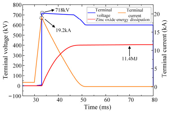
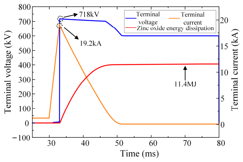
To evaluate the fault-energy handling capability of the zinc oxide varistor group in the absorption branch, the breaker current, terminal voltage, and absorbed energy are analyzed, as shown in Figure 5.
Figure 5.
Terminal current, terminal voltage, and energy absorption of each component with MOV operation.
As shown in Figure 5, a fault is applied at 30 ms, causing the current to increase rapidly from the normal operating level. The HVDC breaker is subsequently activated, and the fault current is commutated to the transfer branch. Owing to the system inductance, a transient overvoltage develops across the breaker, resulting in a rapid voltage rise.
Approximately 3 ms later, the voltage reaches the MOV residual level and conduction begins. At this instant, the peak current reaches 19.2 kA. Thereafter, the MOV absorbs the fault energy and the current gradually decays to zero at 51.7 ms. The overvoltage then returns to the steady-state level, indicating the completion of the fault-clearing process. The total absorbed energy of a single valve section is 11.4 MJ.
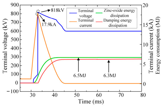
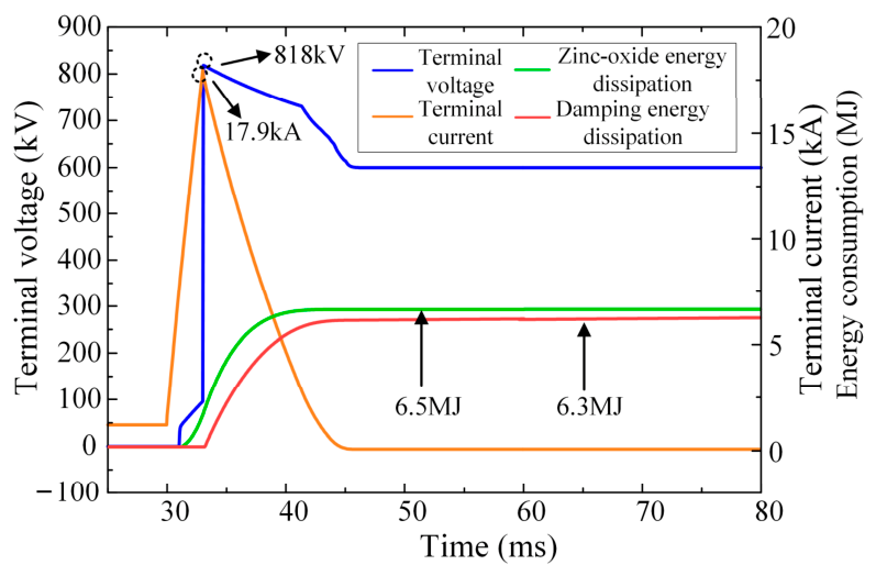
To investigate the coordinated energy-dissipation characteristics of the zinc oxide varistors and the damping module, Figure 6 shows the terminal current, terminal voltage, and the energy dissipated by each component under the combined energy-dissipation mode.
Figure 6.
Terminal current, terminal voltage, and energy dissipation of each component during the combined energy dissipation of zinc oxide varistor blocks and the damping module.
When a short-circuit fault occurs, the fault current is transferred to the transfer branch at 31 ms. At this moment, the damping module starts to operate, which not only limits the fault current amplitude but also dissipates part of the system energy. At 33 ms, the zinc oxide varistors begin to conduct and dissipate energy. At this stage, the terminal voltage reaches 818 kV, which is composed of the residual voltage of the zinc oxide varistors and the voltage across the damping resistor. Thereafter, the zinc oxide varistors and the damping module dissipate energy simultaneously. At 44.7 ms, the energy-dissipation process is completed. The energy absorbed by the zinc oxide varistor group in a single valve section is 6.3 MJ, while the total energy dissipated by the damping module is 6.5 MJ.
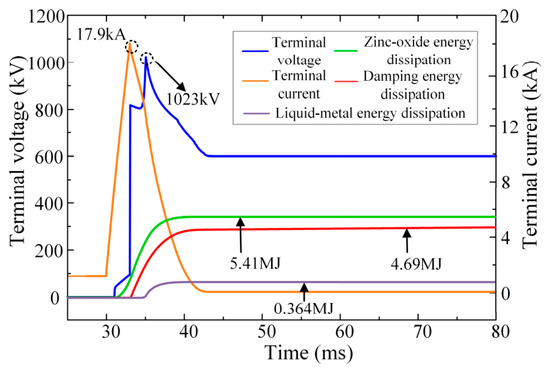
To further evaluate the performance of the composite absorption scheme, Figure 7 presents the transient responses of the liquid-metal unit, MOVs, and damping unit during fault clearing.
Figure 7.
Terminal current, terminal voltage, and energy dissipation of each component during composite energy dissipation.
As shown in Figure 7, a fault is applied at 30 ms, causing the current to increase rapidly. At 31 ms, the current is commutated to the transfer branch, where the damping unit begins to suppress the current and absorb part of the fault energy. After the absorption branch is inserted, the MOV voltage reaches its residual level at 33 ms, and the MOVs conduct first. During this period, the liquid metal remains in the pre-breakdown stage and behaves as a low-resistance conductor.
At 35.2 ms, arc formation occurs in the liquid-metal unit, and the liquid metal, MOVs, and damping unit jointly participate in fault-energy absorption. The peak breaker voltage reaches 1023 kV. The current decreases to zero at 42.4 ms, completing the fault-clearing process. The absorbed energy of a single MOV valve section is 4.69 MJ, while the liquid-metal unit and damping unit account for 0.364 MJ and 5.41 MJ, respectively.
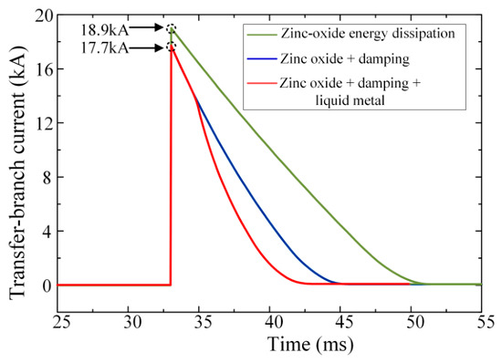
Figure 8 compares the energy-dissipation branch current under three different energy-dissipation modes. Compared with the other two modes, the composite energy-dissipation mode based on the liquid-metal module, zinc oxide varistors, and damping module completes the interruption process earlier. Therefore, the short-circuit current decreases more rapidly and reaches zero in a shorter time.
Figure 8.
Comparison of energy-dissipation branch currents under three energy-dissipation modes.
We list the key parameters of the three topologies and conduct a quantitative comparison. The peak current of the proposed composite topology is lower than the scheme with zinc oxide alone. Owing to the additional energy dissipation of liquid metal after arcing, the short-circuit current decays faster, and the current zero-crossing time is shortened to 42.4 ms, which is 9.3 ms and 2.3 ms earlier than Scheme 1 and Scheme 2, respectively. In the comparison curve in Scheme 1, all fault energy is borne by the zinc oxide arrester alone, which causes heavy thermal load on zinc oxide. After introducing the damping resistor in Scheme 2, the energy borne by zinc oxide is reduced by 44.7%. On this basis, the proposed topology further introduces liquid metal for auxiliary energy dissipation, cutting the energy absorbed by zinc oxide down to 4.69 MJ (only 41.1% of Scheme 1), effectively lowering the thermal stress of zinc oxide valve plates and prolonging the service life of arresters. Figure 8 also verifies that the proposed topology has the steepest current falling slope. The peak terminal voltage rises moderately with the increase in energy-consuming components. The composite scheme combining liquid-metal modules, zinc oxide varistors and damping resistors finishes the fault clearing process ahead of the other two designs, yielding a faster decay and earlier zero-crossing of the short-circuit current. The relevant data [13] are shown in Table 2.
Table 2.
Performance comparison of three energy-consuming topologies.
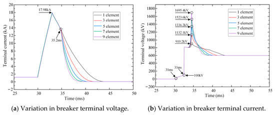
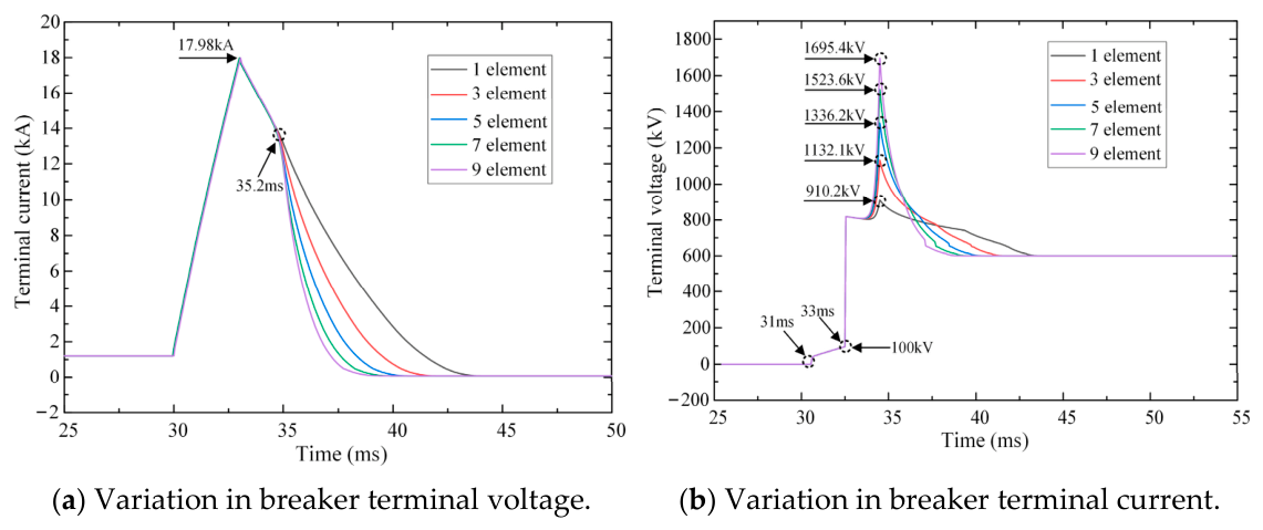
The influence of the number of series-connected liquid-metal elements on breaker performance is evaluated under a residual voltage coefficient of 1.2. Figure 9 presents the absorbed energy of the MOVs, liquid-metal units, and damping resistor, together with the corresponding breaker voltage and current, for one, three, five, seven, and nine series-connected liquid-metal elements in each valve section.
Figure 9.
Influence of the number of liquid-metal elements on fault-energy absorption.
As shown in Figure 9a, the damping resistor is activated at 31 ms, causing a slight increase in breaker voltage. At 33 ms, the MOVs begin to conduct and clamp the transient voltage at the residual level. Arc formation occurs in the liquid-metal units at 35.2 ms, leading to a further voltage rise because the liquid-metal units do not possess voltage-clamping capability.
Compared with the case without liquid-metal units, the peak breaker voltage increases by 90.2 kV, 312 kV, 516.2 kV, 703.6 kV, and 875.4 kV for one, three, five, seven, and nine series-connected units, respectively. These results indicate that excessive series connection significantly increases the breaker voltage. Therefore, the allowable number of liquid-metal units is constrained by the insulation requirements of the transfer-branch power electronic devices.
Figure 9b illustrates the corresponding current responses. Between 31 ms and 33 ms, the current is effectively limited by the damping resistor. After the absorption branch is inserted, the MOVs operate first, followed by arc initiation in the liquid-metal units at 35.2 ms. Increasing the number of liquid-metal units accelerates current decay and shortens the fault-clearing process. The reduction in clearing time reaches 1.1 ms, 2.9 ms, 4.4 ms, 5.3 ms, and 6.1 ms for one, three, five, seven, and nine units, respectively. However, additional units continue to improve interruption performance.
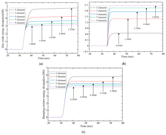
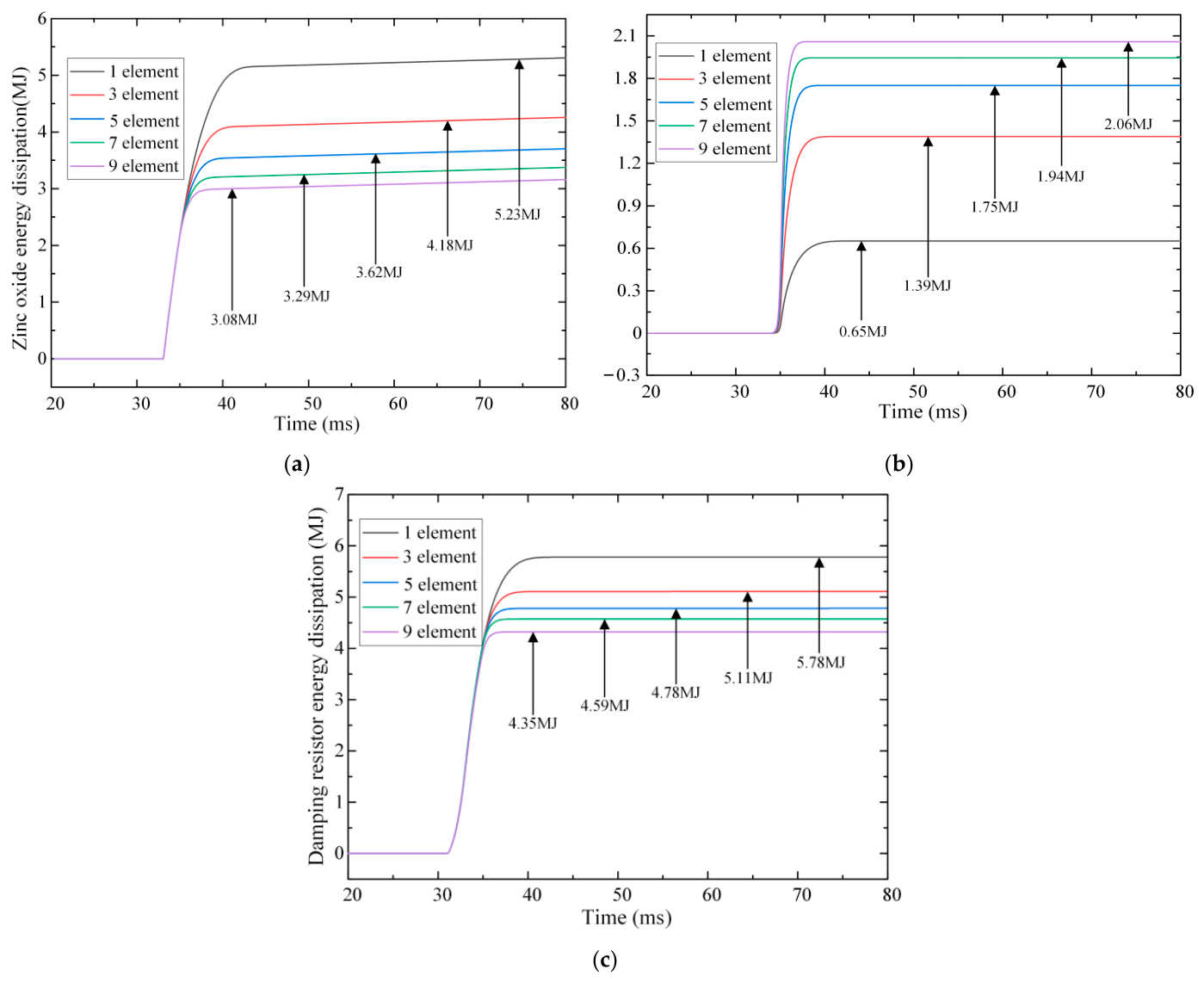
Figure 10 illustrates the influence of the number of liquid-metal units on the energy distribution of each component under a residual voltage coefficient of 1.2. Figure 10a,b present the absorbed energy of the MOVs and liquid-metal units in a single valve section, respectively. As the number of series-connected liquid-metal units increases, the absorbed energy of both components gradually decreases. This behavior is attributed to the increase in arc resistance introduced by additional liquid-metal units. Combined with the MOV resistance, the equivalent branch resistance becomes larger, accelerating current decay and reducing the total absorbed energy. The energy absorbed by the MOVs decreases from 5.23 MJ to 4.18 MJ, 3.62 MJ, 3.29 MJ, and 3.0 MJ as the number of liquid-metal units increases. Figure 10c shows the corresponding results for the damping resistor. A similar trend is observed, with the absorbed energy gradually decreasing as more liquid-metal units are connected in series.
Figure 10.
Influence of the number of liquid-metal elements on energy distribution among breaker components (k = 1.2). (a) Variation in zinc oxide energy dissipation per valve section. (b) Variation in liquid-metal energy dissipation per valve section. (c) Variation in total damping resistor energy dissipation.
Overall, the introduction of liquid-metal units effectively reduces the energy absorbed by the MOVs and damping resistor while shortening the fault-clearing process. However, further increasing the number of series-connected units lowers the energy utilization of each liquid-metal unit. Moreover, excessive insertion results in a higher breaker voltage, additional power electronic devices in each valve section, and increased insulation requirements.
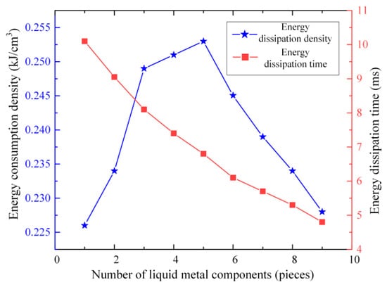
Figure 11 illustrates the effects of the number of liquid-metal units on clearing time and volumetric energy density. As the number of units increases, current decay becomes faster and the clearing time is reduced. The overall volumetric energy density first increases and then decreases, reaching its maximum value when five liquid-metal units are connected in series in each valve section.
Figure 11.
Influence of the number of liquid-metal elements on clearing time and volumetric energy density.
Based on the updated energy absorbed by the MOVs, the required number of valve blocks is determined. The volume of each liquid-metal unit is set to 1200 cm3. According to the residual voltage coefficient and energy requirement, the corresponding number of MOV blocks is calculated. The selected device is the Littelfuse QA22 series, with a maximum clamping voltage of 7.7 kV, an energy rating of 34.6 kJ, and dimensions of 71 mm × 34 mm, corresponding to a volume of approximately 171 cm3 per block.
Table 3 summarizes the volumetric energy density for different numbers of liquid-metal units. The maximum improvement of 24.6% is achieved with five series-connected units. However, further increasing the number of units raises the breaker voltage to 1336.2 kV, exceeding twice the rated value and resulting in stricter requirements for power electronic devices and system insulation.
Table 3.
Comparison of volumetric energy density for different numbers of liquid-metal elements.
Considering volumetric energy density, breaker voltage, and insulation constraints, three series-connected liquid-metal units provide the most balanced solution under a residual voltage coefficient of 1.2. In this case, the volumetric energy density reaches 0.248 kJ/cm3, representing a 22.2% improvement over the original configuration.
4.2. Performance Comparison Under Different MOV Residual Voltage Coefficients
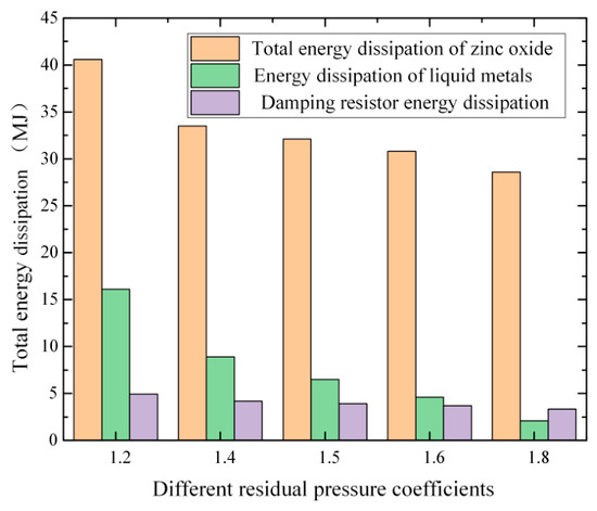
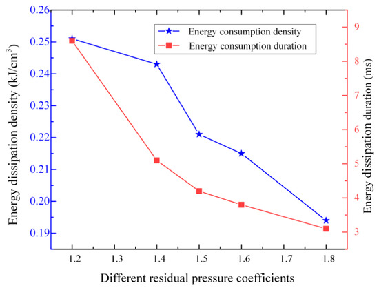
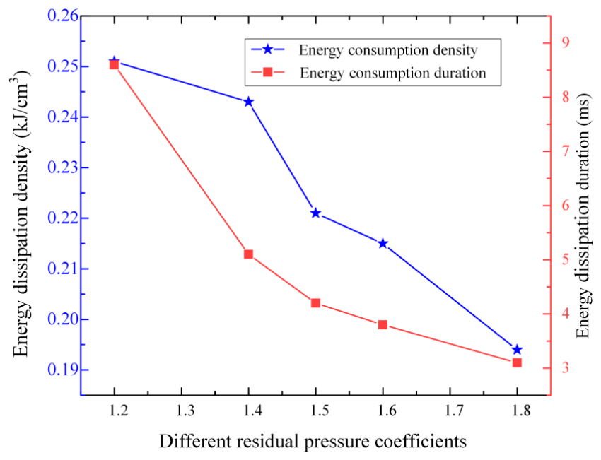
As shown in Figure 12, when two liquid-metal components are connected in series at residual pressure levels of 1.2, 1.4, 1.5, 1.6, and 1.8, the energy consumption of the liquid metal is 15.7 MJ, 8.7 MJ, 6.5 MJ, 4.8 MJ, and 2.3 MJ, respectively. It can be observed that as the residual pressure level increases, the dissipated energy of the liquid-metal components decreases. Figure 13 shows that the duration of circuit breaker energy consumption is 8.5 ms, 5.1 ms, 4.2 ms, 3.7 ms, and 3.2 ms. As the residual pressure level increases, the duration of energy consumption decreases. This trend is mainly attributed to the nearly unchanged branch current under different coefficient settings. As a result, the arc resistance of the liquid-metal units remains approximately constant, and only the operating duration varies. In contrast, increasing the residual voltage coefficient raises the equivalent resistance of the MOVs, thereby reducing the energy absorbed by the liquid-metal units.
Figure 12.
Energy absorption of MOVs and liquid-metal units under different residual voltage coefficients.
Figure 13.
Variation in clearing time and volumetric energy density under different residual voltage coefficients.
5. Discussion
This section comprehensively assesses the performance of the composite energy-dissipation topology, integrating gallium–indium–tin liquid metal, zinc oxide varistors and damping resistors, that is proposed in this paper. It summarizes its core technical merits, analyzes inherent engineering constraints, and outlines targeted future research directions based on the simulation results presented in preceding sections. In terms of technical superiority, the three-way coordinated energy-absorption structure outperforms conventional single MOV schemes and dual MOV-damping configurations widely deployed in existing hybrid HVDC circuit breakers. Throughout the entire fault interruption cycle, multiple functional units jointly absorb transient fault energy. Simulation outcomes demonstrate that with an identical residual voltage coefficient, the proposed topology drastically alleviates the energy burden on zinc oxide varistor stacks, reduces the quantity of parallel varistor plates, and substantially downsizes the overall footprint of the energy-dissipation branch. These performance gains provide a solid theoretical basis for developing compact, cost-effective 600 kV hybrid DC breakers for offshore island power systems and cross-border HVDC interconnections. However, the topology faces prominent obstacles restricting its large-scale field application, primarily stemming from the material properties of the Ga-In-Sn eutectic alloy. The Galinstan liquid metal utilized herein has a solidification temperature of −19 °C. Persistent ambient temperatures below this threshold will fully solidify the alloy, eliminating its fluidity and self-magnetically pinched arc generation capacity. Without viable arc channels to dissipate short-circuit energy, the composite energy-dissipation unit ceases to function in cold regions. Furthermore, long-term service in subsea HVDC environments exposes the device to constant hydraulic pressure, salt mist corrosion and high humidity, which accelerate aging of the liquid-metal cavity seals, erode internal metallic electrodes, and gradually impair the long-term stability of MOV components. These two critical bottlenecks narrow the applicable operation scenarios of the novel breaker.
To address the above strengths and limitations, a systematic research roadmap is proposed for subsequent investigations. The foremost task is to construct a small-scale prototype test platform and manufacture a full integrated prototype of the liquid-metal–MOV composite energy-dissipation branch. Comprehensive fault interruption tests under real high-current fault conditions will be conducted, with time-domain waveforms of branch voltage, fault current and energy dissipation of each independent component recorded synchronously. Collected experimental measurements will be employed to calibrate and refine the time-varying nonlinear Mayr arc model established via PSCAD/EMTDC. Guided by test data, structural upgrades will be carried out, and low-freezing-point modified Ga-In-Sn alloy formulas will be developed to resolve the low-temperature failure issue. The integrated approaches of prototype validation, material modification and structural refinement will collectively improve the device’s environmental tolerance and operational reliability, facilitating the practical engineering implementation of the presented topological solution in island microgrids and cross-border HVDC transmission projects.
6. Conclusions
The operating mechanism of Ga–In–Sn is clarified. The results indicate that Lorentz-force-driven self-constriction leads to arc initiation, and the arc evolution exhibits distinct stage-dependent characteristics. A hybrid HVDC circuit breaker incorporating liquid-metal units, MOVs, and damping resistors is proposed. A PSCAD/EMTDC model is developed to evaluate the transient behavior and energy allocation of each component during fault interruption. Under a fixed limiting-voltage coefficient, increasing the number of series-connected liquid-metal units accelerates current decay and shortens the fault-clearing process. With three units connected in series, the volumetric energy density reaches 0.248 kJ/cm3, representing a 22.2% improvement over the original configuration. As the MOV residual voltage coefficient increases, the reduction in clearing time becomes less significant, while the overall volumetric energy density gradually decreases.
Author Contributions
Y.M.: Conceptualization Investigation, Visualization, Software, Methodology, Writing—original draft. Z.L. (Zhitan Liu): Visualization, Resources, Methodology, Investigation. Z.G.: Resources, Investigation, Conceptualization, Data curation. S.Y.: Methodology, Investigation, Software, Formal analysis. K.Z.: Resources, Methodology, Conceptualization. Z.L. (Zheng Li): Formal analysis, Writing—Review and editing, Data collection. G.W.: Conceptualization, Resources, Formal analysis. A.W.: Investigation, Data curation. Y.C.: Formal analysis; Software. Y.D.: Visualization, Data curation, Conceptualization. G.G.: Visualization, Supervision, Conceptualization. L.Q.: Software, Resources, Investigation. All authors have read and agreed to the published version of the manuscript.
Funding
This work was supported by the National Natural Science Foundation of China (U1966602); the Jiangsu Funding Program for Excellent Postdoctoral Talent (2025ZB513); the National Key Research and Development Program (2024YFB2606300); and the Innovation Research Group Project of the Natural Science Foundation of Sichuan (2024NSFTD0009).
Data Availability Statement
The original contributions presented in the study are included in the article.
Conflicts of Interest
Yaguang Ma, Zhitan Liu, Zongbao Gao, Sheng Yang, Ke Zhuang, Yanyu Chen, Yuehong Dong and Lei Qiao were employed by China Energy Science and Technology Research Institute Co., Ltd. The remaining authors declare that there are no commercial or financial relationships that could be interpreted as potential conflicts of interest in this research.
Appendix A
For ease of reference, Table A1 summarizes all of the key symbols, parameters, and indices used in the methodological derivations of this subsection. Each symbol is listed together with its physical meaning and its corresponding SI unit. Although every variable is also defined at its first occurrence in the text, this consolidated nomenclature table is provided to help readers quickly locate the definitions and units without having to search through the narrative.
Table A1.
Nomenclature of key symbols.
References
- Pan, R.; Yang, Y.; Yang, J.; Liu, D. Enhanced grid forming control for MMC-HVDC with DC power and voltage regulation. Electr. Power Syst. Res. 2024, 229, 110166. [Google Scholar] [CrossRef] [Scilit]
- Li, Z.; Wu, Q.; Li, H.; Nie, C.; Tan, J. Distributed low-carbon economic dispatch of integrated power and transportation system. Appl. Energy 2024, 353, 122134. [Google Scholar] [CrossRef] [Scilit]
- He, Y.; Xiang, W.; Meng, P.; Wen, J. Investigation on grid-following and grid-forming control schemes of cascaded hybrid converter for wind power integrated with weak grids. Int. J. Electr. Power Energy Syst. 2024, 155, 109524. [Google Scholar] [CrossRef] [Scilit]
- Wang, D.; Zhao, J.; Wang, C.; Zhu, X.; Zhou, Z.; Li, W.; Jia, Y.; Li, Z.; Wu, S.; Meng, J. An adaptive linear active disturbance rejection control method for HVDC transmission system. Energy Rep. 2023, 9, 3282–3289. [Google Scholar] [CrossRef] [Scilit]
- Hassanpoor, A.; Häfner, J.; Jacobson, B. Technical assessment of load commutation switch in hybrid HVDC breaker. IEEE Trans. Power Electron. 2014, 30, 5393–5400. [Google Scholar] [CrossRef] [Scilit]
- Meyer, J.M.; Rufer, A. A DC Hybrid Circuit Breaker with Ultra-Fast Contact Opening and Integrated Gate-Commutated Thyristors (IGCTs). IEEE Trans. Power Deliv. 2000, 21, 646–651. [Google Scholar]
- Veilleux, E.; Ooi, B.T. Multiterminal HVDC with thyristor power-flow controller. IEEE Trans. Power Deliv. 2012, 27, 1205–1212. [Google Scholar] [CrossRef] [Scilit]
- Granizo Arrabé, R.; Platero, C.A.; Álvarez Gómez, F.; Rebollo López, E. New differential protection method for multiterminal HVDC cable networks. Energies 2018, 11, 3387. [Google Scholar] [CrossRef] [Scilit]
- Li, X.; Huang, R.; Wang, X.; Liu, G.; Jia, Z.; Wang, L. A simple optimized design of an electrode to conduct flash sintering at room temperature and low onset electric field. Scr. Mater. 2020, 186, 158–162. [Google Scholar] [CrossRef] [Scilit]
- Liu, J.; Li, X.; Wang, X.; Huang, R.; Jia, Z. Alternating current field flash sintering 99% relative density ZnO ceramics at room temperature. Scr. Mater. 2020, 176, 28–31. [Google Scholar] [CrossRef] [Scilit]
- Benasla, M.; Allaoui, T.; Brahami, M.; Denaï, M.; Sood, V.K. HVDC links between North Africa and Europe: Impacts and benefits on the dynamic performance of the European system. Renew. Sustain. Energy Rev. 2018, 82, 3981–3991. [Google Scholar] [CrossRef] [Scilit]
- Fotopoulou, M.; Pediaditis, P.; Skopetou, N.; Rakopoulos, D.; Christopoulos, S.; Kartalidis, A. A review of the energy storage systems of non-interconnected European islands. Sustainability 2024, 16, 1572. [Google Scholar] [CrossRef] [Scilit]
- Yu, J.; Xu, Z.; Zhang, Z.; Song, Y. Hybrid HVDC circuit breakers with an energy absorption branch of a parallel arrester structure. High Volt. 2022, 7, 12138. [Google Scholar] [CrossRef] [Scilit]
- Groppi, D.; Pfeifer, A.; Garcia, D.A.; Krajačić, G.; Duić, N. A review on energy storage and demand side management solutions in smart energy islands. Renew. Sustain. Energy Rev. 2021, 135, 110183. [Google Scholar] [CrossRef] [Scilit]
- Wu, H.; Li, X.; Zhang, M.; Stade, D.; Schau, H. Analysis of a Liquid Metal Current Limiter. IEEE Trans. Compon. Packag. Technol. 2009, 32, 572–577. [Google Scholar] [CrossRef] [Scilit]
- Ma, Y.; Gao, G.; Xiang, Y.; Dong, K.; Yan, L.; Yang, Z.; Wu, G. Simulation Study on Transient Process of Liquid Metal Current Limiter. In 2023 Panda Forum on Power and Energy (PandaFPE); IEEE: New York, NY, USA, 2023; pp. 183–187. [Google Scholar]
- Zienicke, E.; Li, B.-W.; Thess, A.; Kräzschmar, A.; Terhoeven, P. Theoretical and numerical stability analysis of the liquid metal pinch using the shallow water approximation. J. Therm. Sci. 2008, 17, 261–266. [Google Scholar] [CrossRef] [Scilit]
- Wang, J.-W.; Wang, X.-L.; Sun, Y.-C.; Huang, Y.-H.; Chen, X.-M.; Wu, X.-Z.; Li, N.; Kang, J.-W.; Jing, T.; Huang, T.-Y.; et al. Prediction of intrusive gas pores caused by resin burning in sand core for iron castings. China Foundry 2025, 22, 23–32. [Google Scholar]
- Niu, C.; Wang, B.; He, H.; Wu, Y.; Rong, M.; Li, J.; Wang, L.; Zhao, P. A Novel Liquid Metal Fault Current Limiter Based on Active Trigger Method. IEEE Trans. Power Deliv. 2020, 36, 3619–3628. [Google Scholar] [CrossRef] [Scilit]
- Staudt, V.; Bartelt, R.; Heising, C. Short-circuit protection issues in DC ship grids. In 2013 IEEE Electric Ship Technologies Symposium (ESTS); IEEE: New York, NY, USA, 2013; pp. 475–479. [Google Scholar]
- He, H.; Rong, M.; Wu, Y.; Yang, F.; Liu, Y.; Man, J.; Luo, J.; Shi, Q. Experimental Research and Analysis of a Novel Liquid Metal Fault Current Limiter. IEEE Trans. Power Deliv. 2013, 28, 2566–2573. [Google Scholar] [CrossRef] [Scilit]
- Yang, Z.; He, H.; Yang, F.; Wu, Y.; Rong, M.; Zhao, P.; Lv, S.; Wan, Q. A novel topology of a liquid metal current limiter for MVDC network applications. IEEE Trans. Power Deliv. 2019, 34, 661–670. [Google Scholar] [CrossRef] [Scilit]
- Wang, B.; Niu, C.; He, H.; Wu, Y.; Rong, M.; Wang, L.; Li, J. Development of a Hybrid Fault Current Limiter Using Liquid Metal for Large Capacity MVDC Power Systems. IEEE Trans. Ind. Electron. 2021, 69, 5050–5059. [Google Scholar] [CrossRef] [Scilit]
- Gao, G.; Wang, A.; Ma, Y.; You, B.; Peng, W.; Yang, Z.; Wu, G. Analysis of shrinkage characteristics of GaInSn liquid metal in pre-arc process. Plasma Sci. Technol. 2025, 27, 055501. [Google Scholar] [CrossRef] [Scilit]
- Ju, X.; Sun, H.; Yang, Z.; Zhang, J. Investigation on the arc ignition characteristics and energy absorption of liquid metal current limiter based on self-pinch effect. Plasma Sci. Technol. 2016, 18, 531–537. [Google Scholar] [CrossRef] [Scilit]
- van Sint Annaland, M.; Deen, N.G.; Kuipers, J.A.M. Numerical simulation of gas bubbles behaviour using a three-dimensional volume of fluid method. Chem. Eng. Sci. 2005, 60, 2999–3011. [Google Scholar] [CrossRef] [Scilit]
- Ma, Y.; Gao, G.; Xiang, Y.; Peng, W.; Dong, K.; Qian, P.; You, B.; Yang, Z.; Wei, W.; Wu, G. Research on the energy consumption mechanism and characteristics of the gallium indium tin liquid metal arcing process. Plasma Sci. Technol. 2023, 25, 095502. [Google Scholar] [CrossRef] [Scilit]
- Gao, G.; Ma, Y.; Dong, K.; Xiang, Y.; Li, Z.; Wang, X.; Wang, A.; You, B.; Yang, Z.; Wei, W.; et al. The energy dissipation topology and characteristics of GaInSn liquid metal and ZnO resistors based on high-voltage DC circuit breakers. Phys. Scr. 2023, 99, 015605. [Google Scholar] [CrossRef] [Scilit]
- Anaya, O.; Acha Lara, E. Modeling and Analysis of Custom Power Systems by PSCAD/EMTDC. IEEE Trans. Power Deliv. 2002, 17, 266–272. [Google Scholar] [CrossRef] [Scilit]
- Schavemaker, P.H.; Van der Slui, L. An improved Mayr-type arc model based on current-zero measurements [circuit breakers]. IEEE Trans. Power Deliv. 2000, 15, 580–584. [Google Scholar] [CrossRef] [Scilit]
- Liu, X.; Huang, X.; Cao, Q. Simulation and experimental analysis of DC arc characteristics in different gas conditions. IEEE Trans. Plasma Sci. 2021, 49, 1062–1071. [Google Scholar] [CrossRef] [Scilit]

Disclaimer/Publisher’s Note: The statements, opinions and data contained in all publications are solely those of the individual author(s) and contributor(s) and not of MDPI and/or the editor(s). MDPI and/or the editor(s) disclaim responsibility for any injury to people or property resulting from any ideas, methods, instructions or products referred to in the content. |
© 2026 by the authors. Licensee MDPI, Basel, Switzerland. This article is an open access article distributed under the terms and conditions of the Creative Commons Attribution (CC BY) license.