


Abstract
This study develops an efficient finite formulation to predict thermoelastic nonlinear bending of sandwich frames with a functionally graded porous (FGP) core and homogeneous face sheets. The formulation incorporates temperature-dependent properties and various thickness-graded porosity patterns, utilizing third-order shear deformation theory and von Kármán nonlinear relations. To enhance computational efficiency, the model employs shear rotation as the independent variable rather than traditional cross-sectional rotation. Nonlinear equations are solved using the Newton–Raphson method. Results demonstrate a significant impact of thermal and porosity effects on the nonlinear response, and the frame deformation is significantly increased when increasing the porosity coefficient and temperature. Detailed analysis is presented to show the effects of porosity coefficients, distribution patterns, and temperature increments on the frame nonlinear behavior.
1. Introduction
Functionally graded porous (FGP) materials have emerged as a promising solution for modern lightweight structures, offering the ability to customize thermoelastic properties by tailoring internal pore distributions. Recently, these materials have been integrated into frames—the most prevalent load-bearing systems—to minimize total weight and enhance thermal resistance [1]. From an engineering perspective, frames typically consist of slender members that undergo significant deformation under load. Consequently, nonlinear analysis of FGP frames under thermomechanical loading is essential for the robust design of these structures.
Various theories can be employed to model frame deformation, among which Third-order Shear Deformation Theory (TSDT) is often preferred as it eliminates the need for shear correction factors. Utilizing TSDT within a finite element framework—combined with a strategic selection of independent variables—effectively mitigates the shear-locking phenomenon, a common deficiency in first-order theory-based formulations [2]. Regarding the FGP beam and frame structures, most current studies focus on single beams or consider temperature-independent material properties [3,4].
Despite the growing interest in porous sandwich beam and frame structures, studies addressing geometrically nonlinear responses of porous sandwich frames with temperature-dependent material properties remain very limited. To fill this gap, this paper presents an efficient finite element formulation for predicting the nonlinear bending responses of porous sandwich frames, accounting for thermal dependence of material properties and different porosity distribution patterns. Based on a third-order shear deformation theory and von Kármán nonlinear relationship, the formulation is derived using transverse shear rotation as an independent variable. The resulting discretized nonlinear equilibrium equation is established and solved by the Newton–Raphson iterative procedure. A parametric study is conducted to show the efficiency of the proposed formulation and to highlight the influence of key governing factors on the nonlinear behavior of the frames.
2. Mathematical Formulation
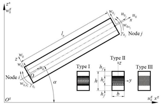
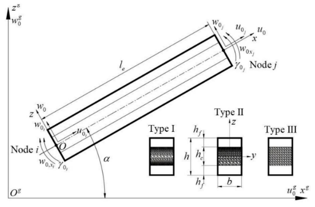
Figure 1 shows a beam element with length L, width b, and thickness h in both local and global coordinate systems. The element consists of a porous core sandwiched between two face sheets. Three porosity distribution patterns in the thickness, namely symmetric, asymmetric, and uniform, are considered. The material properties are considered to be temperature-dependent, and a typical property varies with temperature T according to [1,5]
where T = T0 + ΔT with T0 = 300° K is the reference temperature; P−1, P0, P1, P2, and P3 are material-specific temperature coefficients.
Figure 1.
Geometry and kinematics of an FGP beam element.
The effective Young’s modulus (E), thermal expansion coefficient (λ), and shear modulus (G) of the porous core are dependent on the three porous distribution patterns as follows [1]:
Type I: Symmetric distribution
Type II: Asymmetric distribution
Type III: Uniform distribution
Both the top and bottom face sheets consist of pure isotropic materials with properties determined by the Young modulus and shear modulus
For a uniform porosity distribution, the core properties are constant through the thickness, and the coefficient a in Equation (4) is given by
According to the third-order shear deformation theory [6], the displacement components in the x and z directions of a point within the element are expressed as follows
The variables u0 and w0 denote the axial and transverse displacements of a point on the mid-plane, respectively, while θ0 represents the cross-sectional rotation. The subscript comma in Equation (7) and below indicates the partial derivative, e.g., (⋅),x = ∂(⋅)/∂x. Following Shi and Lam [2], the finite element formulation is more efficient by adopting the following transverse shear rotation as an independent variable
Using the transverse shear rotation γ0, one can recast the displacements in Equation (7) in the form
Let and be the global displacements in the xg-, zg-directions, and the global transverse shear deformation, respectively. The local displacements and rotation are related to the global ones by
with
Equation (9) gives the strains in term of von Kármán nonlinear relation in the form
where is the membrane strain.
Based on Hooke’s law, the constitutive relations for the stresses σxx and τxz are given by
where E(z,T) and G(z,T) are defined by Equations (2)–(4).
The elastic strain energy of the sandwich beam reads
where is the volume of the beam element.
Using Equations (12) and (13), one can write the strain energy in Equation (14) in the form
with Ii (i = 1,…,5) being the rigidities, defined as
where .
The thermal strain energy due to temperature rise is given by [5]
where NT is the thermal resultant, which can be expressed as
with as the thermal expansion coefficient defined in Equations (2)–(4).
The work done by the external loads is given by
where q(x) denotes the distributed load, with a concentrated load treated as a special case.
The nonlinear equilibrium equations are derived from the principle of virtual work as follows.
where nELE is the total number of elements. Equation (20) leads to a system of nonlinear differential equations with unknowns u0, w0, and γ0. Due to its complexity, the finite element method is used herein to construct the discretized equilibrium equations and to predict the bending response.
3. Solution Method
A two-node beam element is considered. The local vector of degrees of freedom (d.o.f.) for the element, Δe, contains the displacements and shear rotations at the two nodes with the form
in which
are the vectors, the local axial displacements and the shear rotations at the nodes as depicted in Figure 1. The superscript “T” in the above equation and below indicates the transpose of vector or a matrix. The displacements and shear deformation inside the element are interpolated as [7]
with h as the matrix of linear functions and hw as the matrix of cubic polynomials, and they have the following forms [7]
Taking the derivative of Equation (23) with respect to x, we obtain
The axial strain in Equation (12) and the interpolation (24), (25) may cause membrane locking in the finite element. To overcome this, the membrane strain ε0 is replaced by an effective strain, as proposed in [7]
From Equations (24) and (25), one can write Equation (26) in the form
where
With the interpolations, the strain energy in Equation (15) can be expressed in matrix form as
where
and
Therefore,
The work done by external forces, Equation (19), can be rewritten as follows
The internal force vector is obtained by differentiating the strain energy Equation (32) with respect to the nodal displacements as follows
in which
The external forces element vector, , can also be expressed in matrix form as follows
The local vectors of d.o.f., as well as the internal and external force vectors, are connected to their global counterparts via a transformation matrix transpose; for example
with Tt being the transformation matrix of size (8 × 8), and its form can be derived from Equation (11).
By assembling the derived element vectors and over all elements, the equilibrium equation can be constructed in the following form [8].
Here, represents the global vector of d.o.f., while , and are the global vectors of external force, internal force, and residual force, respectively.
The global tangent stiffness matrix is derived from the variation in the global internal force, as expressed below
The global internal force vector and the tangent stiffness matrix are assembled from their respective element-level contributions according to the relationships defined in Equations (10) and (37), as follows
Consequently, the element tangent stiffness matrix may be expressed in matrix form as follows
The submatrices in the above equation are defined as follows
The global tangent stiffness is then employed in the following linearized equilibrium equation
The nonlinear system is solved for the global d.o.f. vector using the Newton–Raphson method in [8]. The convergence criterion is given by and ϵtol is the prescribed tolerance, set to 10−4 in this work.
4. Numerical Investigation
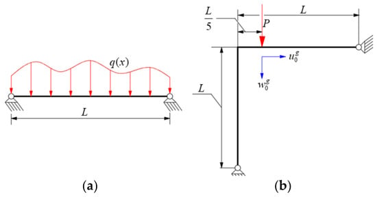
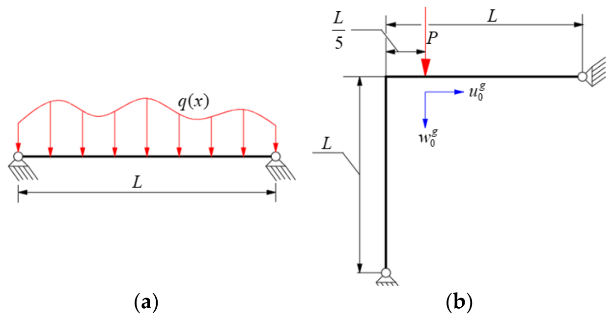
Consider an FGP sandwich beam and an FGP sandwich frame made from SUS304 steel with pinned–pinned (PP) boundary conditions as illustrated in Figure 2. The temperature-dependent coefficients Pi (i = −1, 0, 1, 2, 3) of the elastic modulus E, Poisson’s ratio ν, and the thermal expansion coefficient λ for SUS304 are given in [5]. The geometric data are L = 1 m, h = b = 0.05 m, and hc/hf = 8. For convenience of discussion, the dimensionless parameters for the applied load and transverse displacement are defined as
Figure 2.
Beam and frame used in analysis. (a) Simply supported beam under distributed load q(x); (b) asymmetric frame under a concentrated load P. Red arrows indicate the applied loads, while blue arrows indicate the displacement components.
No studies on FGP sandwich frame problems considering thermal effects have been reported. Therefore, the present model is validated through comparison for special cases, especially the nonlinear bending response being compared with the result of Ref. [9]. Table 1 demonstrates the accuracy and convergence of the proposed element in predicting the dimensionless midspan deflection of an FGP beam under uniformly distributed load (UDL) and sinusoidally distributed load (SDL), using the above geometric parameters. For consistency, identical boundary conditions, material properties, and normalization are adopted. The parameters E1 = 200/(1 − v2), G1 = 100/(1 + v1), and q0 = 50 × 103 N/m are used. The error in Table 1 is defined as follows
where and are the dimensionless deflections from the present model and Ref. [9], respectively.
Table 1.
Accuracy and convergence of for a PP FGP beam under different distributed loads.
Table 1 confirms the good accuracy (Er < 2.4%) and rapid convergence (nELE ≥ 4) of the derived formulation. The deflection increases with e0, indicating a reduction in stiffness. Moreover, UDL yields larger deflections than SDL, which is consistent with expected mechanical behavior and confirms the model.
Numerical Results
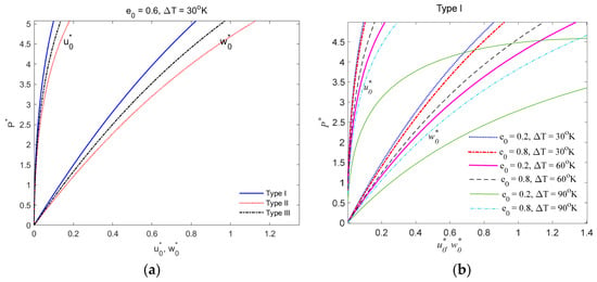
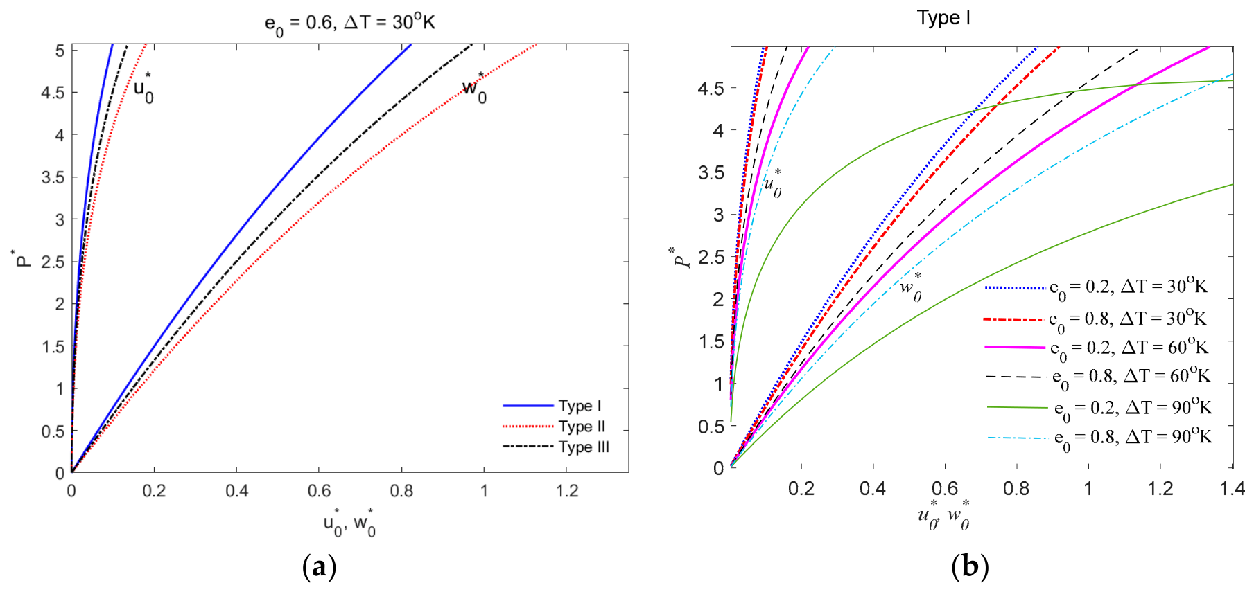
The nonlinear bending response of the FGP frame in thermal environment under a concentrated load P, as shown in Figure 2b, is analyzed and the results are depicted in Figure 3. Figure 3a shows the importance of the porosity distribution patterns on the nonlinear response, where the type I distribution yields the lowest displacements, while the type II gives the highest ones. One can conclude from Figure 3b that both the temperature and porosity coefficient significantly contribute to the deformation of the sandwich porous frames, and the increase in the coefficient e0 or same temperature rise ΔT amplifies the displacements. The amplification of the displacements becomes more significant by increasing both the temperature and porosity coefficient. A careful examination of Figure 3b shows that the effect of the temperature is more significant than that of the porosity coefficient.
Figure 3.
The nonlinear response of the FGP sandwich frame under thermomechanical loading with PP condition. (a) Effect of porosity distribution pattern; (b) effect of porosity and temperature variation.
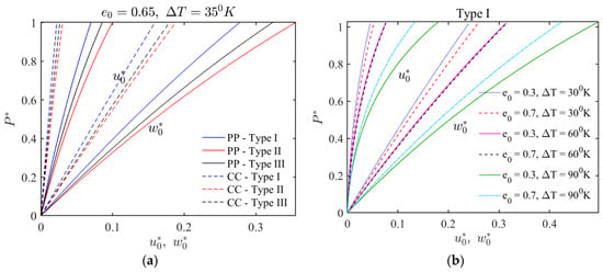
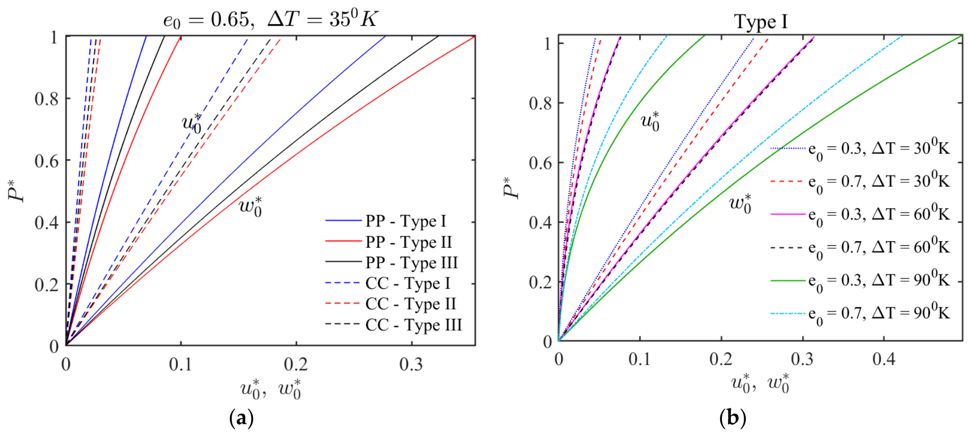
Figure 4 shows the effect of boundary conditions on the nonlinear thermomechanical behavior of the FGP frame. The results indicate that the clamp–clamp (CC) frame is stiffer than the PP frame. As a result, the CC frame undergoes smaller displacements under the same loading conditions.
Figure 4.
The nonlinear response of the FGP sandwich frame under thermomechanical loading with different boundary conditions. (a) Effect of porosity distribution pattern for PP and CC boundary conditions; (b) effect of porosity coefficient and temperature variation for type I porous distribution pattern for CC.
5. Conclusions
An efficient finite beam formulation for predicting the thermoelastic nonlinear bending of sandwich frames with an FGP core has been presented. The formulation incorporates temperature-dependent properties; graded porosity distributions are derived based on the third-order shear deformation theory and von Kármán nonlinearity. By adopting shear rotation as an independent variable, computational efficiency is improved, and the nonlinear problem is solved using the Newton–Raphson method. The results demonstrate the efficiency of the formulation and the strong impact of the temperature and porosity on the nonlinear structural response. The deformation of the frames is significantly increased when increasing both the porosity coefficient and temperature.
Author Contributions
Writing-original draft, investigation, formal analysis, T.T.P.; methodology, conceptualization, supervision, D.K.N.; validation, writing-review and editing, C.I.L. All authors have read and agreed to the published version of the manuscript.
Funding
This research received no external funding.
Institutional Review Board Statement
Not applicable.
Informed Consent Statement
Not applicable.
Data Availability Statement
The original contributions presented in this study are included in the article. Further inquiries can be directed to the corresponding author.
Conflicts of Interest
The authors declare no conflicts of interest.
References
- Chen, D.; Kitipornchai, S.; Yang, J. Nonlinear free vibration of shear deformable sandwich beam with a functionally graded porous core. Compos. Struct. 2016, 163, 311–325. [Google Scholar]
- Shi, G.; Lam, K.Y.; Tay, T.E. On efficient finite element modeling of composite beams and plates using higher-order theories and an accurate composite beam element. Compos. Struct. 1998, 41, 159–165. [Google Scholar] [CrossRef] [Scilit]
- Chen, D.; Yang, J.; Kitipornchai, S. Free and forced vibrations of shear deformable functionally graded porous beams. Int. J. Mech. Sci. 2016, 108, 14–22. [Google Scholar] [CrossRef] [Scilit]
- Wattanasakulpong, N.; Ungbhakorn, V. Linear and nonlinear vibration analysis of elastically restrained ends FGM beams with porosities. Aerosp. Sci. Technol. 2014, 32, 111–120. [Google Scholar] [CrossRef] [Scilit]
- Kim, Y.W. Temperature dependent vibration analysis of functionally graded rectangular plates. J. Sound Vib. 2005, 284, 531–549. [Google Scholar] [CrossRef] [Scilit]
- Reddy, J.N. A simple higher-order theory for laminated composite plates. J. Appl. Mech. 1984, 54, 745–752. [Google Scholar] [CrossRef] [Scilit]
- Crisfield, M.A. Nonlinear Finite Element Analysis of Solids and Structures; Wiley: New York, NY, USA, 1991. [Google Scholar]
- Krenk, S. Non-Linear Modeling and Analysis of Solids and Structures; Cambridge University Press: Cambridge, UK, 2009. [Google Scholar]
- Srikarun, B.; Songsuwan, W.; Wattanasakulpong, N. Linear and nonlinear static bending of sandwich beams with functionally graded porous core under different distributed loads. Compos. Struct. 2021, 276, 114538. [Google Scholar] [CrossRef] [Scilit]

Disclaimer/Publisher’s Note: The statements, opinions and data contained in all publications are solely those of the individual author(s) and contributor(s) and not of MDPI and/or the editor(s). MDPI and/or the editor(s) disclaim responsibility for any injury to people or property resulting from any ideas, methods, instructions or products referred to in the content. |
© 2026 by the authors. Licensee MDPI, Basel, Switzerland. This article is an open access article distributed under the terms and conditions of the Creative Commons Attribution (CC BY) license.