


Abstract
Concrete cover quality around reinforcing bars affects steel–concrete bond, as casting-induced voids and discontinuities may disturb the interface. This study examines the influence of transverse rib orientation on defect formation in self-compacting concrete cover under different bond conditions. Deep-beam elements with centrally embedded B500SP ribbed bars were cast from a single point, considering rib orientations of 0°, 45° and 90° relative to the formwork bottom. X-ray computed tomography was used to assess void distribution near the rebar. The results show that rib orientation affected the spatial arrangement of defects, including bleeding-related voids, settlement discontinuities and isolated large pores.
1. Introduction
Proper interaction between concrete and reinforcement is one of the fundamental prerequisites for the safe performance of reinforced concrete elements. The transfer of forces between the reinforcing bar and the surrounding concrete depends not only on the mechanical properties of both materials, but also on the quality of the steel–concrete interface. Within this zone, adhesion, friction, and mechanical interlocking between the bar and the concrete develop; therefore, any local discontinuities, voids, or weaknesses in the concrete structure may directly affect bond strength and, consequently, the load-bearing capacity, cracking behaviour, and durability of reinforced concrete structures.
Prior to setting of the concrete mix, segregation-related phenomena may occur, primarily plastic settlement and bleeding [1]. These processes lead to the local migration of water and fine particles of the mix, as well as to the formation of discontinuities in the vicinity of horizontally placed reinforcing bars. Particularly unfavourable conditions may develop beneath the underside of the bar, where accumulated air voids or spaces left by water released during bleeding reduce the actual contact area between the steel and the concrete. The quality of the steel–concrete contact zone is not uniform throughout the cross-section of the element. As the depth of fresh concrete beneath the bar increases, the effects associated with mix settlement and bleeding become more pronounced, which may lead to a deterioration of the bond conditions for bars located in the upper parts of the element [2,3]. This phenomenon is reflected in design standards [4,5] in which the unfavourable position of the bar during concreting is accounted for, among other measures, by increasing the required anchorage length.
The quality of this zone can be assessed using both direct and indirect methods, including, among others, analysis of the surface after specimen splitting [6], optical microscopy [7,8,9], and scanning electron microscopy [10] and its derivative backscattered electron imaging technique [11,12,13,14] which require the preparation of sections perpendicular to the bar axis. These methods enable the steel–concrete interface (SCI) to be characterised with a high degree of accuracy and precision. However, the preparation of specimens for such analyses is destructive and may itself cause damage, potentially leading to distorted results. A complete three-dimensional image of the SCI can be obtained using non-destructive radiation-based techniques, namely X-ray computed tomography (X-ray CT) [15,16,17,18,19] and neutron tomography [20,21]. X-ray CT enables the analysis of pore and void distribution, as well as local density variations in the vicinity of reinforcing bars. This allows the observed structural defects to be correlated more accurately with concreting conditions and with the results of bond strength tests.
This study analyses the quality of the steel–concrete interface for different configurations of horizontally placed reinforcing bars. Various orientations of the transverse ribs relative to the bottom surface of the formwork were considered, thereby accounting for their position relative to the direction of potential plastic settlement of the concrete mix and water migration during bleeding. This approach enables an assessment of whether the local geometry of the bar surface affects the formation of discontinuities in the SCI beneath horizontally placed reinforcement.
2. Materials and Methods
The study used a self-compacting concrete (SCC) mix based on Portland cement with the addition of fly ash. Two gravel fractions, 2–8 mm and 8–16 mm, were used as coarse aggregate, whereas natural sand with a fraction of 0–2 mm was used as fine aggregate. The required flowability of the mix was achieved using a polycarboxylate ether-based superplasticizer and a plasticizer, added in varying amounts. The composition of the SCC mix used in the experimental programme is presented in Table 1. The concrete mix was designed and supplied by a ready-mixed concrete producer in Poland.
Table 1.
Self-compacting concrete mix composition.
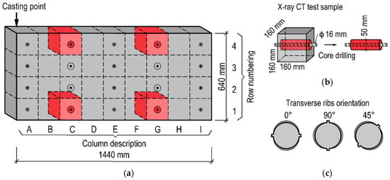
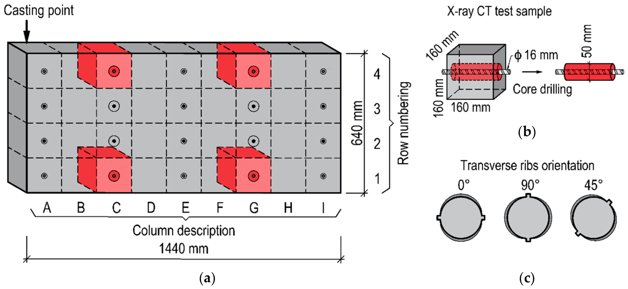
The influence of transverse rib orientation in reinforcing bars on the formation of defects within the concrete cover was assessed using core specimens extracted from larger deep-beam elements. The designed deep-beam element had dimensions of 1440 × 640 × 160 mm (length × height × thickness), as shown in Figure 1a, and was cast from a single casting point. The dimensions of the deep-beam element were selected as multiples of a cubic module with a side length of 160 mm. In each element, B500SP ribbed reinforcing bars with a diameter of 16 mm were embedded in selected modules. B500SP reinforcing bars are characterised by a rib pattern consisting of two rows of transverse ribs and, most commonly, two longitudinal ribs. The transverse ribs on opposite sides of the bar are arranged alternately at two different angles relative to the longitudinal axis of the bar.
Figure 1.
Test elements: (a) schematic view of the deep-beam element with the core specimens used in the analysis marked in red; (b) core specimen extracted from the deep-beam element for X-ray CT analysis; (c) orientation of transverse ribs relative to the bottom surface of the formwork.
The arrangement of the rebars along the height of the elements enabled the quality of the concrete cover to be assessed under both good and poor bond conditions. The analysis of concrete cover quality was performed on core specimens with a diameter of approximately 50 mm, each containing a centrally positioned reinforcing bar (Figure 1b). The present analysis was based on the results obtained from tests conducted on two deep-beam elements, with specimens from columns C and G, marked in red in Figure 1a, selected for evaluation. In one of the elements, the horizontal reinforcing bars in both analysed columns were positioned with their transverse ribs parallel to the bottom surface of the formwork (0°). In the second element, the bars were placed with different rib orientations: in column C, the transverse ribs were oriented perpendicular to the bottom surface of the formwork (90°), whereas in column G they were inclined at an angle of 45° relative to the bottom surface of the formwork. The analysed transverse rib orientations are presented in Figure 1c. The remaining specimens were used in other research programmes concerning strength and bond properties.
All elements were produced during a single concreting operation from a single batch of self-compacting concrete mix. The self-compacting properties of the mix were verified using the slump-flow test [22], the L-box test [23] and a visual stability assessment [24,25]. The obtained results confirmed that the mix satisfied the requirements for self-compacting concrete. After 3 days of curing, the formwork was removed. The elements were then cured in their fixed positions under laboratory conditions with continuous water sprinkling. After 21 days of curing, they were cut into smaller cubic specimens or core samples, which were subsequently tested after an additional 7 days.
The core samples were examined using a GE Phoenix v|tomex|m X-ray CT system equipped with a 300 kV mini-focus X-ray source. On the basis of X-ray beam attenuation measurements, the internal structure of the specimens was reconstructed as a series of two-dimensional images with a spatial resolution of 0.05 mm/pixel. All specimens were scanned using identical scanning parameters. Each scan produced more than 2000 projection images and lasted approximately 60 min. Following X-ray CT acquisition, image reconstruction was performed by combining the series of 2D images into a three-dimensional model using dedicated software. The reconstructed 3D models were then analysed to identify and assess air voids in the vicinity of the reinforcing bar. Porosity analysis was carried out using Volume Graphics VGSTUDIO MAX software (2024.2) within a defined Region of Interest (ROI) limited to the area surrounding the reinforcement. The ROI was specified as a cylindrical volume around the bar, with an outer radius of 14 mm, an inner radius of 7 mm and a length of 75 mm. These dimensions were selected to provide a representative volume for air-void analysis near the reinforcing bar while reducing the computational time required for the calculations.
3. Results and Discussion
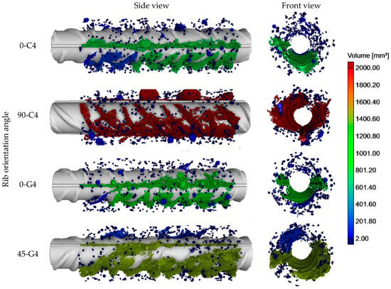
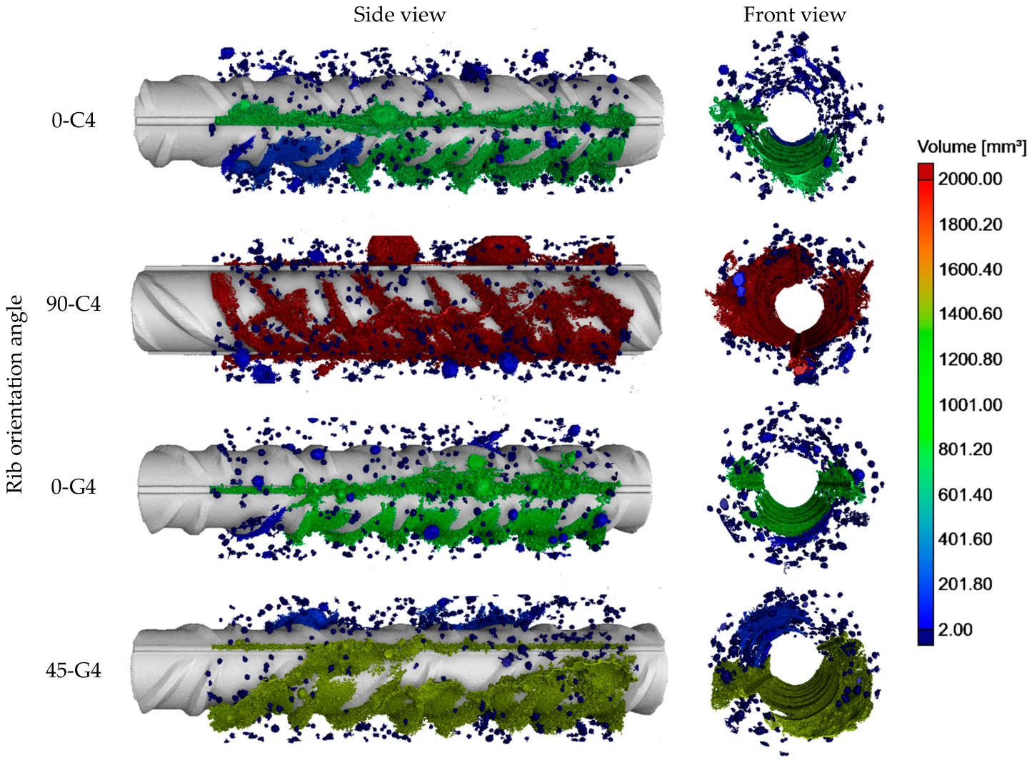
The X-ray CT scanning investigations provided visualization and quantification of air voids formed around the rebars throughout the height of the deep-beam elements, with the scans directed to the area near the rebars in order to detect entrapped air and voids caused by bleeding and settlement of the concrete. Figure 2 presents a three-dimensional view of the air voids both transverse-to-axis and with a longitudinal perspective for the rebars in poor bond conditions. The porosity analysis focused exclusively on defects with a volume greater than 0.2 mm3, which were significant for the analysis. A constant scale of void volumes was employed in the figures. Voids measuring below 2 mm3 were marked in navy, whilst those above 200 mm3 were marked in burgundy.
Figure 2.
Cover in poor bond conditions—3d reconstruction of defects.
Irrespective of the transverse rib orientation angle and the position of the bar within the element, a continuous void was observed beneath the reinforcing bars in the zone of poor bond conditions. This void resulted from the combined effects of plastic settlement of the concrete mix and bleeding. Depending on its depth and extent, this void may reduce the effective steel–concrete contact area and lead to the partial or complete exclusion of the lower part of the bar from bond stress transfer.
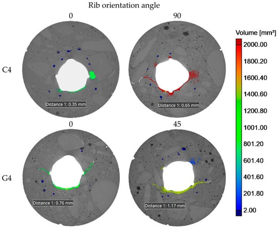
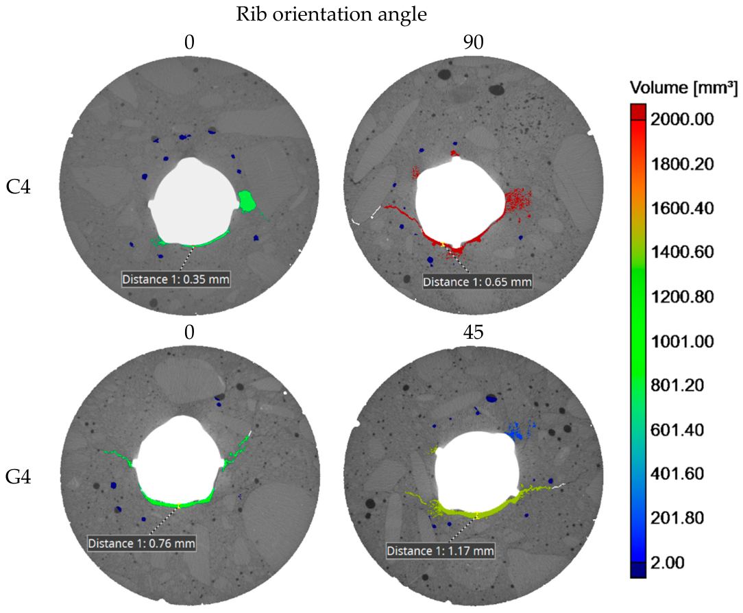
For rib orientations in which the void may extend both directly beneath the ribs and into the inter-rib spaces, i.e., for the 0° and 45° variants, the depth of the void between the ribs is of particular significance. This parameter may affect the effectiveness of mechanical interlocking between the bar and the concrete and, consequently, the quality of the bond. To assess the depth of the void beneath the reinforcing bars more accurately, Figure 3 presents cross-sections taken through the inter-rib spaces, with the void depth indicated.
Figure 3.
Cover in poor bond conditions—cross section.
The greatest void depth in the inter-rib space was observed for the bar whose transverse ribs were oriented at an angle of 45° relative to the bottom surface of the element. Considering the variable height of the transverse ribs around the circumference of the B500SP bar, it can be concluded that, in this variant, a significant portion of the lower bar surface may become ineffective in bond stress transfer.
Irrespective of the transverse rib orientation angle, greater void depths beneath the bar were observed in both specimens from column G. It should be noted, however, that the specimens from column C contained a larger number of individual large air voids. Their presence in the immediate vicinity of the ribs may have weakened the mechanical interlock between the bar and the concrete and, consequently, contributed to a greater reduction in bond stress during the initial stage of bond deterioration.
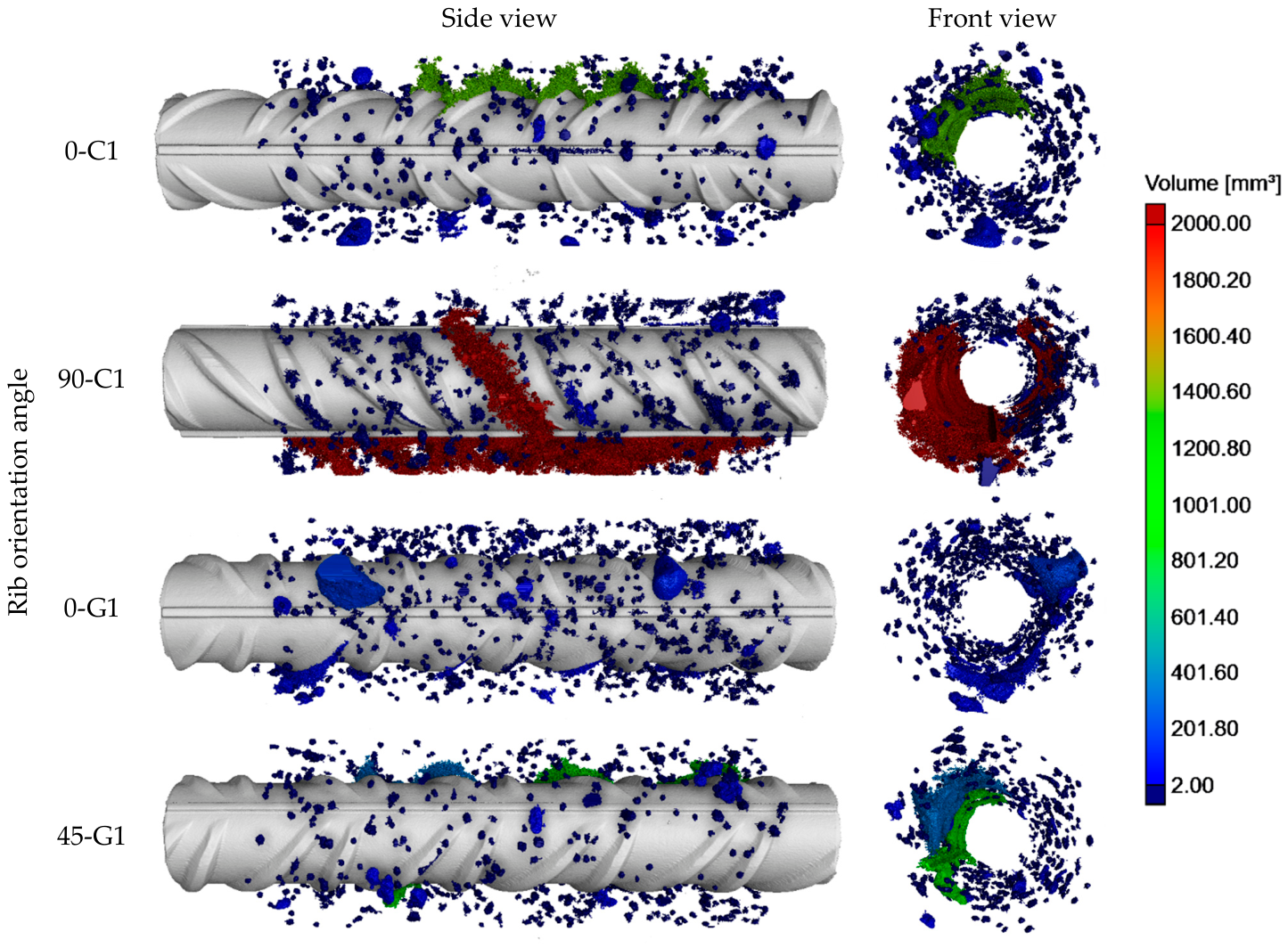
Figure 4 presents a three-dimensional view of the air voids both transverse-to-axis and with a longitudinal perspective for the rebars in good bond conditions.
Figure 4.
Cover in good bond conditions—3d reconstruction of defects.
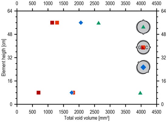
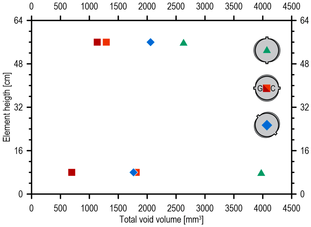
In the case of bars located in the zone of good bond conditions, no voids resulting from plastic settlement of the mix or bleeding were observed. The identified defects should therefore be primarily attributed to air entrapped during the concreting process, which was not effectively removed by the self-deaeration of the mix. For this reason, significant air voids were observed in the lower specimens from column C. Their occurrence may be associated with the continuous flow of concrete in the vicinity of column C during casting, which could have limited the effective self-deaeration of this region of the deep-beam element. This relationship is also reflected in the quantitative analysis of defects in the concrete cover around the reinforcing bars, presented in Figure 5.
Figure 5.
Total void volume in the concrete cover as a function of element height for different rebar rib orientations.
The distribution of the total void volume within the concrete cover appears to depend more strongly on the concrete placement process and the effectiveness of mix self-deaeration than on the transverse rib orientation angle. In the case of column C, a greater void volume was identified in the cover of the lower bars, which is most likely attributable to air entrapped during concreting. In the upper part of the deep-beam elements, irrespective of the analysed column, voids associated with plastic settlement of the mix and bleeding were observed. Owing to the additional presence of several large spherical air voids in the cover of the bar with transverse ribs oriented at 90°, the total void volume was highest in this case.
4. Conclusions
This study assessed whether the orientation of transverse ribs on reinforcing bars can influence void formation at the SCI, particularly under conditions favouring plastic settlement of the concrete mix and bleeding.
The findings of the present study indicate that the formation of voids within the concrete cover surrounding reinforcing bars is influenced primarily by factors related to concrete casting and the ability of the fresh mix to release entrapped air, whereas the effect of the transverse rib orientation angle appears to be of secondary importance. Irrespective of the rib orientation angle, continuous voids were observed beneath the reinforcing bars in the zone of poor bond conditions. Depending on their depth and extent, these voids may lead to the partial or complete exclusion of the lower part of the bar from effective bond stress transfer.
Author Contributions
Conceptualization, M.K. and P.D.; methodology, M.K. and P.D.; validation, M.K. and P.D.; formal analysis, M.K.; investigation, M.K.; resources, M.K.; data curation, M.K.; writing—original draft preparation, M.K.; writing—review and editing, M.K. and P.D.; visualization, M.K.; supervision, M.K.; project administration, M.K.; funding acquisition, M.K. and P.D. All authors have read and agreed to the published version of the manuscript.
Funding
Research project supported by the programme “Excellence initiative–research university” (IDUB) for the AGH University of Krakow, and the institutional subsidy for scientific research activities.
Institutional Review Board Statement
Not applicable.
Informed Consent Statement
Not applicable.
Data Availability Statement
The raw data supporting the conclusions of this article will be made available by the authors on request.
Acknowledgments
The authors would like to express their gratitude to the Steel Quality Promotion Centre (CPJS) for providing reinforcement steel. During the preparation of this manuscript, the authors used ChatGPT 5.5 for the purposes of language editing and improving the clarity and readability of the text. The authors have reviewed and edited the output and take full responsibility for the content of this publication.
Conflicts of Interest
The authors declare no conflicts of interest. The funders had no role in the design of the study; in the collection, analyses, or interpretation of data; in the writing of the manuscript; or in the decision to publish the results.
Abbreviations
The following abbreviations are used in this manuscript:
| SCI | Steel–concrete interface |
| X-ray CT | X-ray computed tomography |
| SCC | Self-compacting concrete |
| ROI | Region of interest |
References
- Powers, T.C. The Properties of Fresh Concrete; John Wiley & Sons Inc.: Hoboken, NJ, USA, 1968; ISBN 9784716959043. [Google Scholar]
- Reza Esfahani, M.; Lachemi, M.; Reza Kianoush, M. Top-Bar Effect of Steel Bars in Self-Consolidating Concrete (SCC). Cem. Concr. Compos. 2008, 30, 52–60. [Google Scholar] [CrossRef] [Scilit]
- Zhang, R.; Castel, A.; François, R. Influence of Steel–Concrete Interface Defects Owing to the Top-Bar Effect on the Chloride-Induced Corrosion of Reinforcement. Mag. Concr. Res. 2011, 63, 773–781. [Google Scholar] [CrossRef] [Scilit]
- EN 1992-1-1:2024-05; Design of Concrete Structures, Part 1-1: General Rules and Rules for Buildings, Bridges and Civil Engineering Structures. European Committee for Standardization: Brussels, Belgium, 2024.
- ACI 318-19; ACI Committee 318 Building Code Requirements for Structural Concrete. American Concrete Institute: Farmington Hills, MI, USA, 2019; ISBN 0870311719.
- Azizinamini, A.; Stark, M.; Roller, J.J.; Ghosh, S.K. Bond Performance of Reinforcing Bars Embedded in High-Strength Concrete. ACI Struct. J. 1993, 90, 554–561. [Google Scholar] [CrossRef] [Scilit]
- Zhang, X.; Zhao, Y.; Bernal, S.A. Applicability Discussion for Multi-Peak Gaussian Model of Corrosion Layer at Steel/Concrete Interfaces. Mater. Struct. 2021, 54, 55. [Google Scholar] [CrossRef] [Scilit]
- Soylev, T.A.; François, R. Quality of Steel–Concrete Interface and Corrosion of Reinforcing Steel. Cem. Concr. Res. 2003, 33, 1407–1415. [Google Scholar] [CrossRef] [Scilit]
- Castel, A.; Vidal, T.; Viriyametanont, K.; François, R. Effect of Reinforcing Bar Orientation and Location on Bond with Self-Consolidating Concrete. ACI Struct. J. 2006, 103, 559–567. [Google Scholar] [CrossRef] [Scilit] [PubMed]
- Monteiro, P.J.M.; Gjorv, O.E.; Mehta, P.K. Effect of Condensed Silica Fume on the Steel-Cement Paste Transition Zone. Cem. Concr. Res. 1989, 19, 114–123. [Google Scholar] [CrossRef] [Scilit]
- Chen, F.; Li, C.Q.; Baji, H.; Ma, B. Quantification of Steel-Concrete Interface in Reinforced Concrete Using Backscattered Electron Imaging Technique. Constr. Build. Mater. 2018, 179, 420–429. [Google Scholar] [CrossRef] [Scilit]
- Horne, A.T.; Richardson, I.G.; Brydson, R.M.D. Quantitative Analysis of the Microstructure of Interfaces in Steel Reinforced Concrete. Cem. Concr. Res. 2007, 37, 1613–1623. [Google Scholar] [CrossRef] [Scilit]
- Goudar, S.K.; Das, B.B.; Arya, S.B.; Shivaprasad, K.N. Influence of Sample Preparation Techniques on Microstructure and Nano-Mechanical Properties of Steel-Concrete Interface. Constr. Build. Mater. 2020, 256, 119242. [Google Scholar] [CrossRef] [Scilit]
- Kenny, A.; Katz, A. Statistical Relationship between Mix Properties and the Interfacial Transition Zone around Embedded Rebar. Cem. Concr. Compos. 2015, 60, 82–91. [Google Scholar] [CrossRef] [Scilit]
- Moccia, F.; Kubski, X.; Fernández Ruiz, M.; Muttoni, A. The Influence of Casting Position and Disturbance Induced by Reinforcement on the Structural Concrete Strength. Struct. Concr. 2021, 22, E655–E682. [Google Scholar] [CrossRef] [Scilit]
- Dybeł, P. Effect of Bottom-up Placing of Self-Compacting Concrete on Microstructure of Rebar-Concrete Interface. Constr. Build. Mater. 2021, 299, 124359. [Google Scholar] [CrossRef] [Scilit]
- Rossi, E.; Polder, R.; Copuroglu, O.; Nijland, T.; Šavija, B. The Influence of Defects at the Steel/Concrete Interface for Chloride-Induced Pitting Corrosion of Naturally-Deteriorated 20-Years-Old Specimens Studied through X-Ray Computed Tomography. Constr. Build. Mater. 2020, 235, 117474. [Google Scholar] [CrossRef] [Scilit]
- Fang, G.; Ding, W.; Liu, Y.; Zhang, J.; Xing, F.; Dong, B. Identification of Corrosion Products and 3D Distribution in Reinforced Concrete Using X-Ray Micro Computed Tomography. Constr. Build. Mater. 2019, 207, 304–315. [Google Scholar] [CrossRef] [Scilit]
- Dybeł, P.; Kucharska, M. X-Ray CT Investigation of Bond Mechanism in Reinforced SCC Elements of Different Placement Technology. Materials 2021, 14, 6236. [Google Scholar] [CrossRef] [Scilit]
- Zhang, P.; Liu, Z.; Wang, Y.; Yang, J.; Han, S.; Zhao, T. 3D Neutron Tomography of Steel Reinforcement Corrosion in Cement-Based Composites. Constr. Build. Mater. 2018, 162, 561–565. [Google Scholar] [CrossRef] [Scilit]
- Robuschi, S.; Tengattini, A.; Dijkstra, J.; Fernandez, I.; Lundgren, K. A Closer Look at Corrosion of Steel Reinforcement Bars in Concrete Using 3D Neutron and X-Ray Computed Tomography. Cem. Concr. Res. 2021, 144, 106439. [Google Scholar] [CrossRef] [Scilit]
- EN 12350-8; Testing Fresh Concrete, Part 8: Self-Compacting Concrete—Slump-Flow Test. European Committee for Standardization: Brussels, Belgium, 2010.
- EN 12350-10; Testing Fresh Concrete, Part 10: Self-Compacting Concrete—L-Box Test. European Committee for Standardization: Brussels, Belgium, 2010.
- Elhassan, A. The Effects of Visual Stability Index (VSI) on Fresh Segregation of Self Consolidating Concrete (SCC) Using Fly Ash Class C and F. Master’s Thesis, University of Tennessee at Chattanooga, Chattanooga, TN, USA, 2014. [Google Scholar]
- ASTM C1611; Standard Test Method for Slump Flow of Self-Consolidating Concrete. ASTM International: West Conshohocken, PA, USA, 2018.

Disclaimer/Publisher’s Note: The statements, opinions and data contained in all publications are solely those of the individual author(s) and contributor(s) and not of MDPI and/or the editor(s). MDPI and/or the editor(s) disclaim responsibility for any injury to people or property resulting from any ideas, methods, instructions or products referred to in the content. |
© 2026 by the authors. Licensee MDPI, Basel, Switzerland. This article is an open access article distributed under the terms and conditions of the Creative Commons Attribution (CC BY) license.