


Abstract
This paper presents the use of prestressing as a design tool for solving complex structural requirements in the reconstruction of Hotel Marjan in Split. The architectural concept includes long spans, restricted structural depths, swimming pools, significant cantilevers, and discontinuities in the vertical load-bearing system. Four characteristic post-tensioned systems are analysed: shallow transfer beams above the main entrance, wide beams spanning approximately 18.5 m above the congress hall, beams supporting the swimming-pool structures, and a bidirectionally post-tensioned cantilever transfer grillage below the tower. Particular attention is paid to staged stressing, realistic numerical modelling, and the influence of tendon ducts on the effective concrete cross-section. The examples demonstrate that prestressing enables active control of load paths and deformations and allows architectural solutions that would be difficult to achieve rationally with conventional reinforced concrete.
1. Introduction
Prestressing is an effective means of achieving long spans with limited structural depth and can significantly improve structural efficiency and architectural flexibility in buildings [1,2,3]. Contemporary architecture increasingly requires column-free spaces, large cantilevers, and discontinuities in vertical load-bearing systems [4]. Under such conditions, prestressing should be regarded not only as a means of increasing resistance or reducing deflections, but as a design tool for controlling stresses, deformations, and load paths, including during staged construction.
Shallow wide post-tensioned beams are particularly efficient in long-span floor systems, but their geometry requires appropriate numerical representation. Modelling plate or shell elements in their actual mid-surfaces and connecting eccentric nodes by kinematic links provides a more realistic representation of stiffness, stress distribution, and shear-lag effects [5,6]. Post-tensioned floor systems can also provide material savings and increased functional flexibility [7].
The reconstruction and extension of Hotel Marjan in Split provides a case in which these requirements occur simultaneously. The architectural concept combines a hotel tower, an open entrance area, a long-span congress hall, swimming pools and pool-plant areas, and a highly complex transfer of loads between the upper and lower parts of the building. Prestressing was therefore applied to several structurally distinct elements.
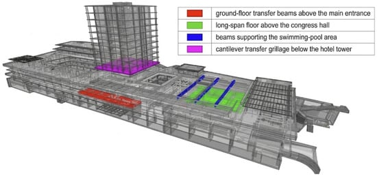
Four characteristic solutions are analysed in this paper: ground-floor transfer beams above the main entrance, shallow wide beams above the congress hall, post-tensioned beams supporting the swimming-pool structures, and, as the most complex element, a bidirectionally post-tensioned cantilever transfer grillage that collects and redistributes the vertical loads from ten storeys of the hotel tower. The locations of the analysed systems are shown in Figure 1.
Figure 1.
Reconstruction of Hotel Marjan—3D model and locations of the analysed prestressed structural systems.
The aim of the paper is not to present the complete structural analysis of the building, but to demonstrate, through a real-world project, different ways in which prestressing can be used as an integral part of the structural concept—from increasing spans and reducing structural depth to controlling large transfer forces and construction stages.
2. Project and Design Approach
Hotel Marjan combines a hotel tower, long-span public spaces, a congress hall, swimming pools, and pool-plant areas. The different functions of individual floors create significant discontinuities in the vertical load-bearing system, while the architectural design restricts the available depth of several transfer elements.
Local post-tensioned solutions were therefore developed for the individual structural problems. Unbonded single-strand BBR VT CONA CMM 0106 tendons (BBR VT International Ltd., Schwerzenbach, Switzerland) were used for shallow wide floor and transfer beams, while large concentrated forces were resisted by bonded multi-strand CONA CMI BT 1506 and 1906 tendons and smaller CONA CMF 0406 tendons [8]. In the tower transfer grillage, the initial force of a single CONA CMI BT 1906 tendon is approximately 3990 kN.
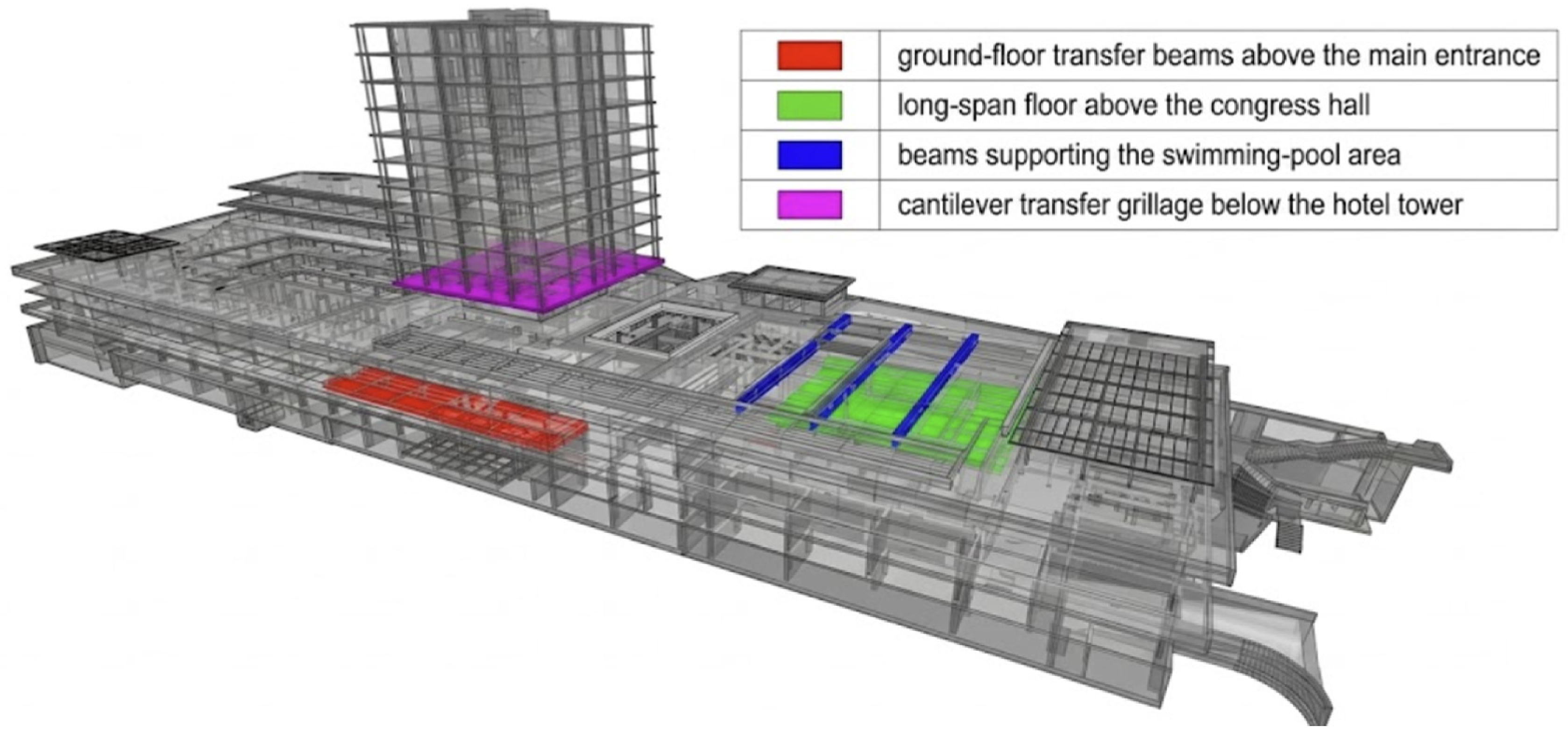
The numerical analysis was adapted to the structural behaviour of each element. Shallow wide beams were modelled using plate elements in their actual mid-surfaces connected by kinematic links [5]. For the transfer grillage, three numerical idealisations of different levels of complexity were additionally compared: a beam model, a conservative shell model with reduced slab thicknesses, and a shell model with full slab thicknesses. The adopted modelling approach is illustrated in Figure 2. The analyses were performed primarily in Tower 8.5 (Radimpex Software d.o.o., Belgrade, Serbia), while an independent verification model was developed in SOFiSTiK 2026 (SOFiSTiK AG, Germany).
Figure 2.
Numerical modelling of shallow wide beams with eccentric mid-surfaces and kinematic links.
Prestressing was considered together with the construction stages. In transfer elements, the final prestressing action was not necessarily introduced at once; instead, groups of tendons were activated progressively as the gravity loading of the structure increased.
3. Prestressed Transfer Beams Above the Main Entrance
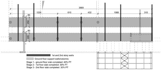
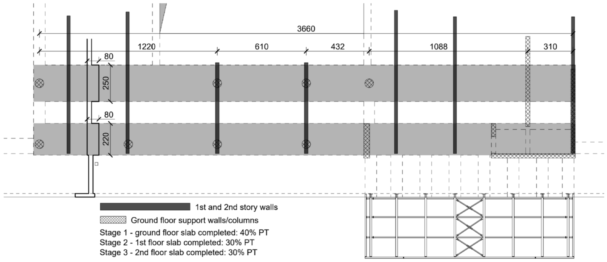
In the southern part of the ground-floor slab, the architectural requirement was to create an open main entrance without columns that would obstruct the functional and visual continuity of the space. At the same location, the load-bearing system of the upper floors does not coincide with the supports at ground-floor level. Two wide post-tensioned beams in the ground-floor slab support the walls of the first and second floors as well as part of the entrance-canopy structure. Shallow wide beams with cross-sections of approximately 250 × 80 cm and 220 × 80 (100) cm were adopted and post-tensioned with unbonded single-strand tendons. The beam arrangement and staged stressing sequence are shown in Figure 3.
Figure 3.
Prestressed transfer beams above the main entrance and staged stressing sequence.
Prestressing allowed the required resistance and stiffness to be achieved primarily by increasing the beam width, without introducing deep transfer beams into the entrance space.
A distinctive feature of the solution is the staged activation of prestressing during construction. Approximately one week after concreting the ground-floor slab, 40% of the total number of tendons were stressed. After completion of the first-floor slab, when its concrete had reached approximately 70% of the specified compressive strength, an additional 30% of the tendons were stressed. The remaining 30% were stressed after concreting the second-floor slab. Thus, 40%, 70%, and finally 100% of the tendons were stressed as the permanent load from the upper floors increased.
This procedure prevented excessive initial camber and unfavourable stress states while the final gravity load was not yet present. Prestressing was therefore used not only for the final structural state but also as a means of controlling deformations and stresses during construction.
Because of the large beam width, the slab and thickened zones were modelled in their actual mid-surfaces and connected by kinematic links, allowing the actual neutral axis position and stress distribution across the section width to be represented.
4. Long-Span Prestressed Beams Above the Congress Hall
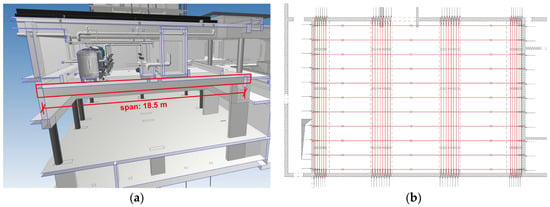
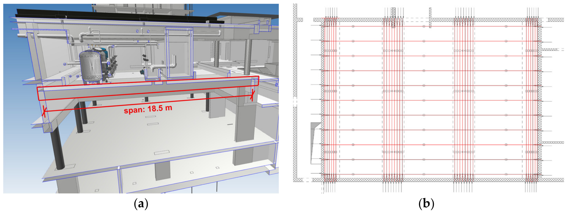
The floor structure above the congress hall was designed for a clear span of 18.5 m under a strict limitation on structural depth. Large permanent loads from pool-plant rooms, tanks, and swimming-pool facilities located above the hall represented an additional unfavourable condition. A system of shallow wide post-tensioned beams, approximately 2.5 m wide and integrated into the floor structure, was therefore adopted. The reinforced concrete slab is 28 cm thick, and the beams are arranged at a spacing of approximately 8.1 m.
The beams are post-tensioned with unbonded BBR VT CONA CMM 0106 single-strand tendons. The tendon layout and profile follow the distribution of gravity moments, with increased eccentricity in the spans and tendons rising towards the upper part of the section over the supports. Prestressing made it possible to achieve a span of almost 19 m with a structural depth of only about 1.0 m, corresponding to L/h ≈ 18–19, under loads several times higher than those of conventional floor structures. The structural arrangement and tendon layout are shown in Figure 4.
Figure 4.
Long-span prestressed floor structure above the congress hall: (a) section through the congress hall, with the pool-plant room on the left and the indoor swimming-pool area on the right; (b) BBR VT CONA CMM 0106 tendon layout.
Because of their large width, the beams cannot be represented adequately by a conventional one-dimensional beam model. The slab and thickened zones were modelled with plate elements in their actual mid-surfaces and connected by kinematic links. This provides a more realistic representation of system stiffness, migration of the neutral axis, and shear-lag effects [5]. An additional model with vertically offset beams was used to verify the behaviour of the actual T-section.
For such a slender system, serviceability was one of the principal design criteria. Structural states immediately after stressing and the final long-term states were checked, including creep, shrinkage, and prestress losses.
This example demonstrates how prestressing can reconcile a long clear span with a small available structural depth, while appropriate numerical idealisation becomes an integral part of the rational design of shallow wide beams.
5. Prestressed Beams Supporting Swimming Pools
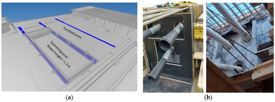
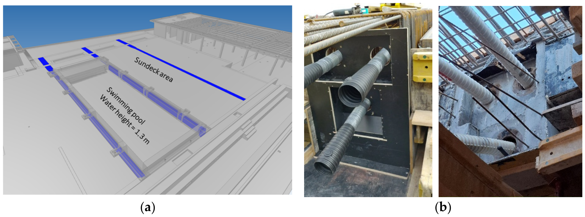
At the second-floor slab level, three main post-tensioned beams support the swimming-pool structures and the associated high gravity loads. The beams have an overall depth of approximately 1.30 m, a main span of approximately 18.5 m, and continue into cantilever segments. Their geometry follows directly from the pool level changes and the arrangement of pool-plant spaces; they therefore act simultaneously as the main load-bearing elements and as part of the spatial organisation of the pool structure. The nominal beam width specified in the technical documentation is 60 cm.
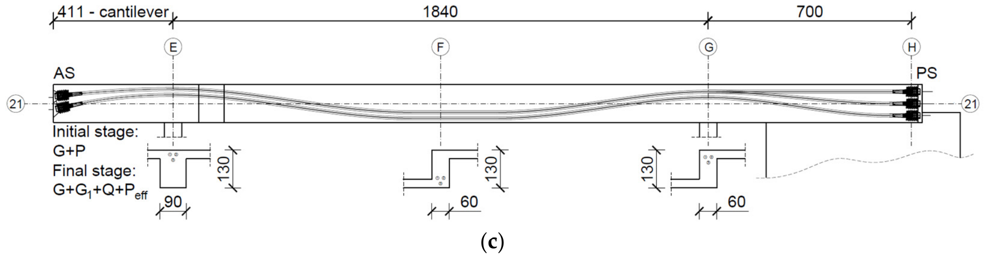
Unlike the preceding shallow floor systems, the high forces in these beams required three bonded multi-strand BBR VT CONA CMI BT 1506 tendons per beam. The initial force of one tendon is approximately 3150 kN, giving a total nominal initial prestressing force of P0 = 3 × 3150 = 9450 kN per beam.
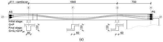
The tendons are grouted after stressing, and their spatial profiles, active and passive anchorages, and stressing sequence were defined in detail. The lower tendon is stressed first from the cantilever side, while the remaining two tendons are stressed from the opposite side.
The principal design challenge arose from the pronounced difference between the initial and final structural states, as well as from determination of the effective section properties because the cross-sectional geometry changes along the beam. At the time of stressing, the beams carry mainly the self-weight of the completed structural concrete, whereas very large additional permanent loads from the pools, water, and technical equipment are introduced later. For one characteristic beam, the additional permanent load is approximately 4830 kN compared with a self-weight of about 3880 kN, in addition to the imposed load. Staged stressing was not feasible because of the construction technology and geometry, and all tendons had to be stressed immediately after completion of the beams and slab. The beam layout, anchorage details, and tendon profile are shown in Figure 5.
Figure 5.
Prestressed beams supporting the swimming-pool structure: (a) 3D view of the prestressed beams and swimming-pool area; (b) post-tensioning ducts at the anchorage zone before and after concreting; (c) longitudinal profile of a characteristic beam with 3 × CONA CMI BT 1506 tendons.
The prestressing force and tendon profile therefore could not be determined only from the final gravity moment. Excessive prestressing would be unfavourable in the initial stage, when the additional loads are not yet present, whereas insufficient prestressing would lead to excessive deformations and stresses in the final state. The design was therefore based on balancing the initial G + P state against the final G + G1 + Q + Peff state. Because the additional permanent and imposed loads are large relative to self-weight, achieving an optimum prestressing level and acceptable behaviour in both states is particularly demanding.
The complex tendon profile was additionally governed by cantilever action and by large bending moments of both signs along the same beam. Numerical analyses give bending moments of approximately +4.5 to −5.6 MNm and shear forces exceeding 2 MN. These actions, together with the limited space available for anchorages and tendon routing, justified the use of a high-capacity concentrated bonded system.
This example shows that, in complex post-tensioned members, the objective is not to maximise the balancing of gravity effects, but to select a prestressing force and tendon geometry that provide acceptable structural behaviour throughout the complete loading sequence.
6. Bidirectionally Prestressed Cantilever Transfer Grillage
6.1. Structural Concept and Prestressing Layout
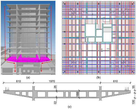
The structurally most demanding application of prestressing was implemented at the third-floor slab level, directly below the hotel tower. At this level the structural system changes significantly. The slabs from the fourth to the thirteenth floor are supported by the reinforced concrete core, cantilever wall beams (wings), and perimeter columns. At the third-floor level, the loads from these elements must be collected and redistributed to the load-bearing elements of the lower part of the building. The transfer structure therefore directly carries the vertical loads from ten storeys of the hotel tower.
An additional challenge results from the tower geometry. Some perimeter columns are located outside the immediate zone of the vertical supports of the lower structure, so the transfer floor acts as a pronounced cantilever. A conventional flat slab or a system of deep transfer beams could not simultaneously satisfy the requirements for resistance, deformation control, and available structural depth. A bidirectionally post-tensioned reinforced concrete box grillage was therefore developed, whose spatial action and geometry enable the transfer of large concentrated column forces.
The overall depth of the grillage varies from approximately 55 to 155 cm. It consists of a 26 cm thick top slab, a 22 cm thick bottom slab, and ribs 30–100 cm wide. The bottom slab is partly inclined, so that together with the top slab and ribs it forms a spatial box system. Concrete C40/50 and prestressing steel Y1860 were used.
Prestressing is arranged in two orthogonal directions using bonded tendons of different capacities. The main CONA CMI BT 1906 tendons have an initial force of approximately 3990 kN and ducts with an outer diameter of 110 mm; CONA CMI BT 1506 tendons have an initial force of approximately 3150 kN, while smaller CONA CMF 0406 tendons with an initial force of approximately 840 kN are used in local zones.
This arrangement allows the concentrated column loads to be redistributed through the spatial system towards the reinforced concrete core and the other supports rather than being transferred in only one dominant direction. The structural concept, tendon layout, and characteristic cross-section are shown in Figure 6.
Figure 6.
Structural concept and bidirectional prestressing of the cantilever transfer grillage: (a) 3D section through the tower, transfer grillage, and load path; (b) simplified tendon layout in the X and Y directions; (c) characteristic cross-section of the transfer grillage.
6.2. Effect of Tendon Ducts on the Effective Concrete Cross-Section
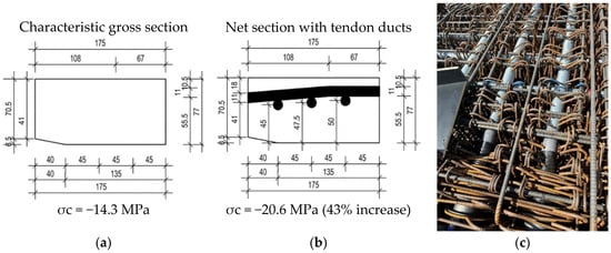
The large number of high-capacity tendons in two directions created a local problem that is not usually governing in conventional post-tensioned members. At critical sections, tendons running along a rib are crossed by ducts of tendons in the perpendicular direction. During stressing, the portion of the concrete cross-section occupied by the ungrouted ducts does not participate in carrying the large compressive prestressing force.
For this reason, the gross and net concrete sections were analysed separately at characteristic critical locations. Tendon ducts and other openings were explicitly removed from the section geometry, after which the area, centroid position, moments of inertia, and section moduli were recalculated.
The effect of this reduction proved significant. At one critical section, the concrete area decreases from approximately 13,345 cm2 to 11,135 cm2, while the maximum compressive stress increases from approximately 14.3 to 20.6 MPa, i.e., by about 43%. At another characteristic section, the compressive stress increases from approximately 15.0 to 21.5 MPa, while a tensile stress of approximately 3.3 MPa develops at the opposite edge. For C40/50, the adopted limits of 24 MPa in compression and 3.5 MPa in tension correspond to 0.60fck and fctm, respectively, for the characteristic (rare) SLS combination, following EN 1992-1-1 as adopted in the project [1,8]. The analyses of other sections gave increases in maximum stress of approximately 12–48%, depending on the rib geometry and the number of ducts crossing the section.
This example demonstrates that, in heavily post-tensioned bidirectional systems, local reduction of the concrete section by tendon ducts can significantly influence the stress state precisely during stressing and should not be neglected in the verification of concrete stresses. The gross and net sections and a construction detail are shown in Figure 7.
Figure 7.
Effect of intersecting tendon ducts on the effective concrete cross-section: (a) characteristic gross section; (b) corresponding net section including tendon ducts; (c) construction detail showing large tendon ducts within the heavily reinforced transfer grillage.
6.3. Staged Prestressing and Numerical Verification
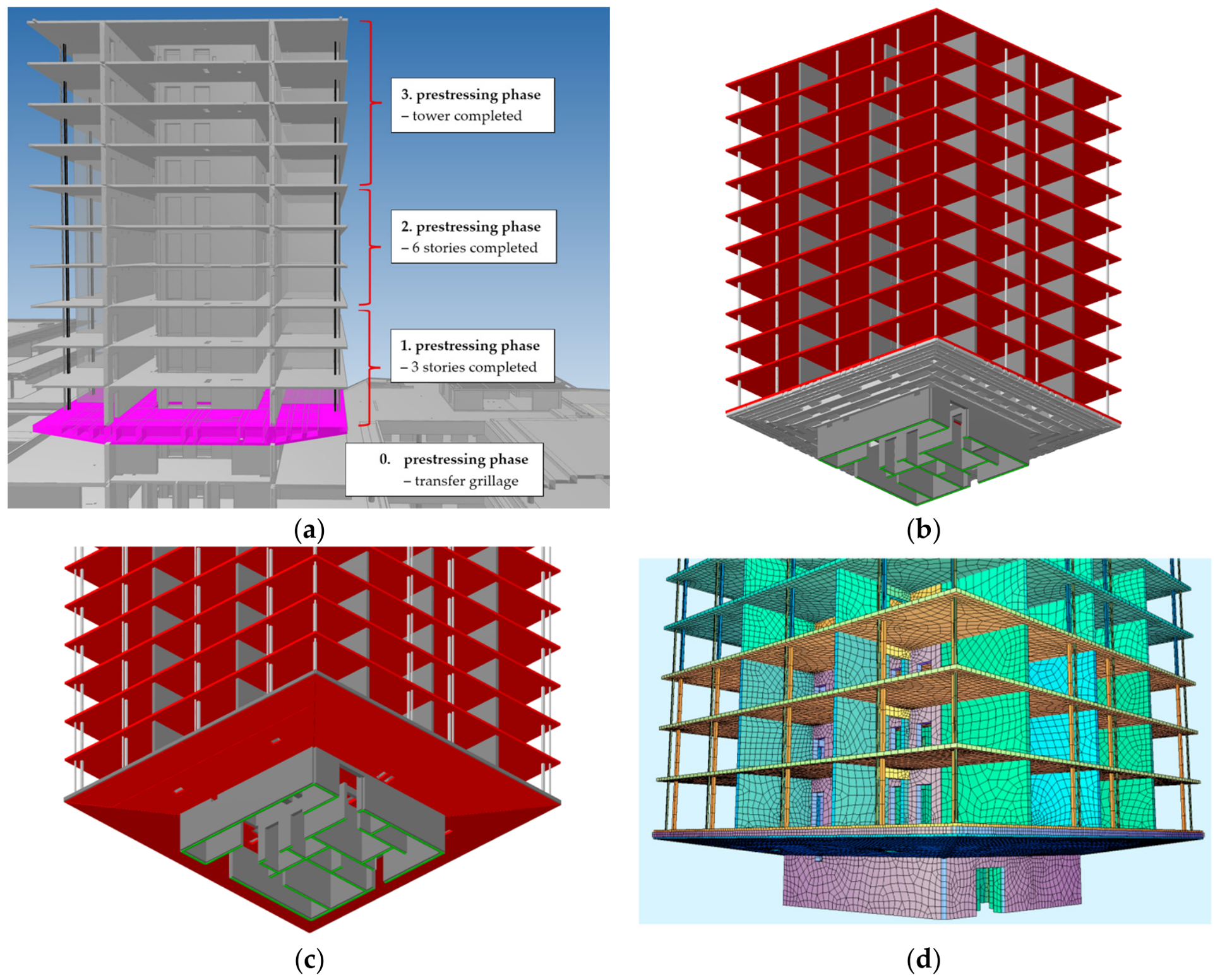
The full prestressing force could not be introduced immediately after concreting the grillage because the gravity load of the complete hotel tower was not yet present. Conversely, postponing all stressing until completion of the tower would have resulted in progressively increasing grillage deformations and stresses during construction. Prestressing was therefore coordinated with the construction sequence and divided into four stages, F0–F3.
In stage F0, the initial tendon group is stressed approximately three to four weeks after concreting the grillage, when the concrete has reached a compressive strength of approximately 38 MPa. These tendons are stressed and grouted at least two weeks before the next stage because they pass close to the anchorage zones of subsequently activated tendons.
Stage F1 is carried out after completion of the fourth- and fifth-floor structures, with the sixth-floor structure already cast, corresponding to three constructed storeys above the transfer grillage. In stage F2, the structure has reached the ninth floor, corresponding to six constructed storeys above the grillage. The final stage F3 is carried out during construction of the twelfth and thirteenth floors. Tendons belonging to each stage are grouted immediately after stressing.
In this way, the active prestressing level increases in parallel with the gravity load of the tower. As in the ground-floor transfer beams, the timing of tendon activation becomes an integral part of the structural concept, but here the process extends through practically the entire construction of the upper part of the building.
Because of the spatial behaviour of the grillage, three numerical idealisations were compared. Model 1 represented the ribs by beam elements and neglected the stiffness contribution of the slabs. Model 2 used shell elements for the ribs and slabs, with reduced slab thicknesses to conservatively account for tendon-duct weakening during stressing. Model 3 used shell elements with full slab thicknesses and was considered more representative of the global final-state stiffness. For the same governing load combination, the total vertical displacement at the perimeter column locations was approximately 28.9 mm in Model 1 and 17.6 mm in Model 2; Model 3 gave a further reduction of about 8%, to approximately 16.2 mm. Thus, shell modelling reduced the predicted cantilever deflection by about 39% relative to the beam model, confirming the importance of spatial box action. The conservative long-term design check in Model 1 gave a maximum deflection of approximately 30 mm, below the adopted limit of 36 mm, corresponding to L/150 for the approximately 5.4 m cantilever; a construction camber of 15 mm was specified at the grillage corners [8].
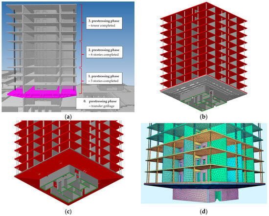
The comparison demonstrates that the assumed global stiffness directly affects both cantilever deformation and the redistribution of reactions between the perimeter columns, the core, and the other supports. Because the three models use different element formulations, local concrete stresses were verified separately on gross and net sections as described in Section 6.2. The construction stages and numerical models are summarised in Figure 8.
Figure 8.
Construction stages and numerical verification of the transfer grillage: (a) 3D view of the tower showing prestressing stages F0, F1, F2, and F3; (b) Model 1, with the grillage represented by beam elements; (c) Models 2 and 3, with the grillage represented by shell elements using reduced slab thicknesses in Model 2 and full slab thicknesses in Model 3; (d) independent SOFiSTiK control model using shell elements for additional verification.
7. Discussion
The four applications demonstrate that prestressing addressed different structural constraints within the same building: limited structural depth and vertical discontinuity at the main entrance, a long clear span above the congress hall, strongly differing initial and final loading states in the swimming-pool beams, and large concentrated loads combined with bidirectional spatial action in the tower transfer grillage. In all cases, the choice of prestressing was governed not only by ultimate resistance but also by serviceability, architectural constraints, and construction sequence.
The examples also emphasise the importance of physically appropriate numerical modelling and detailing. Eccentric mid-surfaces and shear-lag effects are relevant for shallow wide beams, while shell modelling is required to capture the spatial action of the box transfer grillage. In heavily post-tensioned members, tendon ducts may significantly reduce the effective concrete section; in the analysed grillage this increased calculated local stresses by up to approximately 48%. The design of such systems therefore requires simultaneous consideration of global load paths, structural geometry and stiffness, construction stages, and local tendon detailing.
8. Conclusions
The following conclusions can be drawn from the presented examples:
- Prestressing enables long spans, significant cantilevers, and transfer of large loads to be achieved with structural depths that would be difficult to realise rationally using conventional reinforced concrete solutions.
- The design of transfer structures should not be limited to the final structural state. Staged activation of prestressing makes it possible to coordinate the prestressing action with the progressive increase in gravity loading during construction.
- For shallow wide post-tensioned members, realistic numerical representation of the geometry, including eccentric mid-surfaces and shear-lag effects, is essential for reliable assessment of stiffness, stresses, and deformations.
- For the transfer grillage, shell modelling reduced the predicted cantilever deflection by about 39% relative to the beam model, while local section reduction by tendon ducts increased concrete stresses by up to 48%; both effects therefore require explicit verification.
- The Hotel Marjan project demonstrates that prestressing in building structures should primarily be regarded as a design tool for controlling load paths, deformations, and construction stages, enabling architecturally demanding structural concepts to be realised with rational member dimensions.
Author Contributions
Conceptualization, J.G.; methodology, J.G.; software, J.G., P.P., and I.G.; validation, J.G., P.P. and I.G.; formal analysis, J.G.; investigation, J.G.; writing—original draft preparation, J.G.; writing—review and editing, J.G. and F.C.; visualisation, F.C. All authors have read and agreed to the published version of the manuscript.
Funding
This research received no external funding.
Institutional Review Board Statement
Not applicable.
Informed Consent Statement
Not applicable.
Data Availability Statement
The data presented in this paper are contained within the article and the cited project documentation. Additional project data are not publicly available due to contractual restrictions.
Conflicts of Interest
Author P.P. was employed by BBR Adria Ltd. Author F.C. was employed by Radionica Statike Ltd. The remaining authors declare that the research was conducted in the absence of any commercial or financial relationships that could be construed as a potential conflict of interest.
References
- EN 1992-1-1:2004; Eurocode 2: Design of Concrete Structures—Part 1-1: General Rules and Rules for Buildings. CEN: Brussels, Belgium.
- Morgen, K.; Diedrich, N.; Wollrab, E. Flachdecken mit Vorspannung ohne Verbund nach DIN 1045-1. Beton Stahlbetonbau 2004, 99, 914–928. [Google Scholar] [CrossRef] [Scilit]
- Fédération Internationale du Béton (FIB). Post-Tensioning in Buildings; FIB Bulletin No. 31; FIB: Lausanne, Switzerland, 2005. [Google Scholar]
- Presečki, P.; Bodiroga, Ž. Naknadno prednapete konzolne ploče velikih raspona. In Proceedings of the Suvremena Građevinska Praksa, Ruma, Serbia, 8–9 June 2023. [Google Scholar]
- Presečki, P.; Kovač, M.; Pičulin, S. Kinematičke veze u proračunima prednapetih AB ploča. Građevinar 2007, 59, 83–97. [Google Scholar]
- Presečki, P.; Kovač, M.; Soldo, B. Modelling post-tensioned slabs using kinematic connections. In Proceedings of the International Scientific Conference People, Buildings and Environment, Lednice, Czech Republic, 7–9 November 2012. [Google Scholar]
- Galić, J.; Presečki, P.; Miljanović, V. Post-Tensioned Slabs in Garages—A Rational Choice. Key Eng. Mater. 2025, 1011, 51–60. [Google Scholar] [CrossRef] [Scilit]
- Galić, J.; Galić, B.; Cvetko, F.; Marković, B. Reconstruction of Hotel Marjan, Split—Structural Design, Volumes 1–7; unpublished project documentation; Radionica Statike d.o.o.: Zagreb, Croatia, 2025. [Google Scholar]
Disclaimer/Publisher’s Note: The statements, opinions and data contained in all publications are solely those of the individual author(s) and contributor(s) and not of MDPI and/or the editor(s). MDPI and/or the editor(s) disclaim responsibility for any injury to people or property resulting from any ideas, methods, instructions or products referred to in the content. |
© 2026 by the authors. Licensee MDPI, Basel, Switzerland. This article is an open access article distributed under the terms and conditions of the Creative Commons Attribution (CC BY) license.