


Abstract
This paper numerically investigates the effect of baffle number on the thermal and hydraulic performance of a shell-and-tube heat exchanger using molten salts as heat transfer fluids. Lithium fluoride (LiF) and FLiBe (LiF–BeF2) were used as the working fluids due to their favorable thermophysical properties and suitability for high-temperature energy systems. Four different shell-and-tube heat exchanger geometries are considered: a configuration without baffles and configurations containing two-, three-, and four-row baffles. Computational fluid dynamics (CFD) simulations were carried out using ANSYS Fluent to evaluate the influence of the baffle arrangement on the flow and heat transfer characteristics of the heat exchanger. In this study, heat transfer rate, temperature distribution, velocity distribution, turbulence characteristics, and pressure drop were investigated. The numerical results showed that increasing the number of baffles enhanced flow disturbance and turbulence intensity, resulting in an increase in the heat transfer rate. However, the improvement in thermal performance was accompanied by an increase in pressure drop.
1. Introduction
Heat transfer between two or more fluids at different temperatures is one of the most common processes encountered in engineering applications. This heat transfer can be carried out through direct or indirect contact between the fluids, and the devices used to perform this process are called heat exchangers.
Molten salts are considered promising heat transfer fluids for nuclear and solar energy applications thanks to their outstanding properties, such as high volumetric heat capacity, elevated boiling point, low vapor pressure, and excellent thermal stability [1]. These characteristics enable molten salts to operate safely and efficiently at high temperatures, making them suitable for advanced thermal energy storage and heat transfer systems. In particular, their ability to store and transport large amounts of thermal energy contributes to improving the overall efficiency and reliability of energy conversion processes. Therefore, molten salts are used widely in heat exchanger systems. Heat exchangers play a critical role in the efficient and sustainable operation of energy systems. They are widely used in power plants for waste heat recovery, in the chemical and petrochemical industries for controlling process temperatures, in the food industry for pasteurization and cooling processes, and in HVAC systems for air-conditioning, heating, and cooling applications [2]. Since heat exchangers are used extensively in different sectors, the development of efficiency and heat transfer performance has become an important research topic for improving energy utilization and reducing operational costs. In conventional power plants, such as coal- and natural gas-fired plants, as well as in nuclear power plants, heat exchangers operate as condensers, evaporators, and economizers. Even a 1% increase in thermal efficiency can result in substantial fuel savings and significant reductions in emissions [3].
In the open literature, there are many studies that focus on improving the heat transfer performance of heat exchanger systems. Mahmudah et al. numerically investigated the thermal performance of four different working fluids—water, molten salt, LBE, and FLiBe—in a shell-and-tube heat exchanger under transient conditions. In the simulations performed using OpenFOAM V12 software, each fluid was evaluated at four different mass flow rates ranging from 0.01 to 0.5 kg/s [4]. Khaliquzzama et al. used three different molten salts—Hitec, NaK-CaNO3, and Solar Salt—instead of water in a shell-and-tube heat exchanger (STHE) and compared their heat transfer and pressure drop performances. The simulations covered mass flow rates of 0.5, 1.0, and 2.0 kg/s, and both modified and original baffle designs were investigated [5]. Wang and co-workers comparatively investigated the effects of different molten salts on heat transfer and hydraulic performance on the straight-channel side of printed compact heat exchangers (PCHEs). In their study, chloride-based MgCl2–KCl and carbonate-based K2CO3–Li2CO3–Na2CO3 salts were examined for high-temperature applications [6]. Cun Du et al. experimentally investigated the convective heat transfer performance of molten salt in shell-and-tube heat exchangers with segmental baffles (STHE-SBs), which are critical components in solar and nuclear power plants. The experiments were conducted using HITEC salt in the temperature range of 209–241 °C and under transitional flow conditions (6142 < Re < 9125). Based on the obtained data, the researchers derived a new and accurate empirical correlation to describe the shell-side heat transfer of molten salt [1]. Hoffman et al. experimentally investigated the heat transfer of mixed molten salts, including LiF–NaF–KF and NaNO2–KNO3–NaNO3, and derived heat transfer coefficients for different molten salts [7]. Mohammadzadeh et al. investigated the effects of baffle inclination angle and number on the thermal–hydraulic performance of shell-and-tube heat exchangers using CFD. Increasing the number of baffles from 4 to 10 increased the overall heat transfer coefficient by 14.5–17%, while the pressure drop increased by approximately 139–142%. According to the PEC evaluation, the configuration with eight inclined baffles was identified as the optimum design [8]. Zheng et al. experimentally investigated heat transfer enhancement using SiO2-based molten salt nanofluids in twisted tubes. The results showed that twisted tube geometries significantly improved heat transfer compared with conventional tubes, but also caused an increase in pressure drop [9]. He et al. experimentally investigated the turbulent heat transfer characteristics of HITEC molten salt in a shell-and-tube heat exchanger using thermal oil as the cooling fluid. Water experiments were also conducted in the same system to validate the heat transfer performance. The results showed that molten salt provided comparable convective heat transfer behavior to water, with a difference of about 14.1% in the heat transfer coefficient [10]. Jianfeng et al. showed that transverse grooves significantly enhanced molten salt heat transfer, increasing the Nusselt number by about 1.2–1.65 times compared with a smooth tube [11].
Differing from the above studies, the originality of this study lies in comparing heat transfer, turbulence, and pressure drop in a shell-and-tube heat exchanger using Flibe and LiF molten salts under different baffle configurations. Four different geometries with 0, 2, 3, and 4 baffles were designed and analyzed with Ansys Fluent 2025 program. The effects of increasing the number of baffles on heat transfer enhancement and pressure drop were comparatively evaluated. Based on these results, the optimum design among the four configurations were identified by considering the balance between heat transfer performance and pressure drop.
2. Material and Method
In this study, 4 different shell-and-tube heat exchanger geometries with different baffle numbers were designed and analyzed. In this study, shell-and-tube heat exchanger geometries were designed using the Solidworks 2023 program. Then, the meshing process was done using the ANSYS 2025 program. After that, boundary conditions were determined. When boundary conditions were arranged, thermophysical properties of molten salt, inlet and outlet temperature, material, heat transfer coefficient, and flow rate were determined. The heat exchangers were assumed to be perfectly insulated and treated as adiabatic systems.
2.1. System Description
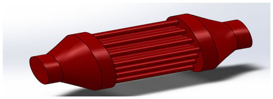
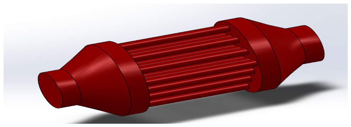
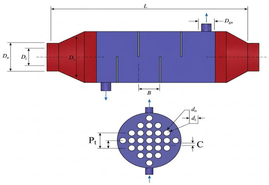
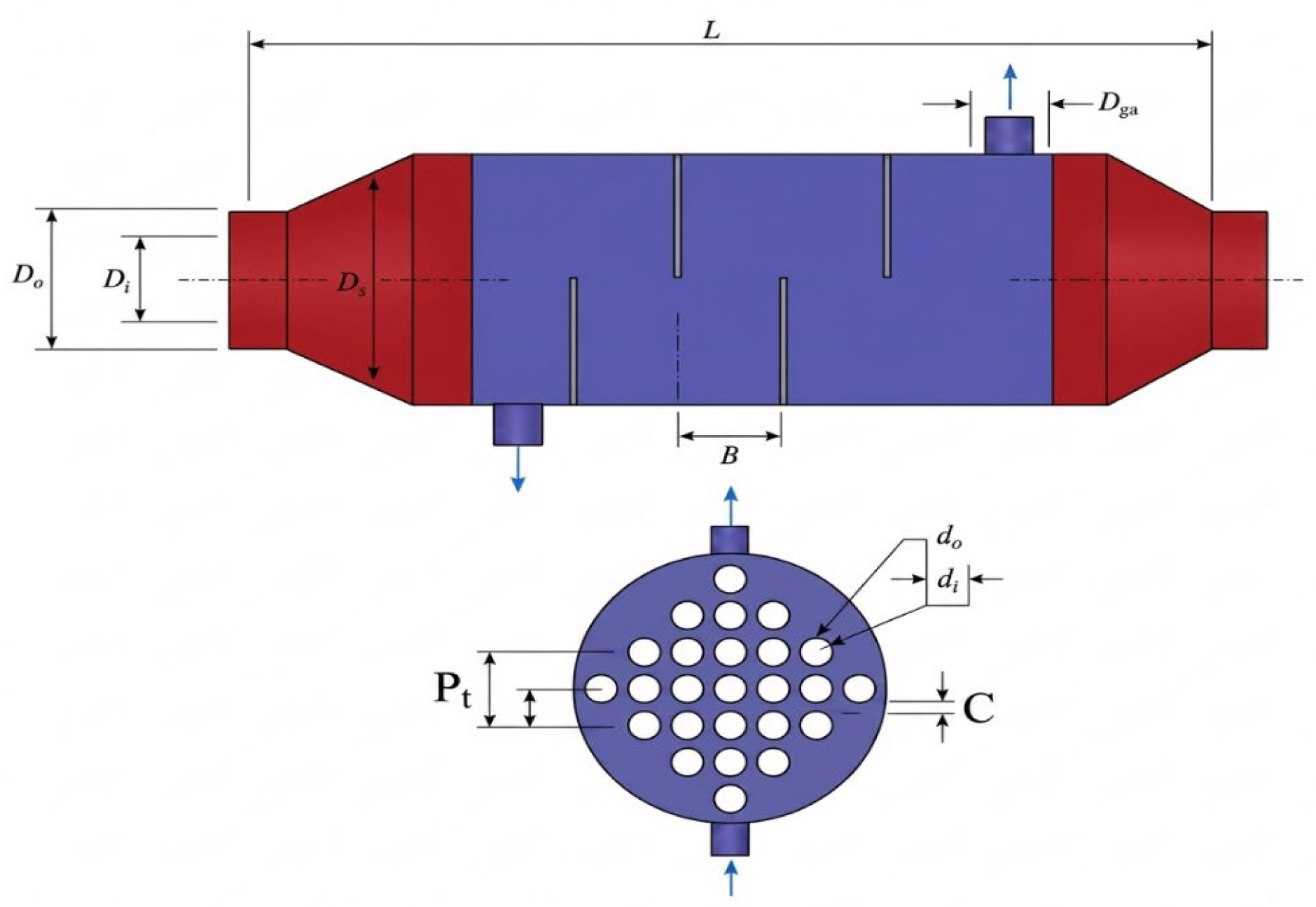
The shell-and-tube heat exchangers were made of stainless steel. The high-temperature molten salt flows outside the tube bundle with 0, 2, 3, or 4 baffles, while the other molten salt flows inside the tube without baffles. The heat exchangers had a total length of 140 cm and an inner shell diameter of 6 cm. They contained 25 tubes, each with a diameter of 6 cm, tube length of 60 cm, and wall thickness of 2.5 mm; the main geometrical characteristics of the heat exchangers are shown in Figure 1 and Figure 2.
Figure 1.
Shell-and-tube heat exchanger geometry, as designed in Solidworks 2023.
Figure 2.
Geometry of shell-and-tube heat exchanger from tube side.
To minimize heat loss, each heat exchanger was assumed to be perfectly insulated and treated as an adiabatic system, and 10 mm thick insulation material was used. In these systems, molten FLiBe salt flows through the tubes and serves as the cold fluid, while molten LiF salt flows outside the tube bundle and serves as the hot fluid. In this study, inlet temperature of molten FliBe salt is 650 °C. While inlet temperature of molten LiF salt is 1000 °C. Dimensions of heat exchanger geometry was given in Table 1.
Table 1.
Dimensions of the designed heat exchanger geometry.
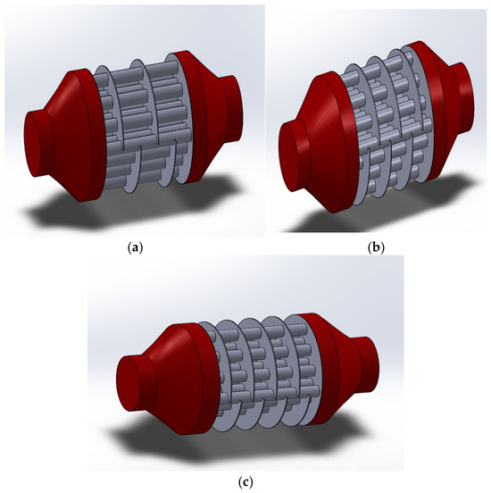
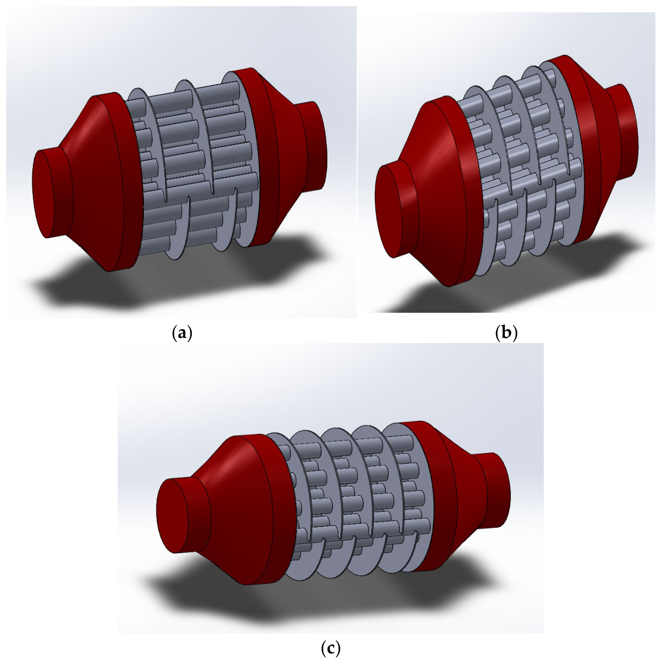
In this study, 4 different shell-and-tube heat exchanger geometries were designed. These geometries had 0, 2,3, and 4 baffles. The different geometries, which were designed in the Solidworks 2023 program, are shown below. Different heat exchanger designs with different baffle numbers were given in Figure 3.
Figure 3.
Heat exchanger designs with different numbers of baffles: (a) 2-row baffle heat exchanger, (b) 3-row baffle heat exchanger, (c) 4-row baffle heat exchanger.
2.2. Data Analysis
Thermophysical properties of various molten salts, that were used in heat exchangers were given in Table 2.
Table 2.
Thermophysical properties of various molten salts [12].
2.3. Governing Equations
In pipe flows, the continuity, momentum and energy equations are given by Equations (1) and (5).
Continuity equation:
Momentum equations:
:
:
:
Energy equations:
2.4. Boundary Conditions
In this study, molten FLiBe salt flows through the tubes and serves as cold fluid, while molten LiF salt flows outside the tube bundle and serve as the hot fluid. The FLiBe salt inlet temperature is 650 °C, while LiF is used as the hot fluid, and its inlet temperature is 1000 °C; the flow is counter-current. Assuming ideal insulation of the heat exchangers, they were treated as adiabatic systems.
2.5. Mesh Selection
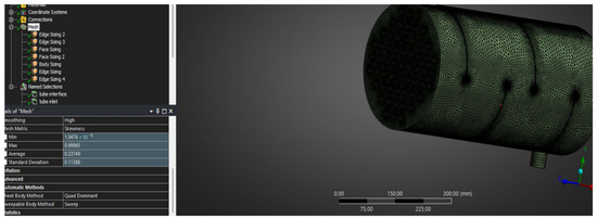
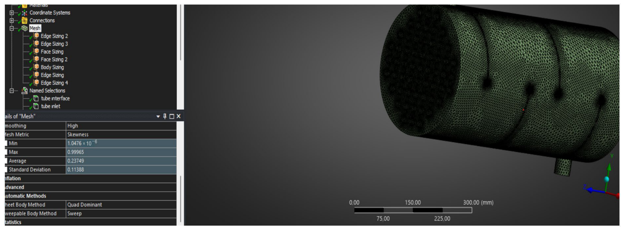
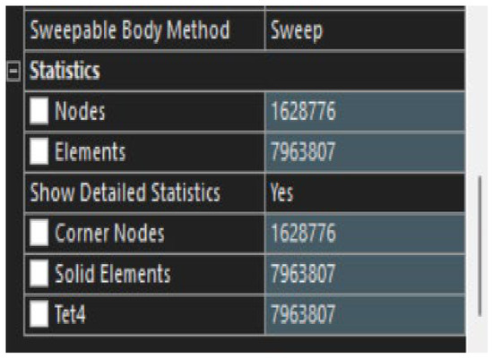
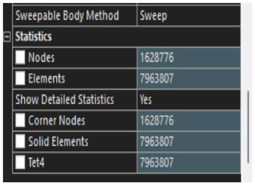
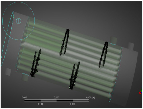
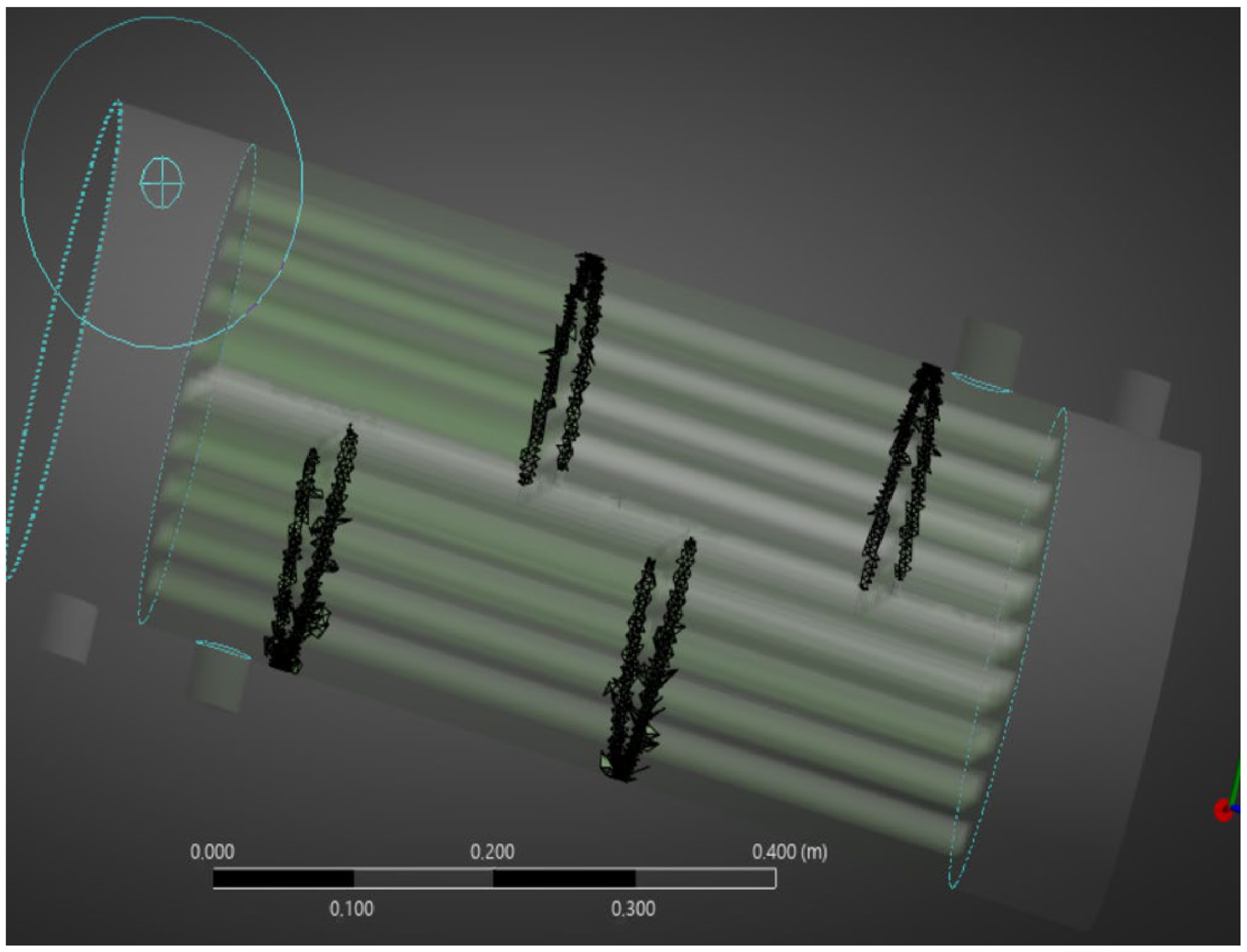
In this study, numerical analysis was performed using five different numerical models. The outlet temperature of the molten salt was taken as the reference point and compared with the experimental results. To ensure the grid independence of the numerical results, a mesh sensitivity analysis was performed using five different models with element counts of 1520400, 3450120, 5810650, 7963807, and 9840300 respectively. The mesh refinement process demonstrated that variations in the monitored physical parameters diminished and reached a stable plateau beyond the model with 7963807 elements. Consequently, the grid configuration with 7963807 elements was selected as the optimal mesh, providing a trade-off between computational accuracy and simulation time. Therefore, all subsequent numerical analyses were performed using this optimal configuration. The mesh structure of heat exchanger geometry was given in Figure 4. And, mesh quality was given in Figure 5 and Figure 6.
Figure 4.
Shell-and-tube heat exchanger after meshing.
Figure 5.
Number of nodes and elements in heat exchanger.
Figure 6.
Problematic meshes over 0.80 skewness.
2.6. Turbulence Model
In this study, the Standard Turbulence Model was selected to model the turbulent flow and thermal behavior within the molten salt shell-and-tube heat exchangers. This two-equation model was chosen for its high stability in capturing main-stream turbulence around complex baffle geometries, its low computational cost providing fast convergence, and its proven reliability in high-temperature molten salt applications across the literature. Furthermore, under the high-Prandtl -number thermophysical conditions of molten salts, it provides an optimal balance between reliable predictions of turbulent heat transfer in the core flow region and reasonable computational time.
3. Results and Discussion
In this study, the hydrodynamic and thermal performance—specifically the heat transfer, pressure drop, Nusselt number, and turbulence levels—of LiF and FLiBe molten salts were comparatively analyzed across four different shell-and-tube heat exchanger geometries: unbaffled, and two, three, and four baffles.
The numerical results demonstrate that increasing the number of baffles significantly enhances the turbulence kinetic energy of the flow, thereby leading to a notable rise in the Nusselt number and total heat transfer. However, this thermal enhancement comes at the expense of a considerable increase in shell-side pressure drop. Across the performance evaluation for both molten salts, the three-baffle geometry provided the most optimal thermohydraulic balance by substantially enhancing heat transfer and turbulent mixing while maintaining the pressure drop within acceptable limits. Regarding the fluid media, FLiBe exhibited superior overall heat transfer values, whereas LiF presented operational cost advantages owing to lower pressure losses.
4. Conclusions
In this study, the thermohydraulic performance of LiF and FLiBe molten salts in shell-and-tube heat exchangers with zero, two, three, and four baffles was numerically investigated. The obtained results indicate that the increased turbulence resulting from a higher baffle count directly enhances heat transfer and Nusselt number, albeit at the cost of an increased shell-side pressure drop. Overall, the three-baffle geometry provided the most optimal thermohydraulic balance, delivering high turbulence and heat transfer alongside an acceptable pressure drop penalty.
Consequently, the followings are obtained:
- Heat Transfer and Nusselt Number: Increasing the baffle count from zero to four enhanced turbulent mixing, resulting in a continuous rise in the Nusselt number and total heat transfer for both LiF and FLiBe.
- Pressure Drop: In parallel with the enhanced heat transfer, the shell-side pressure drop and the required pumping power increased as the number of baffles increased.
- Optimum Geometry Selection: Considering the trade-off between turbulence enhancement and pressure drop penalty, the three-baffle configuration emerged as the optimal design yielding the best thermohydraulic performance.
- Fluid Comparison (LiF vs. FLiBe): FLiBe exhibited superior heat transfer coefficients and Nusselt numbers due to its thermophysical characteristics, whereas LiF demonstrated lower pressure drops, offering operational cost advantages.
Author Contributions
Conceptualization, H.M.Ş. and B.T.; methodology, H.M.Ş. and B.T.; software, B.T.; validation, H.M.Ş. and B.T.; formal analysis, H.M.Ş. and B.T.; investigation, B.T.; resources, H.M.Ş.; data curation, H.M.Ş.; writing—original draft preparation, H.M.Ş.; writing—review and editing, H.M.Ş.; visualization, H.M.Ş.; supervision, H.M.Ş.; project administration, H.M.Ş.; funding acquisition, H.M.Ş. All authors have read and agreed to the published version of the manuscript.
Funding
This research received no external funding.
Institutional Review Board Statement
Not applicable.
Informed Consent Statement
Not applicable.
Data Availability Statement
The data presented in this study are available upon request from the corresponding author.
Conflicts of Interest
The authors declare no conflicts of interest. The funders had no role in the design of the study; in the collection, analyses, or interpretation of data; in the writing of the manuscript; or in the decision to publish the results.
Abbreviations
| CFD | Computational Fluid Dynamics |
| FLiBe | Lithium Fluoride–Beryllium Fluoride (LiF–BeF2) |
| HVAC | Heating, Ventilation, and Air Conditioning |
| LBE | Lead–Bismuth Eutectic |
| STHE | Shell-and-Tube Heat Exchanger |
| PCHE | Printed Compact Heat Exchanger |
| STHE-SB | Shell-and-Tube Heat Exchanger with Segmental Baffles |
| PEC | Performance Evaluation Criterion |
| Re | Reynolds number |
| Nu | Nusselt number |
References
- Du, B.-C.; He, Y.-L.; Wang, K.; Zhu, H.-H. Convective heat transfer of molten salt in the shell-and-tube heat exchanger with segmental baffles. Int. J. Heat Mass Transf. 2017, 113, 456–465. [Google Scholar] [CrossRef] [Scilit]
- Boran, K.; Şahin, H.M.; Daştan, F. Isı Eşanjörlerinde Isı Transferi İyileştirme Yöntemlerinin Sayısal ve Deneysel Olarak İncelenmesi. Politek. Derg. 2014, 17, 185–191. Available online: https://dergipark.org.tr/tr/pub/politeknik/article/368024 (accessed on 26 August 2026).
- Moran, M.J.; Shapiro, H.N. Fundamentals of Engineering Thermodynamics, 5th ed.; John Wiley & Sons: Hoboken, NJ, USA, 2006; p. 308. [Google Scholar]
- Mahmudah, R.; Widiatmono, R.; Darmawan, D. Performance Evaluation of Working Fluids in Shell-and-Tube Heat Exchangers Using OpenFOAM. J. Phys. Conf. Ser. 2025, 3139, 012037. [Google Scholar] [CrossRef] [Scilit]
- Khaliquzzama, M.A.; Masuri, S.U.; Saidur, R.; Hairuddin, A.A.; Tahir, S.M.; Malek, N.A. Heat transfer analysis of molten salt nitrates inside shell and tube heat exchanger with small round holed segmental baffles for concentrated solar power. Int. J. Heat Fluid Flow 2025, 116, 109916. [Google Scholar] [CrossRef] [Scilit]
- Wang, Y.; Lu, Y.; Gao, Q.; Li, F.; Ma, Y.; Wang, Y.; Wu, Y. Numerical Study on Heat Transfer and Frictional Resistance of Two Types of Molten Salts in Straight Channels and Supercritical Carbon Dioxide in Airfoil Channels. J. Therm. Sci. 2024, 33, 1443–1457. [Google Scholar] [CrossRef] [Scilit]
- Hoffman, H.W.; Cohen, S.I. Fused Salt Heat Transfer, Part III: Forced Convection Heat Transfer in Circular Tubes Containing the Salt Mixture NaNO2–KNO3–NaNO3; Report ORNL-2433; Oak Ridge National Laboratory: Oak Ridge, TN, USA, 1960.
- Mohammadzadeh, A.M.; Jafari, B.; Hosseinzadeh, K.; Paikar, E. Numerical investigation of segmental baffle design in shell and tube heat exchangers with varying inclination angles and spacing. Sci. Rep. 2025, 15, 4683. [Google Scholar] [CrossRef] [Scilit] [PubMed]
- Zheng, H.; Fu, D.; Zhang, C.; Han, S.; Niu, J.; Wu, Y. Investigation on heat transfer characteristic of nitrate/nitrite molten salt nanofluids in bidirectional twisted tube. Therm. Sci. Eng. Prog. 2025, 57, 103194. [Google Scholar] [CrossRef] [Scilit]
- He, Y.-L.; Zheng, Z.-J.; Du, B.-C.; Wang, K.; Qiu, Y. Experimental investigation on turbulent heat transfer characteristics of molten salt in a shell-and-tube heat exchanger. Appl. Therm. Eng. 2016, 108, 1206–1213. [Google Scholar] [CrossRef] [Scilit]
- Lu, J.; Shen, X.; Ding, J.; Peng, Q.; Wen, Y. Convective heat transfer of high temperature molten salt in transversely grooved tube. Appl. Therm. Eng. 2013, 61, 157–162. [Google Scholar] [CrossRef] [Scilit]
- Bernagozzi, M.; Panesar, A.S.; Morgan, R. Molten salt selection methodology for medium temperature liquid air energy storage application. Appl. Energy 2019, 248, 500–511. [Google Scholar] [CrossRef] [Scilit]

Disclaimer/Publisher’s Note: The statements, opinions and data contained in all publications are solely those of the individual author(s) and contributor(s) and not of MDPI and/or the editor(s). MDPI and/or the editor(s) disclaim responsibility for any injury to people or property resulting from any ideas, methods, instructions or products referred to in the content. |
© 2026 by the authors. Licensee MDPI, Basel, Switzerland. This article is an open access article distributed under the terms and conditions of the Creative Commons Attribution (CC BY) license.