


Abstract
This study examines an inverter converter as an element of the digital twin of the energy-technological subsystem of a bakery production line. Based on the structural design and the schematic electrical diagram, a structural–functional analysis of the device was carried out, the main energy conversion units were identified, and their role in ensuring the stable operation of the actuating mechanisms of the technological line was demonstrated. In the calculation mode, the PWM switching frequency is assumed to be 50 kHz, the equivalent primary voltage of the switching stage is ±20 V, the average rectified output voltage is 14.8–15.0 V, and the load current range is 0.1–3.0 A. Within the digital twin framework, the inverter unit is represented as an observable energy object for which the input voltage, load current, PWM signal duty cycle, switching frequency, and temperature of the power elements are taken into account. The output parameters include the output voltage, ripple amplitude, loss level, thermal state, and overload indicators. It is shown that when the load current increases from 0.1 A to 3.0 A, the output voltage decreases from 15.00 V to 14.15 V, while the maximum efficiency reaches 91.5% at a load of approximately 2.0 A. After applying an LC filter, the average output voltage changes from 15.2 V to 14.8 V, while the ripple amplitude decreases from 5.0 Vpp to 0.45 Vpp, i.e., by approximately 11 times, and the relative ripple is reduced from 33% to 3.0%.
1. Introduction
Modern inverter converters and PWM-controlled DC/AC structures remain one of the key areas of power electronics, as they determine the quality of the output voltage, the level of harmonic distortion, energy efficiency, and the stability of operation of both autonomous and grid-connected power supply systems. In recent years, particular attention has been paid to predictive and robust control of inverters with LC and LCL filters, as well as to the problem of accurate reference signal tracking under conditions of parametric uncertainty and varying load [1,2,3,4].
For bakery production lines operating within digital manufacturing environments, the importance of such units increases significantly, since the stability of the power supply directly affects the operation of conveyor drives, fans, pumps, feeding systems, and other actuating mechanisms. A separate block of contemporary research is associated with the improvement of modulation methods, reduction in harmonic components, adaptive damping, and enhancement of the stability of output characteristics, which is particularly important when integrating power electronics into observable and predictable energy subsystems [5,6,7,8,9,10].
Despite the considerable number of publications, engineering practice still requires an analysis of specific circuit implementations in which a device is examined simultaneously from both structural design and schematic electrical perspectives. In [11], a dispatch-control method based on electrical-load forecasting using a deep neural network is proposed. In [12], the main parameters of a solar collector with thermosiphon circulation and its potential application in combined heat and power supply systems are investigated. A mathematical analysis of the heat transfer process in the storage tank is performed, and the dependence of the thermophysical properties of the heat carrier on temperature is established, which is important for improving the overall energy efficiency of the system.
In the present work, the inverter converter is considered not as an isolated power unit, but as an element of the digital twin of the energy-technological subsystem of a bakery production line. This approach makes it possible to relate real hardware units performing inversion, transformation, rectification, filtering, and regulation functions with their digital representation, as well as to use the converter parameters for subsequent digital monitoring, diagnostics, and prediction of operating modes.
2. Methodology
The research methodology is based on structural–functional analysis of an inverter converter and its representation within the digital twin of the energy-technological subsystem of a bread-baking production line. In the first stage, the device’s structural and electrical schematic diagrams were used to identify the principal energy conversion units, including the input stage, PWM control, power switching block, transformer, rectifier, and LC filter. In the second stage, a computational model was developed for the inverter unit, establishing relationships between input parameters, load conditions, and output characteristics required for digital monitoring and diagnostics. Subsequently, illustrative graphs and tables were constructed based on the adopted computational parameters, reflecting variations in output voltage, efficiency, and ripple levels across different operating modes.
Within the digital twin architecture of the bread-baking line, the inverter converter is treated as a discrete energy object interconnected with actuating and auxiliary mechanisms. Its model must capture both the internal electrical processes of the device and the influence of the conversion regime on the operation of process equipment. At the digital twin level, the input parameters of such an object comprise input voltage, load current, PWM duty cycle, switching frequency, and power-element temperature. The output parameters include output voltage, ripple amplitude, loss level, thermal state, and overload indicators. Consequently, the inverter functions not merely as a power supply unit, but as an element of a digital platform that provides diagnostically significant information for real-time line monitoring. This representation is of particular importance in bread-baking production, where supply voltage fluctuations and unstable operating regimes of actuating units can lead to disruption of the technological cycle, temperature deviations, reduced process uniformity, and deterioration of product quality.
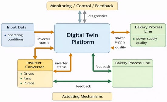
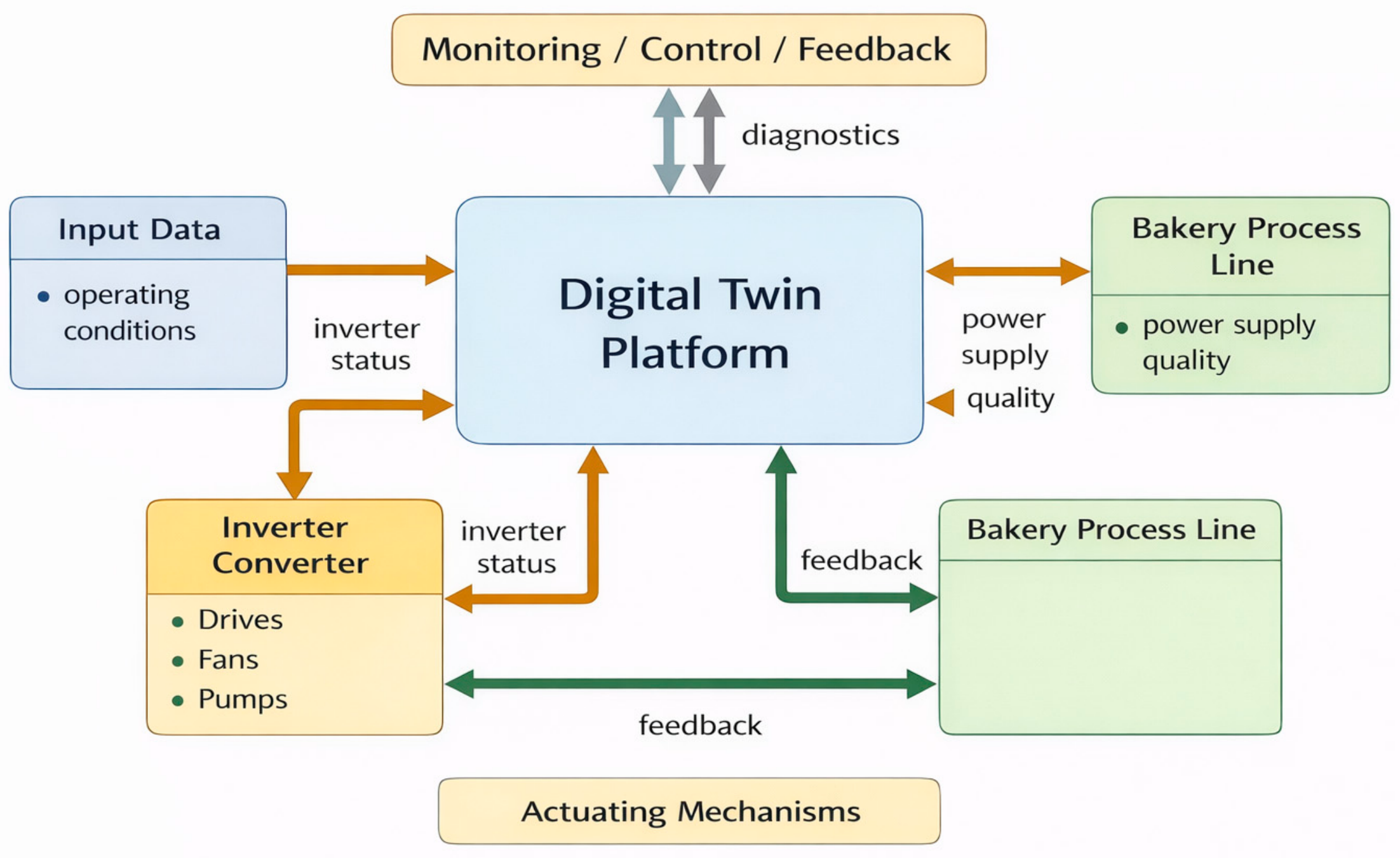
Figure 1 presents the integration scheme of the inverter converter within the digital twin of the bread-baking line. The central element is the digital twin platform, which receives input data on the system state, processes information on inverter operation, and interacts with the process line and actuating mechanisms. Within this structure, the inverter converter serves as the linking element between the power supply and the operation of drives, fans, and pumps. This diagram demonstrates that the inverter is not an isolated electronic unit, but an integral component of a unified monitoring, control, and feedback loop in bread-baking production.
Figure 1.
Block diagram of the inverter converter as an element of the digital twin of the energy-technological subsystem of the bread-baking line.
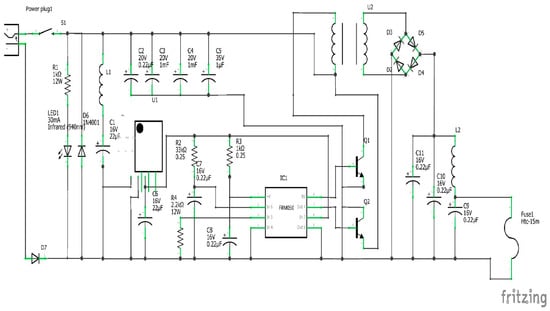
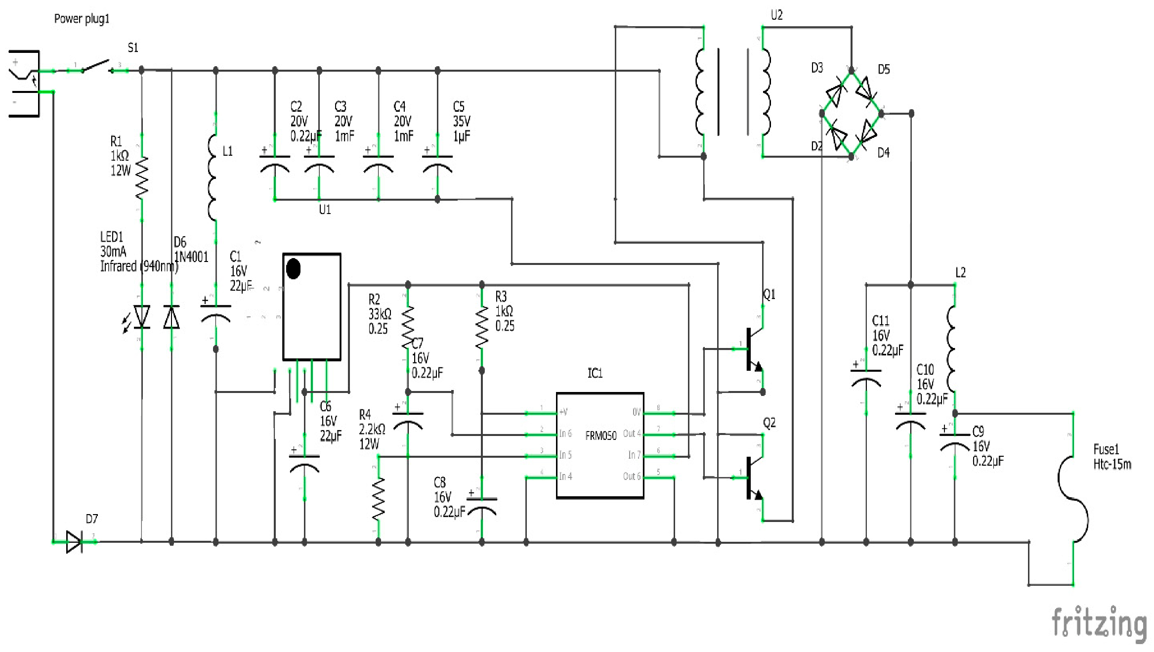
The electrical schematic diagram (Figure 2) reflects the interconnections between the power input connector, switching circuitry, indication circuits, inductors, storage capacitors, the driver/PWM controller, power switches, transformer, diode bridge, and output filter. The presence of a rectifier bridge and filter on the output side indicates that the energy, following high-frequency conversion, is restored to a smoothed form suitable for load supply.
Figure 2.
Electrical schematic diagram of the inverter converter under investigation.
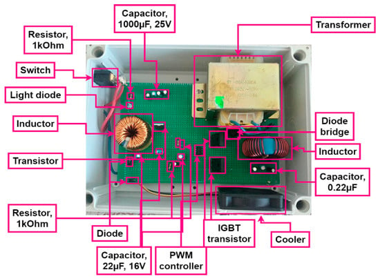
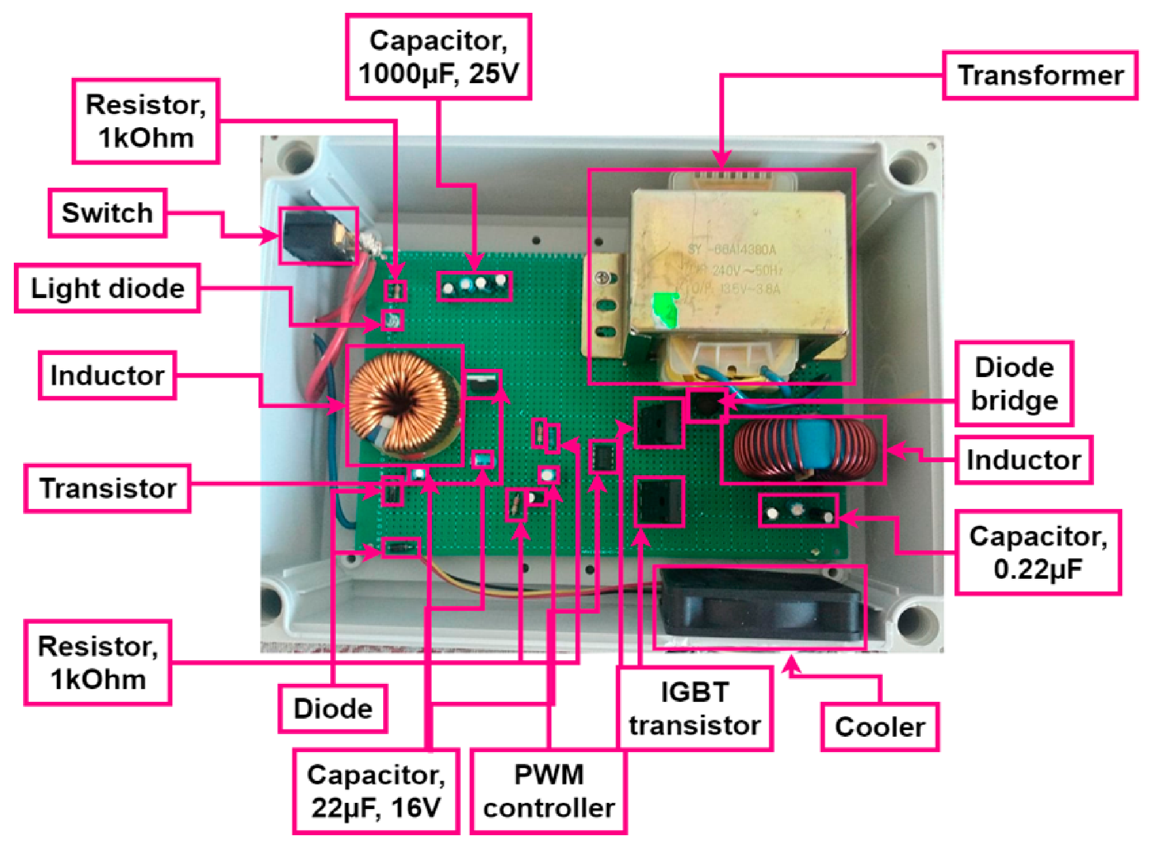
Figure 3 illustrates the hardware implementation of the inverter converter, in which power and auxiliary components are identified: resistors, LED indicators, inductive elements, power transistors, an IGBT transistor, rectifier diodes, a PWM controller, capacitors of various capacitances, a transformer, a diode bridge, and a heat sink. This component arrangement is indicative of the compact layout characteristic of switch-mode power supplies and inverter modules.
Figure 3.
Hardware implementation of the inverter converter.
The operation of the circuit shown in Figure 3 can be described as a sequence of interrelated stages. Upon voltage application, energy enters the input stage, where switching, primary smoothing, and the establishment of stable operating conditions for the controller are performed. The PWM controller subsequently generates pulse control signals for the power switches, which convert the input energy into a high-frequency form. The high-frequency signal is applied to the primary winding of the transformer. The transformer fulfills three principal functions: voltage level conversion, energy transfer at elevated frequency, and galvanic isolation between the input and output sections of the circuit. On the secondary side, the rectifier bridge produces a unipolar voltage, after which the LC filter attenuates residual ripple.
Accordingly, the device comprises the following functional units: input stage and switching circuitry; PWM control; power switching stage; high-frequency transformer; secondary rectifier; and smoothing filter and output stage. It is precisely this architecture that ensures the combination of regulation capability, compactness, and energy efficiency.
Since the source materials include circuit diagrams but do not contain a set of experimental oscillograms or a complete component parameter datasheet, a typical operating regime characteristic of a low-to-medium power switch-mode inverter converter was adopted for graph construction. These parameters are employed exclusively for illustrative purposes to demonstrate the circuit’s behavior and do not represent the finalized measured characteristics of the device.
3. Results
As a result of the structural–functional and computational analysis of the inverter converter, dependencies characterizing its operation as part of the digital twin of the energy-technological subsystem of the bread-baking production line were obtained.
Table 1 presents the initial parameters adopted for the construction of the computational graphs of the inverter converter. A PWM switching frequency of 50 kHz and an equivalent primary voltage of the power switching stage of ±20 V were selected as the baseline operating regime, corresponding to the nominal computational model of inverter operation. Under the adopted conditions, the mean rectified output voltage is approximately 14.8–15.0 V, and the analysis was performed over a load current range of 0.1 to 3.0 A.
Table 1.
Adopted assumptions for the construction of computational graphs.
Table 2 presents the variation in the output parameters of the inverter converter as the load current increases from 0.1 to 3.0 A. Under light load conditions of 0.1 A, the output voltage is 15.00 V, the output power is 1.50 W, and the efficiency stands at 66.0%, corresponding to the initial operating regime. As the load increases to 1.0–1.5 A, the converter enters the region of stable operation: at 1.0 A, values of 14.85 V and 88.0% are obtained, while at 1.5 A the corresponding figures are 14.75 V, 22.13 W, and 90.0%. Maximum efficiency is observed at a load current of approximately 2.0 A, where at an output voltage of 14.60 V and an output power of 29.20 W, the efficiency reaches 91.5%. With a further increase in load to 2.5–3.0 A, the output voltage decreases to 14.40–14.15 V and efficiency drops to 91.0–89.0%, indicating growing losses in the power conversion path.
Table 2.
Computed output parameters of the converter as a function of load current.
Table 3 illustrates the effect of the LC filter on the output voltage quality of the inverter converter. Prior to the filter, the mean voltage after the rectifier is 15.2 V; following the LC filter, it decreases to 14.8 V, which is attributable to minor losses in the filter components. Concurrently, the ripple amplitude is reduced from 5.0 V_pp to 0.45 V_pp, representing an approximately elevenfold attenuation, while the relative ripple decreases from 33% to 3.0%. As a result, the signal character transitions from pulsating to smoothed, which substantially enhances the suitability of the output voltage for stable load supply.
Table 3.
Comparison of computed voltage characteristics before and after the LC filter.
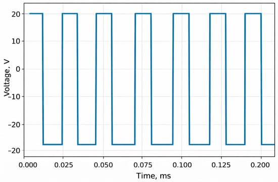
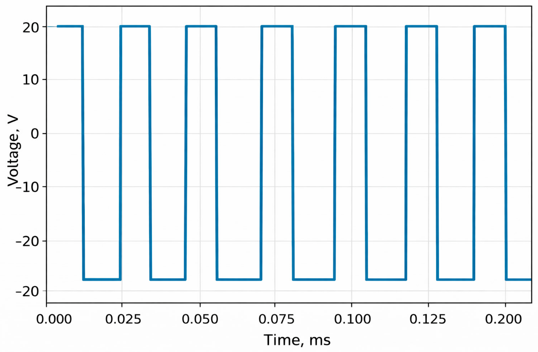
Figure 4 presents the computed waveform of the equivalent primary voltage in PWM mode, depicting a rectangular voltage signal varying within a range of approximately −20 V to +20 V. Over the time interval from 0 to 0.20 ms, approximately 10 switching cycles are observed, corresponding to a frequency on the order of 50 kHz. The signal exhibits a nearly symmetric form with respect to the zero level, with an amplitude of approximately 20 V in each half-period. This voltage waveform is characteristic of the inverter switching stage prior to subsequent filtering or rectification.
Figure 4.
Computed waveform of the equivalent primary voltage in PWM mode.
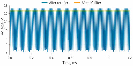
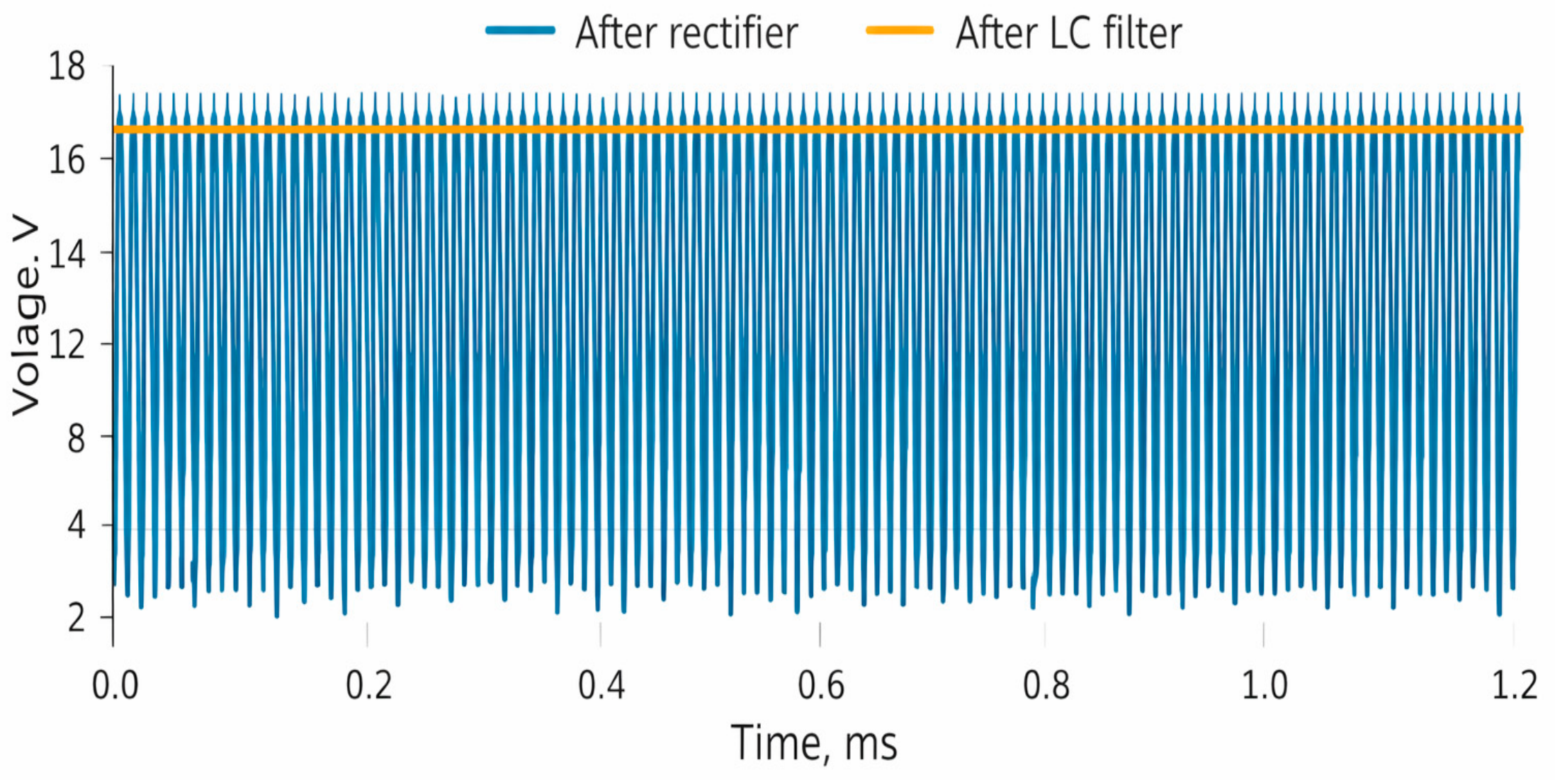
Figure 5 presents a comparison of the output voltage waveforms after the rectifier and after the LC filter. The blue curve representing the post-rectifier signal exhibits pronounced pulsations ranging from approximately 0–1 V to 16 V, whereas the orange curve representing the post-filter signal stabilizes at approximately 14.8 V. Over the interval of 0–1.2 ms, it is evident that the LC filter effectively eliminates high-frequency oscillations and produces a substantially smoother voltage for the load. Thus, the graph confirms that filtering markedly improves the quality of the output signal and significantly reduces ripple amplitude.
Figure 5.
Computed comparison of voltage waveforms after the rectifier and after the LC filter.
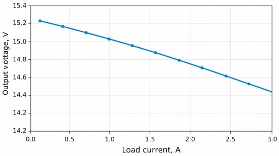
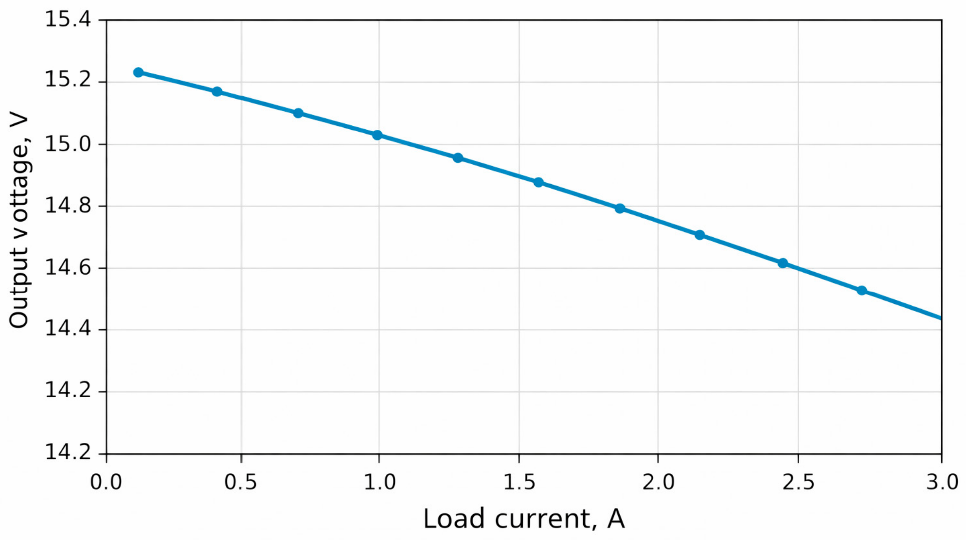
Figure 6 presents the dependence of output voltage on load current over the range of 0.1–3.0 A. As the load current increases, the output voltage decreases gradually from approximately 15.23 V to 14.57 V, representing a total voltage drop of approximately 0.66 V. In the range of 1.0–2.0 A, the voltage variation is relatively minor—from approximately 15.05 V to 14.78 V—indicating a sufficiently stable operating regime of the converter. With a further increase in load to 2.5–3.0 A, the voltage drop becomes more pronounced, which is attributable to increasing losses in the power stage and output circuit.
Figure 6.
Computed dependence of output voltage on load current.
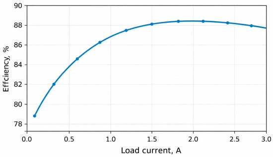
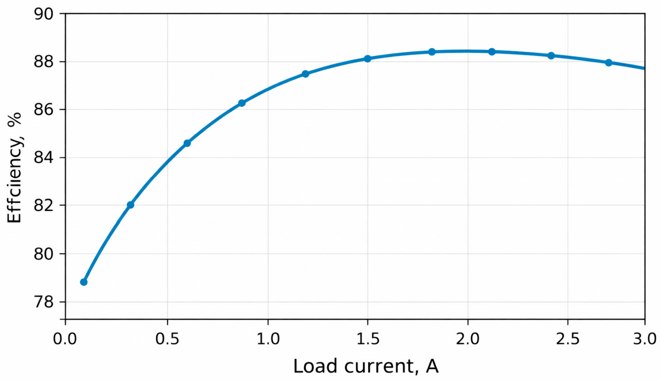
Figure 7 presents the dependence of the inverter converter efficiency on load current over the range of 0.1–3.0 A. Under light load conditions of 0.1 A, the efficiency is approximately 78%; it then increases rapidly with rising current, reaching approximately 82% at 0.4 A, 86.7% at 1.0 A, and 88.4% at 1.5 A. Maximum efficiency is observed in the region of 1.8–2.2 A, where it reaches approximately 88.7–88.8%. With a further increase in load to 2.5–3.0 A, efficiency decreases slightly to 88.5–88.0%, indicating growing losses in the power components under elevated load conditions.
Figure 7.
Computed dependence of converter efficiency on load current.
4. Conclusions
This study presents a structural–functional analysis of an inverter converter and demonstrates the feasibility of its representation as an element of the digital twin of the energy-technological subsystem of a bread-baking production line. On the basis of the structural and electrical schematic diagrams, it has been established that this unit performs not only functions of electrical energy conversion and stabilization, but may also be regarded as an observable object within a digital monitoring framework, characterized by a set of informative input, output, and diagnostic parameters. It has been shown that the inverter converter maintains stable operation across the investigated load range, and that the application of filtering substantially improves the quality of the output signal, enhancing the suitability of the converted voltage for supplying the actuating mechanisms of the bread-baking line. The practical significance of this work lies in the fact that the parameters of the inverter unit can be incorporated into the digital twin of the bread-baking production facility for the purposes of monitoring, diagnostics, energy efficiency assessment, and early detection of equipment deviations. Further research should be directed toward experimental verification of the model, expansion of the diagnostic feature set, and integration of the inverter converter into the comprehensive digital control platform of the bread-baking production line.
Author Contributions
Conceptualization, G.A. and M.K.; methodology, G.A. and B.A.; software, M.K.; validation, G.A., B.A. and N.Y.; formal analysis, G.A. and M.K.; investigation, G.A. and B.A.; resources, M.K. and N.Y.; data curation, B.A.; writing—original draft preparation, G.A.; writing—review and editing, G.A., B.A. and N.Y.; visualization, M.K. and B.A.; supervision, M.K.; project administration, G.A.; funding acquisition, N.Y. All authors have read and agreed to the published version of the manuscript.
Funding
This research was funded by the Science Committee of the Ministry of Science and Higher Education of the Republic of Kazakhstan (Grant No. BR24992975). The authors would also like to express their sincere gratitude to the industrial partner for providing access to the equipment and for their support in collecting the real-time sensor data.
Institutional Review Board Statement
Not applicable.
Informed Consent Statement
Not applicable.
Data Availability Statement
The data presented in this study are available on request from the corresponding author. The data are not publicly available due to the computational and illustrative nature of the results.
Acknowledgments
The authors express their gratitude to the editorial board and reviewers for their valuable comments and suggestions. No generative AI tools were used in the preparation of this manuscript.
Conflicts of Interest
The authors declare no conflicts of interest.
Abbreviations
The following abbreviations are used in this manuscript:
| PWM | Pulse-Width Modulation |
| LC | Inductor–Capacitor (filter) |
| IGBT | Insulated Gate Bipolar Transistor |
| DC | Direct Current |
| AC | Alternating Current |
| LCL | Inductor–Capacitor–Inductor (filter) |
| LED | Light-Emitting Diode |
| MPC | Model Predictive Control |
| PV | Photovoltaic |
References
- Andrea, C.Q.; Batista, E.A.; Pereira, L.F.d.S.C.; de Brito, M.A.G.; de Souza, G.V. LMI-Based MPC Design Applied to the Single-Phase PWM Inverter with LC Filter under Uncertain Parameters. Sensors 2024, 24, 4325. [Google Scholar] [CrossRef] [Scilit] [PubMed]
- Bushra, E.; Zeb, K.; Ahmad, I.; Khalid, M. A comprehensive review on recent trends and future prospects of PWM techniques for harmonic suppression in renewable energies based power converters. Results Eng. 2024, 22, 102213. [Google Scholar] [CrossRef] [Scilit]
- Al-Abri, S.; Shadoul, M.; Yousef, H.; Al-Abri, R. Optimal tracking for PV three-phase grid-connected inverter with LC filter. Frankl. Open 2024, 8, 100133. [Google Scholar] [CrossRef] [Scilit]
- Hossain, M.T.; Hossen, M.Z.; Badal, F.R.; Islam, M.R.; Hasan, M.M.; Ali, M.F.; Ahamed, M.H.; Abhi, S.H.; Islam, M.M.; Sarker, S.K.; et al. Next generation power inverter for grid resilience: Technology review. Heliyon 2024, 10, e39596. [Google Scholar] [CrossRef] [Scilit] [PubMed]
- Hoang, Q.-M.; Nguyễn, B.-H.; Vo-Duy, T.; Trovão, J.P.F.; Ta, M.C. Decoupled average model-based sliding mode current control of LC-filtered inverters in rotating frame. Math. Comput. Simul. 2024, 224, 148–164. [Google Scholar] [CrossRef] [Scilit]
- Liu, E.; Han, Y.; Zalhaf, A.S.; Yang, P.; Wang, C. Performance evaluation of isolated three-phase voltage source inverter with LC filter adopting different MPC methods under various types of load. Control Eng. Pract. 2023, 135, 105520. [Google Scholar] [CrossRef] [Scilit]
- Khan, D.; Qais, M.H.; Hasanien, H.; Alghuwainem, S.; Sami, I.; Hu, P. Enhanced stability of grid-connected inverter using adaptive filtering damping of capacitive current feedback of LCL filter. Ain Shams Eng. J. 2025, 16, 103465. [Google Scholar] [CrossRef] [Scilit]
- Hoyos, F.E.; Candelo-Becerra, J.E.; Rincón, A. Enhanced Three-Phase Inverter Control: Robust Sliding Mode Control with Washout Filter for Low Harmonics. Energies 2025, 18, 5889. [Google Scholar] [CrossRef] [Scilit]
- Sun, Z.; Chen, L.; Ding, J.; Liu, X. Research on Generalized Average Modeling and Characteristic Harmonic Frequency Configuration Strategy for PWM Inverter Using Modelica. Electronics 2025, 14, 3685. [Google Scholar] [CrossRef] [Scilit]
- Taha, T.A.; Shalaby, M.; Abdul Wahab, N.I.; Zaynal, H.I.; Hassan, M.K.; Al-Sowayan, S.; Alawad, M.A. Recent Advancements in Multilevel Inverters: Topologies, Modulation Techniques, and Emerging Applications. Symmetry 2025, 17, 1010. [Google Scholar] [CrossRef] [Scilit]
- Kalantayevskaya, N.; Koshekov, K.; Latypov, S.; Savostin, A.; Kunelbayev, M. Design of decision-making support system in power grid dispatch control based on the forecasting of energy consumption. Cogent Eng. 2022, 9, 2026554. [Google Scholar] [CrossRef] [Scilit]
- Amirgaliyev, Y.; Kunelbayev, M.; Amirgaliyev, B.; Kalizhanova, A.; Kozbakova, A.; Merembayev, T.; Dassibekov, A. Mathematical justification of thermosyphon effect main parameters for solar heating system. Cogent Eng. 2020, 7, 1851629. [Google Scholar] [CrossRef] [Scilit]

Disclaimer/Publisher’s Note: The statements, opinions and data contained in all publications are solely those of the individual author(s) and contributor(s) and not of MDPI and/or the editor(s). MDPI and/or the editor(s) disclaim responsibility for any injury to people or property resulting from any ideas, methods, instructions or products referred to in the content. |
© 2026 by the authors. Licensee MDPI, Basel, Switzerland. This article is an open access article distributed under the terms and conditions of the Creative Commons Attribution (CC BY) license.