


Abstract
An uninterruptible power supply (UPS) system delivers continuous power during outages, protecting equipment, data, and stability. It uses solar-charged lead–acid batteries as backup, with field programmable gate array (FPGA) controlling charging/discharging via relay switches. It also features free renewable energy, scalability, compact design, and easy maintenance.
1. Introduction
In today’s rapidly advancing technological and industrial landscape, the demand for continuous and stable power supply has grown significantly, as reliable electricity is the cornerstone of industrial operations, commercial activities, and daily life [1]. However, alongside increasing energy consumption and mounting environmental challenges, it is essential to consider how to maintain power supply stability while simultaneously achieving energy sustainability and environmental protection. In response, uninterruptible power systems (UPSs) have emerged as a key solution, enabling the protection of critical systems and equipment from damage and ensuring continuous power delivery during grid outages.
Taiwan has long faced a chronic power shortage, relying heavily on imported energy sources, which account for 98% of its supply. In 2022, thermal power generation remained dominant, contributing 82.42% of total output, with coal at 42.07%, natural gas at 38.81%, and fuel oil at 1.54%. Despite this reliance, the available capacity remains insufficient to meet the demands of Taiwan’s economic development. Renewable energy accounted for only 8.27% of total generation, led by photovoltaics at 3.70%, followed by hydropower at 2.03%, waste-to-energy at 1.25%, wind power at 1.23%, biomass at 0.05%, and geothermal at 0.01% [2]. Climate scientists have warned that global greenhouse gas emissions must reach net zero by 2050 to avoid catastrophic impacts. Fossil fuel-based thermal plants not only emit large amounts of carbon dioxide but also produce harmful PM2.5 particles, posing serious environmental challenges for Taiwan. Diversifying energy sources has therefore become both necessary and strategically urgent [3].
A typical uninterruptible power system operates by detecting battery voltage, monitoring the utility grid through an FPGA, and determining whether solar charging is available. A relay network then manages battery charging and discharging based on these inputs. Traditionally, control strategies have been implemented using microcontrollers or microprocessors. However, such systems suffer from limited I/O pins, restricted parallel processing, and complex logical design, making it difficult to execute multiple fast and independent control tasks simultaneously. In contrast, we developed a digital control architecture for an uninterruptible power system using a field programmable gate array (FPGA) chip integrated with energy storage batteries. This approach addresses Taiwan’s grid stability and power shortage challenges by replacing conventional microcontroller-based control with FPGA-based design [4,5,6,7,8]. The proposed system overcomes the limitations of single-task microcontrollers and significantly enhances system integration, offering a more robust solution for future energy resilience.
2. Materials and Methods
2.1. Method
Referring to the technology disclosed in Taiwan Invention Patent No. I840223, entitled Charging and discharging control system and method, we adopted a charging and discharging control system and its associated method [9]. The system architecture comprises a power conversion device, an energy storage device, and a control unit. The system provides three major functions: real-time monitoring, intelligent scheduling, and protection mechanisms. The control unit receives operating parameters from both the power conversion device and the energy storage device, such as voltage, current, temperature, and the state of charge (SOC) of the battery. For intelligent scheduling, the control unit automatically switches between charging mode and discharging mode according to the predefined power demand and the real-time battery status, achieving optimal energy utilization efficiency. Regarding the protection mechanism, the system incorporates overcharge, over-discharge, and over-temperature protection to ensure safety during the charging and discharging processes and to prolong the overall service life of the system.
2.2. FPGA
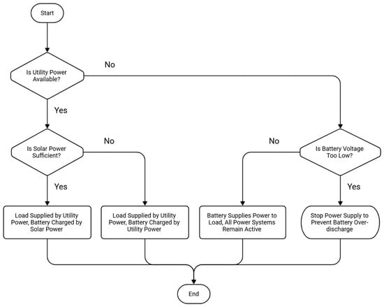
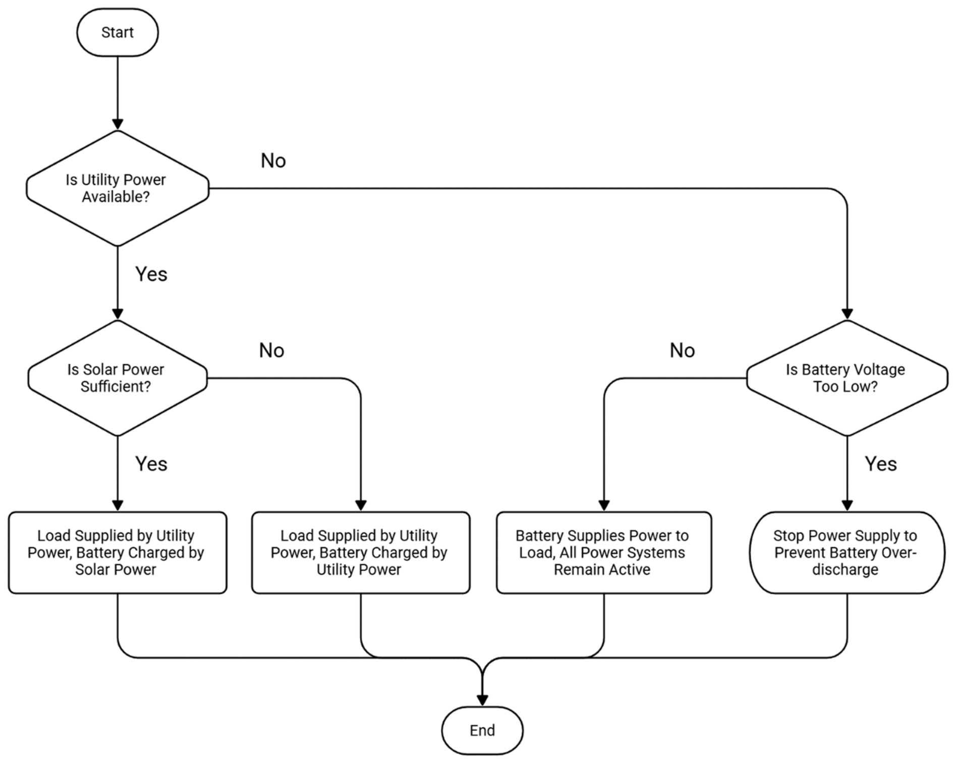
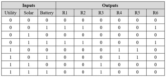
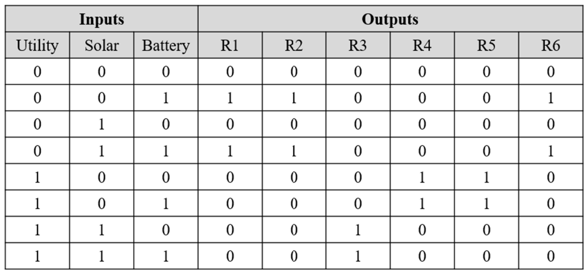
The control flow of the uninterruptible power system design is shown in Figure 1. A truth table is implemented in the FPGA program (Quartus (Quartus Prime 18.1) Lite Edition), which determines the output pin states based on voltage variations at the input pins, thereby controlling the relay switches as summarized in Figure 2. Once the system is activated, it first checks whether the utility grid is available.
Figure 1.
Flowchart of UPS control system.
Figure 2.
UPS control logic truth table.
If utility power is present, the system evaluates whether the solar input meets the charging conditions. When the solar voltage is sufficient, the load is supplied by the grid while the solar energy charges the battery. If the solar voltage is insufficient, the grid still supplies the load, but the battery is charged from the grid instead. If the system detects that the utility power is absent, it enters the backup power supply mode. In this mode, it checks whether the battery voltage is too low. If the battery voltage is within the normal operating range, the battery supplies power to the load and maintains system operation. Conversely, if the battery voltage falls below a predefined threshold, the system shuts down the output to prevent excessive discharge and potential damage to the battery. Through the above control flow, the developed system automatically switches the power source under different supply conditions and ensures that the battery operates within a safe voltage range, thereby enhancing the overall stability and reliability of the uninterruptible power solution.
2.3. System Control
Regarding utility power detection, when FPGA senses an input voltage of 3.3 V, the system defines utility power as present; when the input is 0 V, utility power is regarded as interrupted (AC = 0). Once the utility power is absent, the system immediately activates the backup power supply mode, switching relays R1 and R2 to the inverter side (normally open, NO) and turning on R6 so that the battery supplies power to the load through the inverter, thereby ensuring uninterrupted power delivery.
When utility power is present (AC = 1), the system further evaluates the solar voltage. If the solar voltage is higher than 20 V, it is defined as Solar = 1, indicating that the solar source has sufficient charging capability. If the voltage is lower than 12 V, it is defined as Solar = 0. When the voltage falls between 12 V and 20 V, the system maintains its previous state to avoid frequent switching near the threshold region. This dual threshold hysteresis control mechanism effectively improves system stability.
For battery voltage detection, the system uses the open circuit voltage of a lead–acid battery as the reference. When the battery voltage lies between 12.6 V and 12.8 V, it is defined as Battery = 1, indicating that the battery is close to a fully charged state; otherwise, it is defined as Battery = 0. This binary determination serves as the basis for enabling or disabling the charging control logic. In the charging control section, the system simultaneously considers the battery voltage and the relay states. When Solar = 1 and the battery voltage is insufficient (Battery = 0), the system prioritizes solar charging by turning on R3 and switching R5 to the solar charging path. If Solar = 0 and Battery = 0, the system activates grid-based charging by turning on R4 and switching R5 to the utility charging source.
Moreover, during the charging process, the battery voltage temporarily increases to the range of 12.6 to 12.8 V without necessarily indicating a fully charged state. To avoid premature termination of charging, the system uses the states of R3 and R4 to identify the actual charging source. When R3 = 1, solar charging is active; when R4 = 1, grid-based charging is active. This auxiliary judgment mechanism prevents the system from incorrectly treating the battery as fully charged and halting the charging process prematurely.
The system integrates all detection results and controls the states of relays R1–R6 according to the truth table, realizing multiple operating modes such as grid-based power supply, solar charging, grid-based charging, and battery backup power supply. Through the above control logic, the developed system can automatically switch to the most appropriate power supply mode under different source conditions, improving the stability, reliability, and energy utilization efficiency of the uninterruptible power system. From the combined truth table, the system’s control logic can be classified into three main operating modes. When the utility power is absent, but the battery is capable of supplying power, the system enters the battery supply mode. Second, when utility power is available, but the solar input is insufficient, the system enters the grid supply mode with grid-based charging. Third, when both utility power and solar energy are available and sufficient, the system enters the grid supply mode with solar charging. If none of the available power sources meet the required conditions, the system turns off the output to protect connected equipment and prevent abnormal operation.
3. Conclusions
UPS controllers are implemented using dedicated microprocessors or microcontrollers. Their main drawback lies in excessive system size, since additional circuit boards, batteries, power converters, and related components are required to ensure stable operation. In contrast, this study successfully demonstrates an industrial-grade UPS architecture using an FPGA chip, achieving high performance and ease of maintenance. By adopting a non-traditional design flow that moves directly from system simulation to hardware description code generation, the proposed approach enables seamless implementation as well as straightforward debugging and verification, thereby reducing firmware development time and associated costs.
The FPGA chip functions in a multiprocessor-like manner and offers superior parallel processing capability, making it highly suitable for future upgrades. Additional green energy functions can be incrementally integrated into the UPS control logic without degrading overall chip performance. Conventional microprocessors or microcontrollers, by comparison, are less capable of accommodating multiple complex functions within a single platform. Under high computational loads, they are prone to overheating, reduced stability, and even data loss. The FPGA-based solution effectively overcomes these limitations, aligning with the industrial trend toward flexible and integrable chip designs that can be adapted to diverse control requirements and algorithmic tasks.
Author Contributions
Conceptualization, Y.-Y.L.; methodology, B.-T.Y.; software, B.-T.Y. and R.-H.H.; validation and formal analysis, Y.-Y.L.; resources, Y.-Y.L.; data curation, B.-T.Y.; writing—original draft preparation, Y.-Y.L. and B.-T.Y.; writing—review and editing, Y.-Y.L.; funding acquisition, Y.-Y.L. All authors have read and agreed to the published version of the manuscript.
Funding
This research was funded by the National Science and Technology Council, Taiwan, under the research grants 113-2813-C-269-003-E.
Institutional Review Board Statement
Not applicable.
Informed Consent Statement
Not applicable.
Data Availability Statement
No new data were generated or analyzed. All relevant information is included in the article.
Conflicts of Interest
The authors declare no conflict of interest.
Abbreviations
The following abbreviations are used in this manuscript:
| UPS | Uninterruptible Power Supply |
| FPGA | Field-ProgrammableGateArray |
| SOC | State of Charge |
References
- International Energy Agency (IEA). Energy Sankey: Chinese Taipei Energy Balance 2020. Available online: https://www.iea.org/data-and-statistics/data-tools/energy-sankey (accessed on 20 April 2026).
- Bureau of Energy, MOEA. Handbook 2023; Bureau of Energy, MOEA: Taipei, Taiwan, 2024; pp. 46–47.
- Academia Sinica. Appendix 1B: Global Trends in Promoting Net Zero. In Taiwan Net Zero Technology R&D Policy Recommendations; Academia Sinica Report No. 17; Academia Sinica: Taipei, Taiwan, 2022; pp. 384–390. [Google Scholar]
- Rubaai, A.; Kotaru, R. Neural Net-Based Robust Controller Design for Brushless DC Motor Drives. IEEE Trans. Syst. Man Cybern. C Appl. Rev. 1999, 29, 460–474. [Google Scholar] [CrossRef] [Scilit]
- Choi, S.-H.; Ko, J.-S.; Kim, I.-D.; Park, J.-S.; Hong, S.-C. Precise position control using a PMSM with a disturbance observer containing a system parameter compensator. IEE Proc.—Electr. Power Appl. 2005, 152, 1573–1577. [Google Scholar] [CrossRef] [Scilit]
- Monmasson, E.; Cirstea, M. FPGA design methodology for industrial control systems—A review. IEEE Trans. Ind. Electron. 2007, 54, 1824–1842. [Google Scholar] [CrossRef] [Scilit]
- Ricci, F.; Le-Huy, H. An FPGA-based rapid prototyping platform for variable-speed drives. In Proceedings of the IEEE 2002 28th Annual Conference of the Industrial Electronics Society IECON’02, Sevilla, Spain, 5–8 November 2002. [Google Scholar]
- Su, Z.; Khorasani, K. A neural-network-based controller for a single-link flexible manipulator using the inverse dynamics approach. IEEE Trans. Ind. Electron. 2001, 48, 1074–1086. [Google Scholar] [CrossRef] [Scilit]
- Shieh, C.-S.; Ye, B.-T.; Hong, R.-H. System and Method for Controlling Charging and Discharging. Patent No. I840223, 21 April 2024. [Google Scholar]
Disclaimer/Publisher’s Note: The statements, opinions and data contained in all publications are solely those of the individual author(s) and contributor(s) and not of MDPI and/or the editor(s). MDPI and/or the editor(s) disclaim responsibility for any injury to people or property resulting from any ideas, methods, instructions or products referred to in the content. |
© 2026 by the authors. Licensee MDPI, Basel, Switzerland. This article is an open access article distributed under the terms and conditions of the Creative Commons Attribution (CC BY) license.