


Abstract
Trajectory tracking is a fundamental requirement for omnidirectional mobile robots operating in autonomous navigation and service applications. Although conventional proportional–derivative (PD) controllers are widely used because of their simplicity, their tracking performance may deteriorate during large trajectory deviations. This paper presents and experimentally evaluates a nonlinear proportional–derivative (NL-PD) controller that adaptively increases the proportional and derivative actions according to the tracking error while preserving the simplicity of the classical PD structure. The paper also investigates a hybrid controller that combines nonlinear position control with conventional PD orientation control. The proposed controllers are implemented on a DJI RoboMaster EP omnidirectional mobile robot using a real-time experimental framework based on MATLAB/Simulink 2026a, Python 3.7.8, and the RoboMaster Software Development Kit (SDK 0.1.1.68). Their performance is evaluated using circular, lemniscate, and square reference trajectories and compared through reaching time, root mean square error, maximum tracking error, and integral absolute error. Experimental results show that the nonlinear strategies consistently improve trajectory tracking compared with the conventional PD controller, while the fully nonlinear controller achieves the best overall performance for trajectories involving significant curvature variations.
1. Introduction
Trajectory tracking is a fundamental problem in mobile robotics because it directly determines the ability of autonomous platforms to accurately follow predefined paths under modeling uncertainties and external disturbances [1,2]. This challenge is particularly relevant for omnidirectional robots equipped with Mecanum wheels, whose holonomic kinematics provide high maneuverability but increase controller-design complexity [3,4]. Classical proportional–derivative (PD) controllers remain attractive because of their simplicity and low computational cost, whereas more advanced approaches, including sliding mode, model predictive, adaptive, fuzzy, and neural-network-based controllers, generally provide improved tracking performance at the expense of higher computational complexity, accurate models, or extensive parameter tuning [5].
An attractive alternative is to introduce nonlinear characteristics into conventional PD controllers while preserving their simple structure [6]. By adapting the proportional and derivative actions according to the tracking error, nonlinear PD controllers provide stronger corrective actions during large deviations while maintaining smooth behavior near the desired trajectory [7]. However, their experimental evaluation on omnidirectional mobile robots remains limited.
This paper experimentally evaluates nonlinear PD trajectory tracking controllers implemented on a RoboMaster EP omnidirectional mobile robot. A fully nonlinear controller and a hybrid strategy combining nonlinear position control with conventional PD orientation control are investigated and compared with a conventional PD controller.
The main contributions of this work are:
- Development of a nonlinear PD trajectory tracking controller with error-dependent proportional and derivative gains.
- Development of a modular real-time framework that integrates MATLAB/Simulink, Python, and the RoboMaster SDK.
- Experimental comparison of conventional PD, nonlinear PD, and hybrid controllers.
- Experimental validation using circular, lemniscate, and square trajectories with quantitative performance tracking metrics.
2. RoboMaster Kinematic Modeling
2.1. RoboMaster EP Platform
The experimental platform is the DJI RoboMaster EP, an omnidirectional mobile robot with four independently actuated Mecanum wheels that enable holonomic motion. Its open SDK provides external control and access to odometry and sensor data through Python [8,9]. MATLAB/Simulink performs trajectory generation, control, and kinematic computations, while Python interfaces with the RoboMaster SDK, allowing different controllers to be evaluated within the same communication architecture.
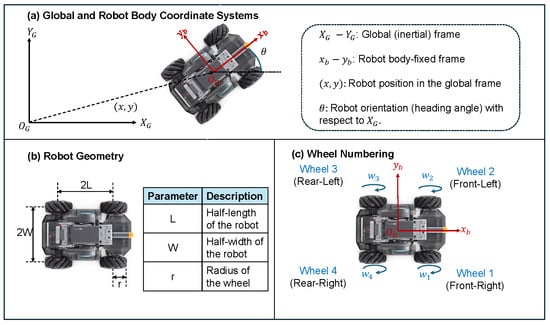
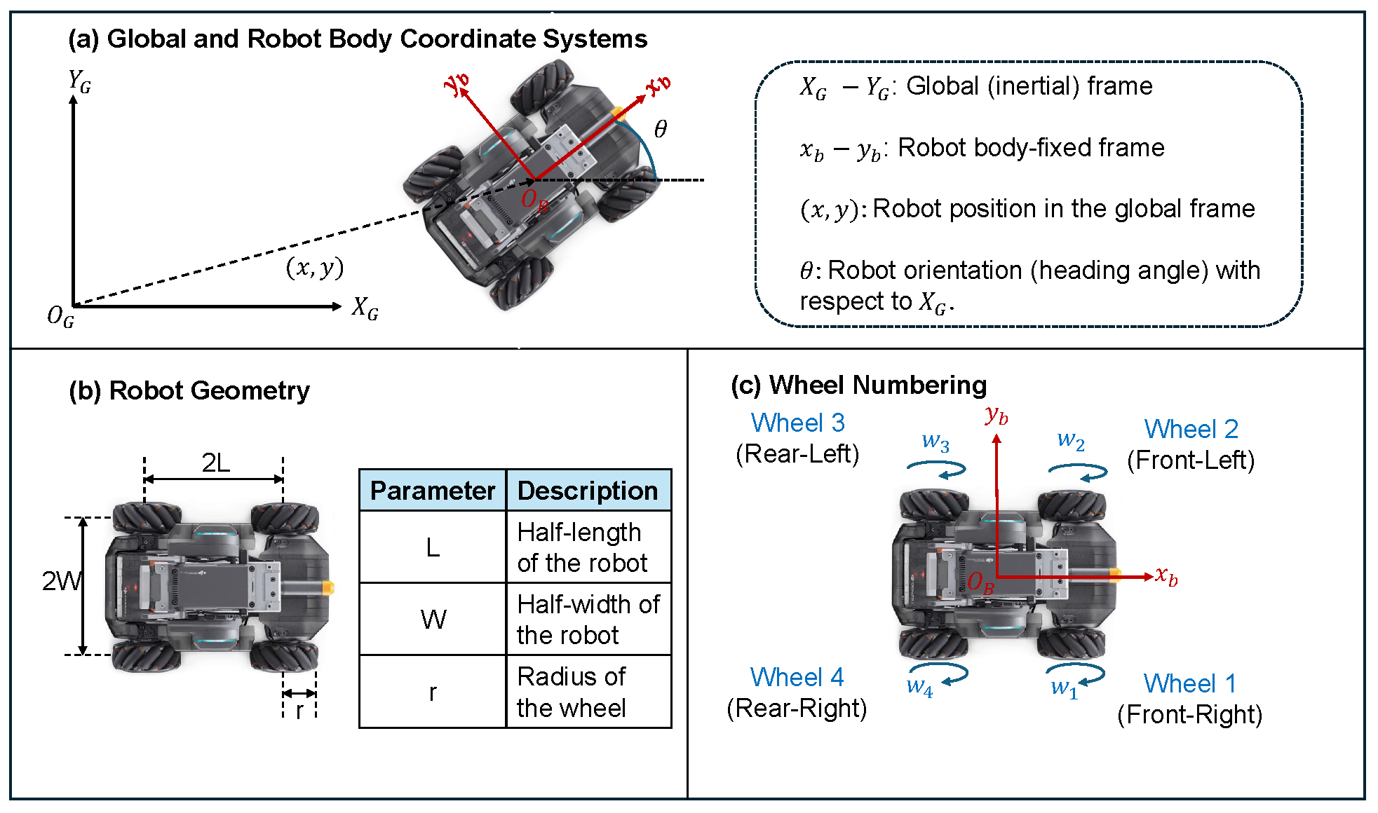
Figure 1 illustrates the RoboMaster EP platform together with the adopted coordinate systems, geometric parameters, and the wheel-numbering convention.
Figure 1.
RoboMaster EP platform showing the adopted coordinate systems, geometric parameters, and wheel-numbering convention.
2.2. Coordinate Systems
The RoboMaster EP motion is described using a global reference frame, , and a body-fixed reference frame, . The robot pose is defined as , where x, y, and denote the position and heading angle. The body velocity vector is , where , , and are the longitudinal, lateral, and angular velocities. Trajectory tracking is performed in the global frame, whereas the control commands are computed in the body-fixed frame.
2.3. Kinematic Model
The direct kinematic model relates the angular velocities of the four Mecanum wheels to the translational and rotational velocities of the robot chassis expressed in the body-fixed reference frame.
Let denote the angular velocity vector of the wheel. Taking into account the radius of the wheel r, the half-length L, and the half-width W shown in Figure 1, the fixed body velocity vector is obtained from the standard kinematic model of a four-wheel Mecanum robot [10] as
The corresponding body-fixed velocity vector is obtained from the global reference frame as
During trajectory tracking, the controller computes the desired robot velocities in the global reference frame. These velocities are transformed into the body-fixed velocity vector using (2) and subsequently converted into individual wheel angular velocities using the standard inverse kinematic model of the Mecanum platform [10]. The resulting wheel velocities are transmitted to the RoboMaster EP through the communication architecture described in the following section.
3. Experimental Platform and Communication Architecture
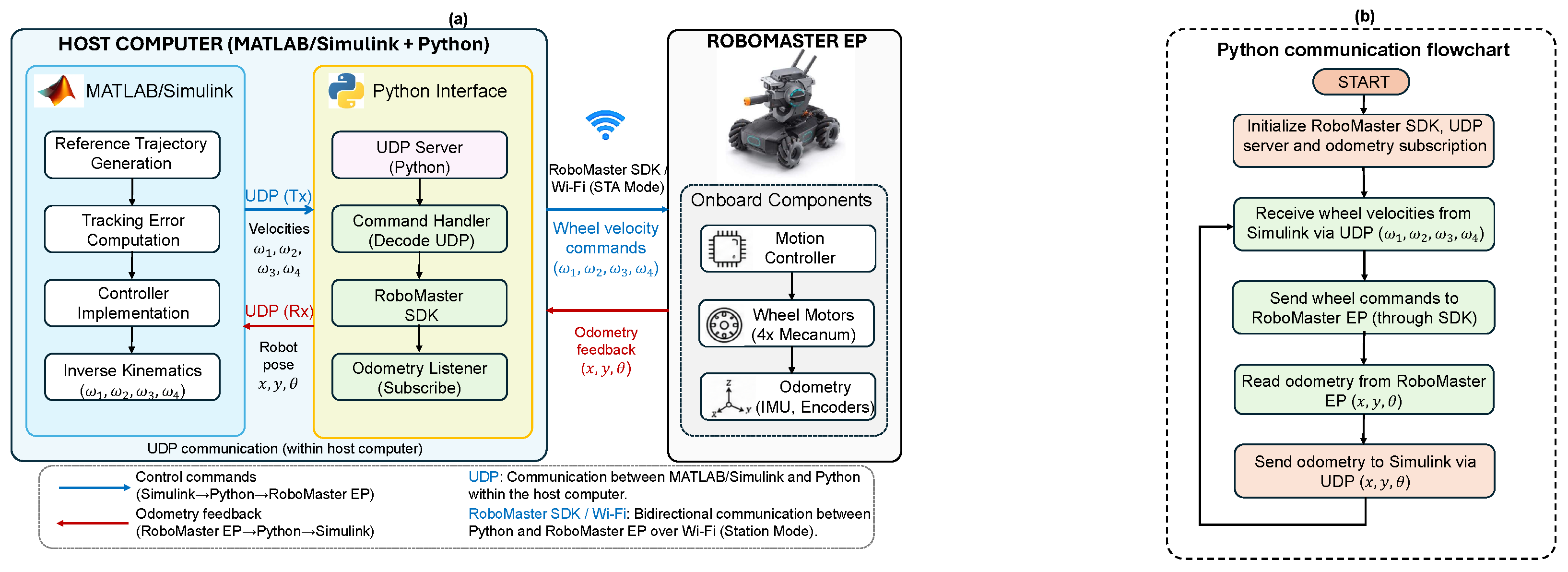
To experimentally validate the proposed trajectory tracking controllers, a modular communication architecture was developed to integrate MATLAB/Simulink, Python, and the RoboMaster EP into a unified real-time control system. The main objective of this architecture is to decouple the trajectory tracking algorithm from the robot-specific communication procedures, allowing different control strategies to be implemented in Simulink without modifying the communication software. The overall architecture is illustrated in Figure 2.
Figure 2.
Experimental communication system: (a) architecture between MATLAB/Simulink, Python, and the RoboMaster EP; (b) Python communication flowchart.
The experimental platform consists of two physical entities: a host computer and a RoboMaster EP mobile robot. MATLAB/Simulink and Python are executed on the host computer, whereas the RoboMaster EP performs the physical motion and continuously provides odometry information for closed-loop control.
3.1. Host Computer
MATLAB/Simulink and Python are executed simultaneously on the host computer at a sampling frequency of 50 Hz (20 ms). Simulink implements the complete trajectory tracking algorithm, while Python provides the communication interface with the RoboMaster SDK. Both applications exchange data through the UDP User Datagram Protocol over the local loopback interface, where Simulink transmits the angular velocity commands of the wheel , and Python returns the measured robot pose . Python forwards wheel commands to the RoboMaster EP via Wi-Fi and relays the measured odometry back to Simulink, providing a modular real-time communication framework with negligible latency.
3.2. RoboMaster EP
The RoboMaster EP receives wheel angular velocity commands through its onboard motion controller and independently drives the four Mecanum wheels. Similarly, the onboard odometry system estimates the robot pose and transmits it back to the host computer through the RoboMaster SDK. This bidirectional communication framework enables experimental real-time validation of different trajectory-tracking controllers while preserving a modular software architecture.
4. Trajectory Tracking Control Architecture
The trajectory tracking system in MATLAB/Simulink uses a modular architecture to evaluate various trajectory generators and control algorithms while maintaining the same communication interface with the RoboMaster EP.
At each sampling instant, Simulink generates the reference trajectory, computes the tracking errors from the robot odometry, evaluates the selected controller, and converts the resulting chassis velocities into wheel angular velocities through the inverse kinematic model. The computed wheel velocities are then transmitted to the RoboMaster EP system via the communication architecture described in Section 3.
4.1. Trajectory Generation
Three reference trajectories were considered for experimental validation: circular, lemniscate, and square trajectories. The trajectory generator provides the desired pose, , together with the corresponding reference velocity vector, .
These trajectories represent increasing levels of motion complexity, from smooth continuous motion to trajectories with higher path curvature variations.
4.2. Tracking Error Computation
The tracking errors are computed as
To avoid discontinuities caused by transitions between and , an angle-unwrapping algorithm is applied before computing the derivative of the orientation error.
4.3. Trajectory Tracking Controller
The conventional PD controller is defined as
The NL-PD controller introduces error-dependent gains, and . Substitution into (4) yields
where and are nonlinear gains that increase the control action for large tracking errors while preserving approximately linear behavior near the equilibrium point.
The controller computes the desired body-fixed velocity vector , which is converted into wheel angular velocities using the inverse kinematic model presented in Section 2.
5. Experimental Results
5.1. Experimental Setup
All experiments were conducted with a sampling period of 20 ms on a flat wooden floor. The RoboMaster EP, with dimensions m and radius mecanum wheels m, started from the initial pose . The position controller parameters were set to , , , and , while the orientation controller employed , , , and . The circular trajectory was defined by a radius of m and a linear velocity of m/s, the lemniscate by an amplitude of m and a period of s, and the square by a side length of m, a corner radius of m, and a period of s. The controller parameters were determined by trial-and-error tuning and remained unchanged throughout all experiments.
5.2. Performance Metrics
Tracking performance was evaluated using three commonly adopted metrics computed from tracking error e, where for position and for orientation; see Table 1. Position and orientation errors are defined as
Table 1.
Performance metrics.
5.3. Circular Trajectory
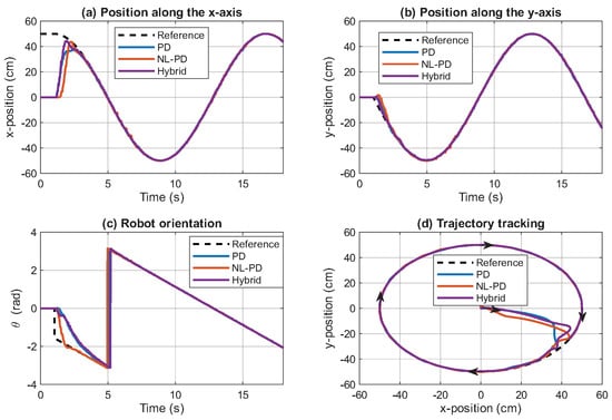
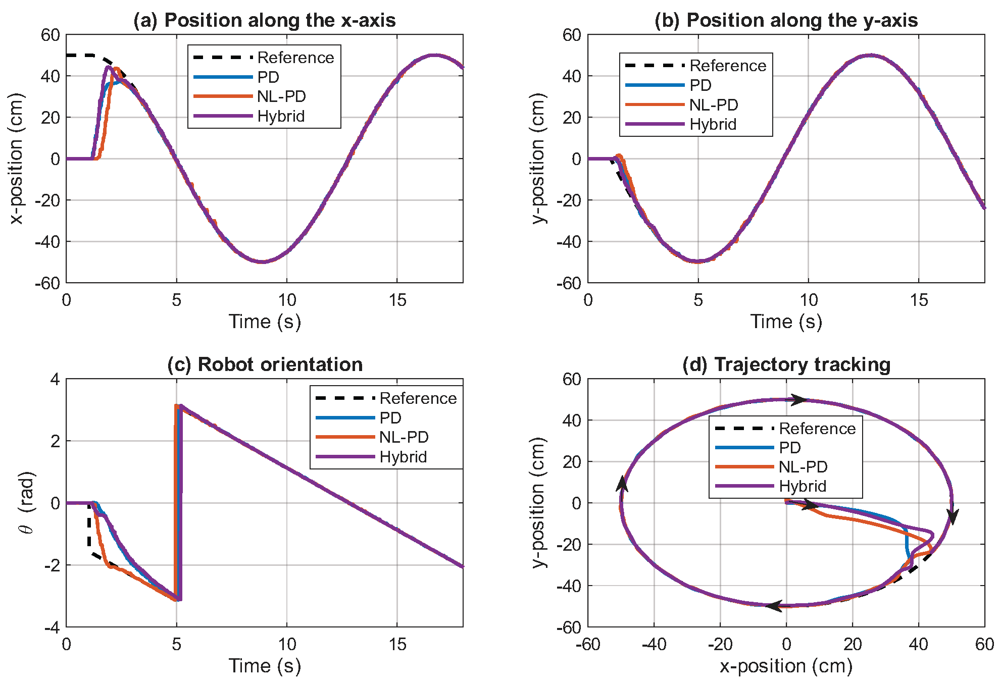
Three trajectory tracking controllers were experimentally evaluated using a circular reference trajectory: a conventional proportional-derivative (PD) controller applied to position (x, y) and orientation (), a nonlinear proportional-derivative (NL-PD) controller applied to the three control loops, and a hybrid controller employing the NL-PD strategy for position coordinates (x, y) while maintaining a conventional PD controller for orientation (). The circular trajectory, characterized by constant curvature and smooth motion, provides a representative benchmark for assessing both the transient response and steady-state tracking performance. The experimental results are presented in Figure 3, while the corresponding quantitative performance metrics are summarized in Table 2.
Figure 3.
Circular trajectory tracking using the PD, NL-PD, and Hybrid controllers.
Table 2.
Performance comparison of the evaluated controllers for the three reference trajectories.
Figure 3a,b show that the three controllers successfully tracked the circular reference in both Cartesian coordinates after a short transient period. The NL-PD and Hybrid controllers exhibited a faster convergence than the conventional PD controller, reducing the initial position error during the trajectory acquisition stage. Once the robot reached the desired path, all controllers maintained stable tracking with only minor deviations.
The orientation responses shown in Figure 3c indicate that the three controllers accurately followed the desired heading angle throughout the experiment. Although the NL-PD controller achieved the shortest reaching time (RT), the Hybrid controller produced the smallest orientation tracking error after convergence. The corresponding trajectory in the plane, presented in Figure 3d, confirms that the Hybrid controller remained closest to the reference path, particularly during the initial transient where the largest deviations occurred.
The results in Table 2 confirm that the Hybrid controller achieved the lowest RMSE, MAXE, and IAE for both position and orientation, whereas NL-PD provided the shortest reaching times. Overall, the hybrid approach offered the best trade-off between transient response and tracking accuracy.
5.4. Lemniscate Trajectory
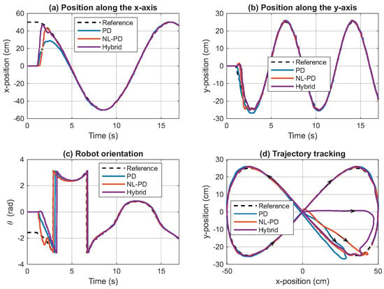
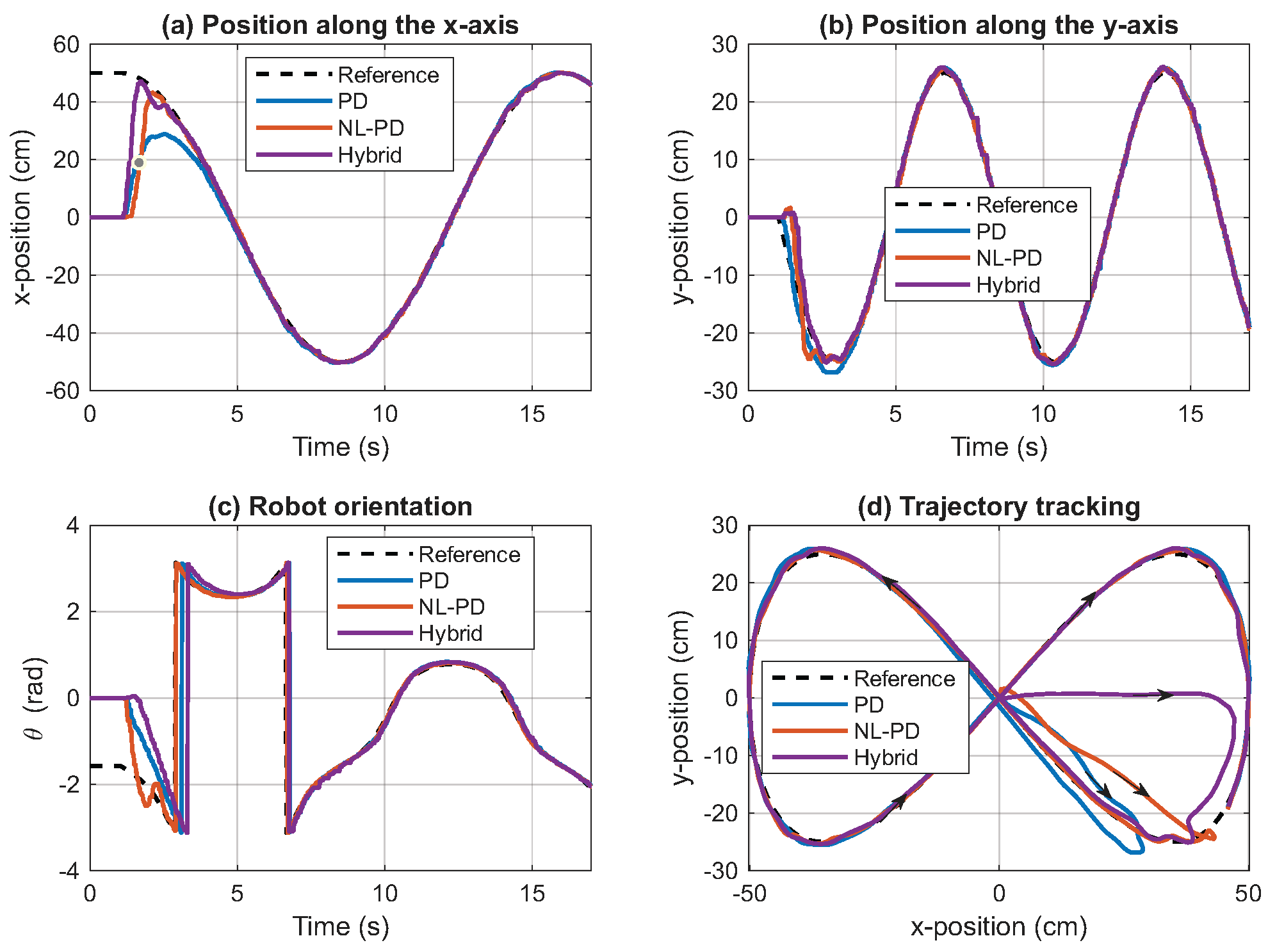
The lemniscate trajectory represents a more challenging tracking task due to its continuously varying curvature and self-intersection. Figure 4 shows that all controllers successfully followed the reference trajectory; however, greater deviations were observed during the rapid changes in direction around the intersection region. Compared with the PD and Hybrid controllers, the NL-PD controller exhibited faster convergence and smaller tracking errors in both position and orientation. As confirmed by the quantitative results summarized in Table 2, the NL-PD controller achieved the lowest reaching time, RMSE, MAXE, and IAE, demonstrating that the nonlinear control law is more effective for trajectories with continuously varying curvature.
Figure 4.
Lemniscate trajectory tracking using the PD, NL-PD, and Hybrid controllers.
5.5. Square Trajectory
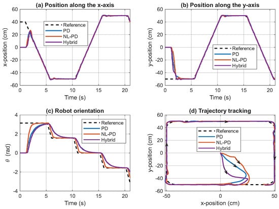
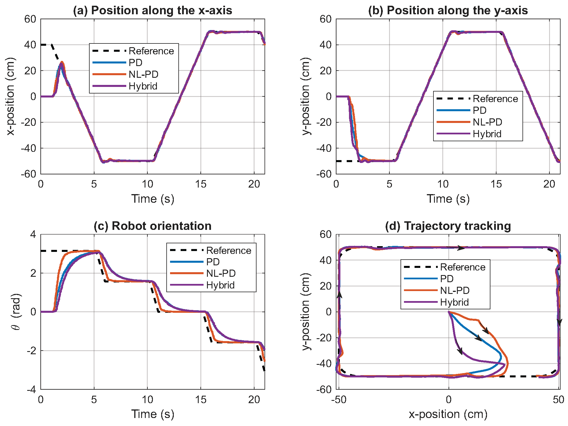
The square trajectory with rounded corners ( m) evaluates controller performance under successive changes in motion direction. As shown in Figure 5, all controllers completed the trajectory, although tracking errors increased near the corners. Overall, the NL-PD controller achieved the best performance, obtaining the lowest RMSE and IAE for position and the lowest reaching time, RMSE, MAXE, and IAE for orientation, whereas the Hybrid controller provided the shortest reaching time for position.
Figure 5.
Square trajectory tracking using the PD, NL-PD, and Hybrid controllers.
6. Conclusions
This paper presented the experimental evaluation of nonlinear PD trajectory tracking controllers for a RoboMaster EP omnidirectional mobile robot. Experimental results obtained with circular, lemniscate, and square trajectories demonstrated that incorporating error-dependent nonlinear gains consistently improves tracking performance over a conventional PD controller. The hybrid controller achieved the best compromise between transient response and tracking accuracy for smooth trajectories, whereas the fully nonlinear controller provided superior performance for trajectories with significant curvature variations. These results indicate that the proposed nonlinear strategy preserves the simplicity and low computational cost of the classical PD controller while enhancing trajectory tracking performance in real-time applications. Future work will focus on stability analysis, robustness evaluation under disturbances, and the extension of the proposed approach to adaptive and predictive control strategies.
Author Contributions
Conceptualization, L.C., D.B. and O.C.; methodology, L.C., D.B. and O.C.; validation, L.C., D.B. and O.C.; investigation, L.C., D.B. and O.C.; writing—original draft preparation, L.C., D.B. and O.C.; writing—review and editing, L.C., D.B. and O.C.; supervision, D.B. and O.C.; All authors have read and agreed to the published version of the manuscript.
Funding
This work was supported by Universidad San Francisco de Quito through the Poli-Grants Program under Grant Nos. 41983 and 42995.
Institutional Review Board Statement
Not applicable.
Informed Consent Statement
Not applicable.
Data Availability Statement
Data are available upon request from the authors.
Conflicts of Interest
The authors declare no conflicts of interest.
References
- Sun, Z.; Hu, S.; He, D.; Zhu, W.; Xie, H.; Zheng, J. Trajectory-tracking control of Mecanum-wheeled omnidirectional mobile robots using adaptive integral terminal sliding mode. Comput. Electr. Eng. 2021, 96, 107500. [Google Scholar] [CrossRef] [Scilit]
- Chen, Y.H. Nonlinear adaptive optimal control design and implementation for trajectory tracking of four-wheeled mecanum mobile robots. Mathematics 2024, 12, 4013. [Google Scholar] [CrossRef] [Scilit]
- Medina, L.; Guerra, G.; Herrera, M.; Guevara, L.; Camacho, O. Trajectory tracking for non-holonomic mobile robots: A comparison of sliding mode control approaches. Results Eng. 2024, 22, 102105. [Google Scholar] [CrossRef] [Scilit]
- Vega, S.; Vasquez-Guevara, M.; Proaño, P.; Andaluz, G.; Leica, P.; Camacho, O. Experimental Comparison of Model-Based and Model-Free Trajectory Tracking Control on a Mobile Robot. Eng 2026, 7, 281. [Google Scholar] [CrossRef] [Scilit]
- Wang, D.; Gao, Y.; Wei, W.; Yu, Q.; Wei, Y.; Li, W.; Fan, Z. Sliding mode observer-based model predictive tracking control for Mecanum-wheeled mobile robot. ISA Trans. 2024, 151, 51–61. [Google Scholar] [CrossRef] [Scilit] [PubMed]
- Cruz-Zavala, E.; Nuno, E.; Moreno, J.A. Robust trajectory-tracking in finite-time for robot manipulators using nonlinear proportional-derivative control plus feed-forward compensation. Int. J. Robust Nonlinear Control 2021, 31, 3878–3907. [Google Scholar] [CrossRef] [Scilit]
- Hernandez-Barragan, J.; Rios, J.D.; Gomez-Avila, J.; Arana-Daniel, N.; Lopez-Franco, C.; Alanis, A.Y. Adaptive neural PD controllers for mobile manipulator trajectory tracking. PeerJ Comput. Sci. 2021, 7, e393. [Google Scholar] [CrossRef] [Scilit] [PubMed]
- DJI. RoboMaster EP User Manual, version 1.2; DJI: Shenzhen, China, 2020. [Google Scholar]
- DJI. RoboMaster EP Programming Guide; DJI: Shenzhen, China, 2020. [Google Scholar]
- Taheri, H.; Qiao, B.; Ghaeminezhad, N. Kinematic model of a four mecanum wheeled mobile robot. Int. J. Comput. Appl. 2015, 113, 6–9. [Google Scholar] [CrossRef] [Scilit]

Disclaimer/Publisher’s Note: The statements, opinions and data contained in all publications are solely those of the individual author(s) and contributor(s) and not of MDPI and/or the editor(s). MDPI and/or the editor(s) disclaim responsibility for any injury to people or property resulting from any ideas, methods, instructions or products referred to in the content. |
© 2026 by the authors. Licensee MDPI, Basel, Switzerland. This article is an open access article distributed under the terms and conditions of the Creative Commons Attribution (CC BY) license.