


Abstract
A 5 × 7 Nolen beamforming network has been designed in microstrip technology for operation at 26 GHz. The proposed linear configuration equalizes the electrical lengths of the signal paths, reducing beam-pointing variations with frequency. The network was implemented on a commercial substrate suitable for realizing the characteristic impedances required by the directional couplers. Finally, full-wave electromagnetic simulations were performed to evaluate the effects of mutual coupling, layout discontinuities, conductor and dielectric losses, and physical routing. The results confirm the network’s ability to generate five distinct beams depending on the excited input port.
1. Introduction
The growing demand for high-capacity wireless communication systems has increased the interest in multibeam antennas, particularly at millimeter-wave frequencies, where highly directive beams are required to compensate for the increased propagation losses [1]. A common approach consists of feeding an antenna array through a passive beamforming network composed of directional couplers and phase shifters [2]. Among the main circuit-based solutions, Butler, Blass, and Nolen matrices have been widely studied. The Nolen matrix is particularly attractive because it removes the dissipative terminations of the Blass matrix and allows different numbers of input and output ports, without the conventional power-of-two restriction of the Butler matrix [2,3]. Moreover, its series-fed topology avoids the transmission-line crossovers typically required in conventional Butler matrices, simplifying planar implementation and reducing the undesired coupling and additional losses associated with crossover structures [2,3].
The Nolen matrix can be considered an evolution of the Blass matrix, since it preserves its series-fed topology while removing the dissipative terminations, thereby improving power efficiency [3,4]. In addition, unlike the conventional Butler matrix, the number of input and output ports is not restricted to powers of two, provided that the number of outputs is equal to or greater than the number of inputs [2,3]. These features make the Nolen matrix an attractive solution for compact and passive multibeam systems operating at millimeter-wave frequencies, including applications around 26 GHz [4].
2. Nolen Matrix Design
2.1. Network Synthesis
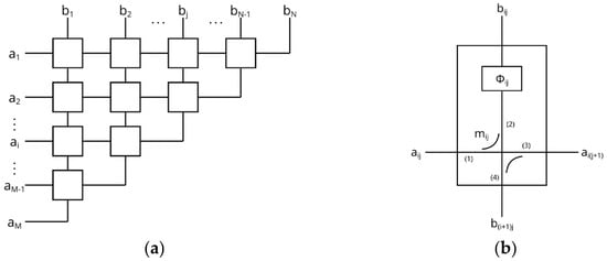
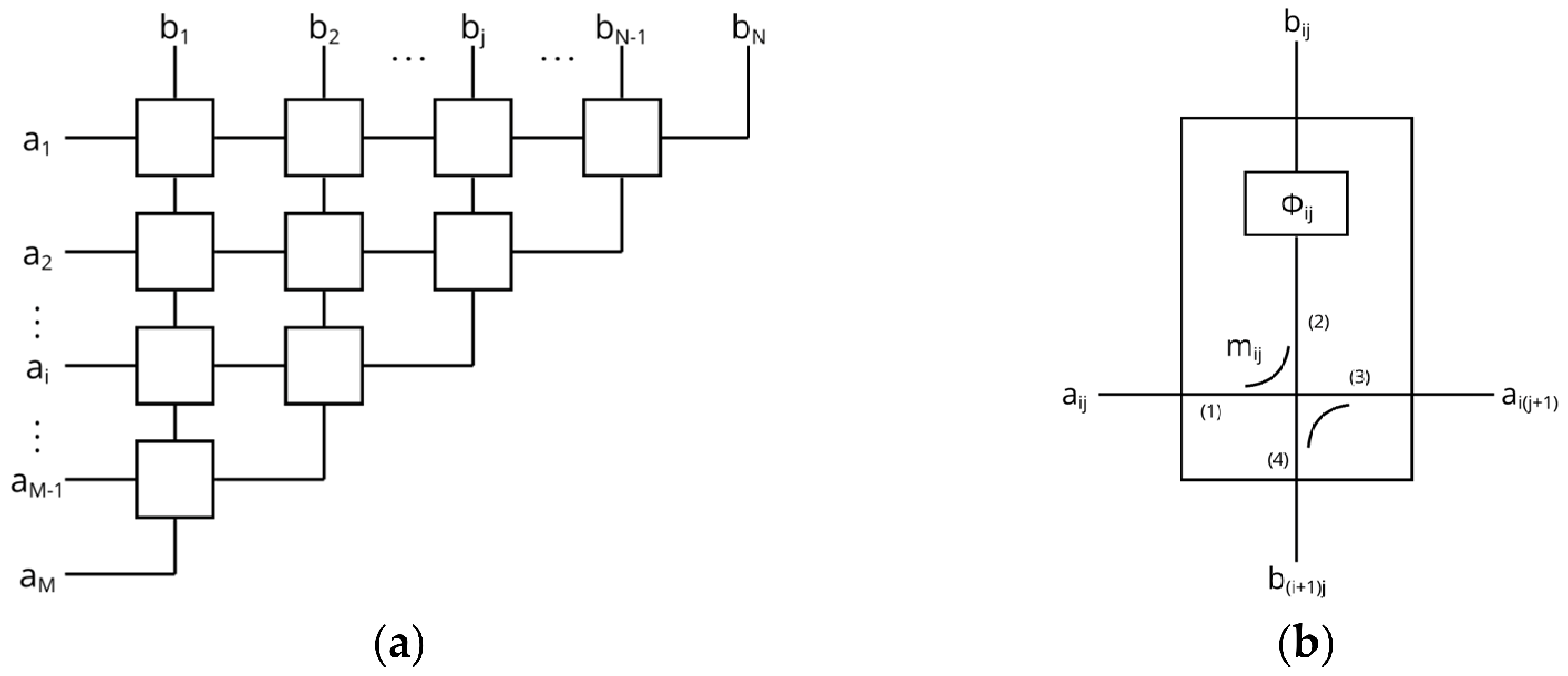
The Nolen matrix is a passive beamforming network composed of directional couplers and phase shifters arranged in a series-fed topology. It is defined by M input ports and N output ports, with M ≤ N. Each input port generates a different amplitude and phase distribution at the output ports and, consequently, a different radiation beam when the network feeds an antenna array. Under ideal lossless conditions, the output weight vectors associated with the different input ports are mutually orthogonal [2,4]. In comparison with the Blass matrix, the Nolen matrix removes the matched terminations that dissipate part of the input power while offering greater flexibility in the number of ports than the conventional Butler matrix [2,5]. Figure 1 shows a general schematic of an M × N Nolen matrix, where ai and bj denote the input and output ports, respectively and shows an elementary cell characterized by the coupling coefficient mij and phase shift ϕij.
Figure 1.
General schematic of an M × N Nolen matrix: (a) complete network, where ai and bj denote the input and output ports, respectively; (b) elementary cell characterized by the coupling coefficient mij and phase shift ϕij.
For this work, a 5 × 7 configuration was selected, providing five input ports and seven output ports. Each input is associated with one of the five synthesized beams, whereas the seven output ports provide the excitation coefficients required by the antenna array. The network is implemented using directional couplers with coupling coefficients mi,j and transmission-line phase shifters with phase values ϕi,j. These parameters were calculated from the selected orthogonal output weight vectors using the synthesis procedure proposed by Mosca et al. [5]. The resulting coupling coefficients and phase shifts are summarized in Table 1 and Table 2, respectively.
Table 1.
Coupling coefficients mi,j of the 5 × 7 Nolen matrix.
Table 2.
Phase shifts ϕi,j in degrees of the 5 × 7 Nolen matrix.
As can be observed in Table 1 and Table 2, the required coupling values vary significantly throughout the network, since each coupler extracts a different fraction of the remaining power along the series-fed paths. The coupling coefficients range from 0.378 to 0.878, corresponding to coupling levels between approximately −8.45 dB and −1.13 dB. The phase shifts are selected to provide the progressive output phase distributions associated with the five input ports while preserving the orthogonality of the corresponding excitation vectors.
2.2. Phase-Slope Equalization
In a transmission-line beamforming network, the phase shift introduced by each path varies with frequency. Therefore, when the electrical lengths between a given input port and the seven outputs are significantly different, the corresponding transmission coefficients exhibit different phase slopes. Although the required phase distribution may be obtained at the design frequency, these unequal slopes cause the relative output phases to change as the frequency moves away from 26 GHz. Consequently, the radiation beam is progressively displaced from its intended direction, producing the frequency-dependent effect known as beam squint. This behavior has also been observed in other 5 × 7 Nolen implementations, where the beams shift at frequencies above and below the design frequency [4].
To reduce this effect, the Nolen matrix was arranged in a rectangular configuration and additional transmission-line sections with electrical lengths equal to integer multiples of 360° were introduced at the output paths. Since these sections add no net phase variation at 26 GHz, they preserve the phase distribution required at the center frequency while modifying the electrical lengths and, consequently, the phase slopes of the different paths. The number of additional 360° sections was selected by comparing several configurations and evaluating the resulting beam-pointing variation over frequency. The adopted configuration produced the lowest maximum and average deviation from the pointing direction obtained at 26 GHz.
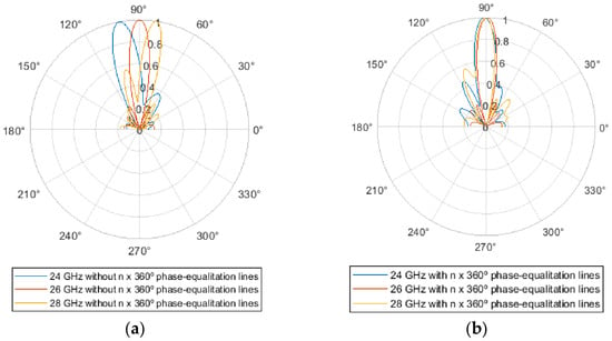
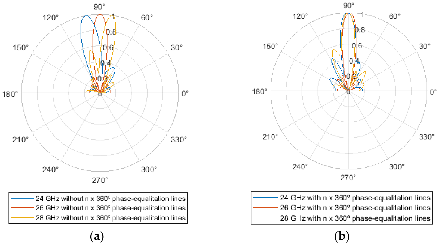
As shown in Figure 2, the unequal electrical paths produce a considerable variation in the beam direction when the operating frequency changes. After introducing the equalization sections, the phase slopes of the seven transmission coefficients become more similar, significantly reducing the angular deviation over the analyzed frequency range. The n × 360° sections therefore improve the frequency stability of the generated beams without altering their nominal pointing direction at 26 GHz.
Figure 2.
Effect of phase-slope equalization on the radiation pattern: (a) frequency-dependent beam pointing without equalization; (b) stabilized beam pointing after introducing the n × 360° transmission-line sections.
2.3. Ideal Network Validation
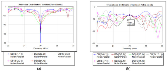
The synthesized 5 × 7 Nolen matrix was first implemented using ideal directional couplers and transmission-line phase shifters. This circuit-level model was used to verify the input matching, power distribution, relative output phases, and beam directions before the physical implementation of the network. Figure 3 shows the simulated S− parameters of the ideal 5 × 7 Nolen matrix (the reflection coefficients at the five input ports and transmission coefficients from a representative input port to the seven output ports).
Figure 3.
Simulated S− parameters of the ideal 5 × 7 Nolen matrix: (a) reflection coefficients at the five input ports; (b) transmission coefficients from a representative input port to the seven output ports.
Since the input power is ideally distributed uniformly among the seven output ports, the theoretical transmission level at each output is approximately −8.45 dB. The simulated reflection coefficients remain below −20 dB around the design frequency for all five input ports. The transmission coefficients are also close to the theoretical value and exhibit a relatively uniform response among the seven outputs. Although the matching bandwidth varies slightly depending on the excited input, the network provides satisfactory performance within the common operating band from approximately 25.5 to 26.5 GHz.
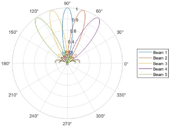
The phase progression generated at the outputs produces five different beam directions depending on the excited input port. After applying the phase-slope equalization, the network exhibits a stable beam-pointing behavior around the design frequency. Figure 4 shows the five beams generated by the ideal Nolen matrix, confirming the correct multibeam operation of the synthesized network.
Figure 4.
Normalized radiation patterns of the five beams generated by the ideal 5 × 7 Nolen matrix.
3. Microstrip and Electromagnetic Implementation
3.1. Substrate Selection
The implementation of the Nolen matrix in microstrip technology requires the realization of a wide range of characteristic impedances in the Branch-line couplers. High-impedance transmission lines require very narrow conductors, which may become too thin to be manufactured reliably using conventional microstrip fabrication processes. Conversely, low-impedance lines require larger widths, which can promote the appearance of transverse resonances and degrade the electromagnetic performance of the couplers.
Therefore, the substrate was selected by considering both the electrical losses at 26 GHz and the manufacturability of the required transmission-line widths. Rogers RO3003 was chosen, with a relative permittivity of εr = 3, a loss tangent of approximately 10−3, a dielectric thickness of 0.13 mm, and a copper thickness of 0.018 mm. With this configuration, the minimum width required by the highest-impedance coupler line is approximately 80 µm, which was established as the minimum manufacturable line width. In addition, the maximum line width associated with the lowest characteristic impedance remains below 0.2λ, corresponding to approximately 1.3 mm at 26 GHz, thereby reducing the risk of transverse resonances. A 50 Ω microstrip line has a width of approximately 0.31 mm on the selected substrate.
3.2. Branch-Line Coupler Design
The directional couplers were implemented using a Branch-line topology formed by four quarter-wavelength microstrip sections. The characteristic impedances of the two pairs of branches were determined from the coupling coefficients obtained in the theoretical synthesis. Since the required coupling level varies throughout the matrix, each coupler was designed independently.
The dimensions obtained from the initial transmission-line calculations were used as a starting point for full-wave electromagnetic optimization in AWR AXIEM. The widths and lengths of the branches were adjusted to reproduce the required coupling level at 26 GHz while maintaining the input reflection and isolation coefficients below −20 dB within the 25.5–26.5 GHz operating band. The output phases were also corrected to provide approximately 90° for S21 and 180° for S31 at the design frequency, in accordance with the phase convention adopted in the ideal network.
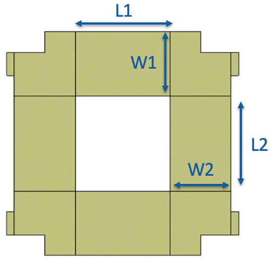
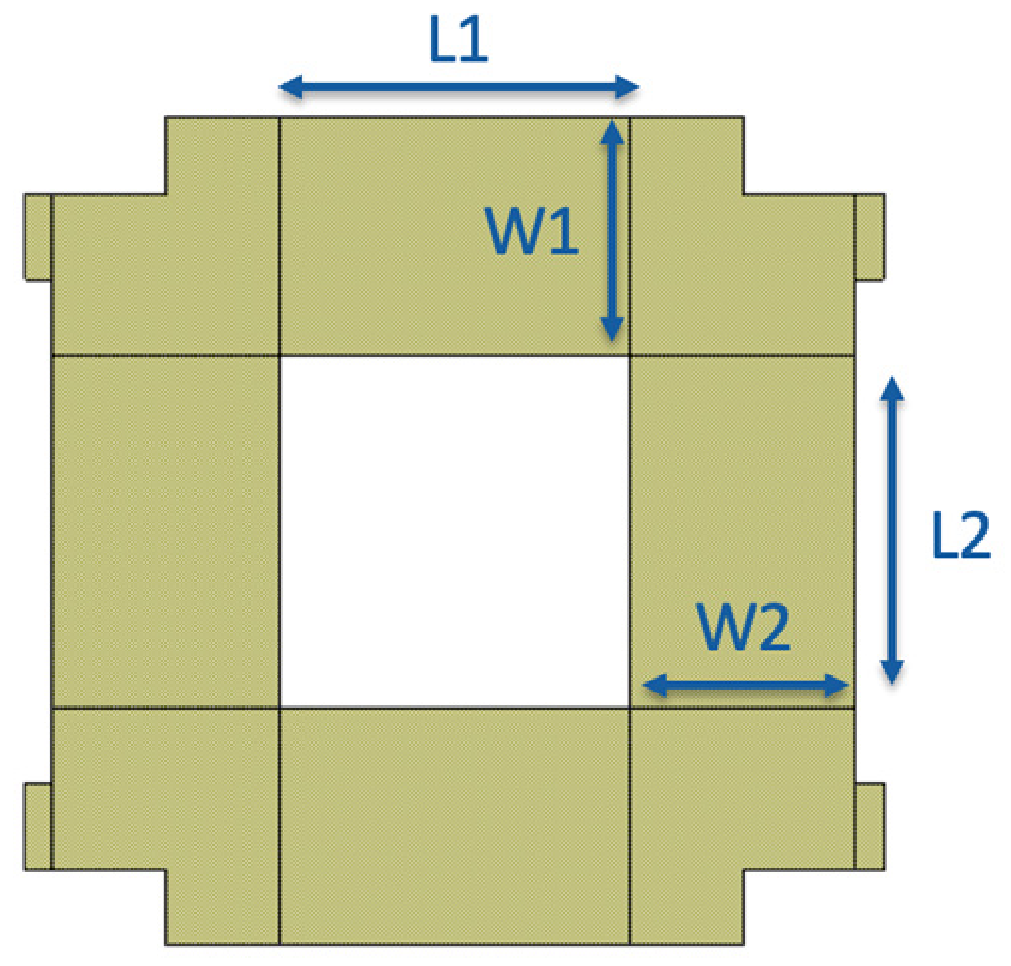
The couplers used in the final matrix therefore correspond to the structures obtained after electromagnetic optimization rather than to the preliminary circuit-level designs. The geometrical parameters used to define the microstrip Branch-line couplers are illustrated in Figure 5, where L1 and L2 denote the branch lengths and W1 and W2 their corresponding widths. The optimized physical dimensions of the different couplers are summarized in Table 3.
Figure 5.
Geometrical parameters of the microstrip Branch-line coupler, showing the branch lengths L1 and L2 and the corresponding widths W1 and W2.
Table 3.
Optimized widths and lengths of the Branch-line couplers used in the 5 × 7 Nolen matrix.
The most critical cases in the proposed design are Coupler 11 and Coupler 34, since they correspond to the extreme characteristic impedance values required by the network. Coupler 11 presents the lowest impedance, whereas Coupler 34 presents the highest one. High-impedance microstrip lines require very narrow widths, which may become difficult to fabricate, while low-impedance lines require wider traces and may increase the risk of transverse resonances, potentially degrading the circuit performance. These constraints were therefore taken into account during the substrate selection and physical implementation of the couplers.
3.3. Layout Generation
Once the electromagnetically optimized couplers had been obtained, they were assembled according to the rectangular topology of the 5 × 7 Nolen matrix. The ideal components were replaced by their corresponding microstrip layouts, and the interconnecting transmission lines were designed to provide the phase shifts determined during the theoretical synthesis. Due to the large electrical lengths required in some paths, several lines were implemented using meandered geometries in order to reduce the overall dimensions of the network.
The bends introduced in the meandered sections produce an additional phase contribution that cannot be represented by a single fixed correction. This contribution depends on the total length and geometry of each line, as well as on the coupler to which it is connected. Therefore, the phase of each interconnecting line containing bends was adjusted individually to preserve the phase distribution required at the output ports. This procedure ensured that the physical routing did not significantly modify the phase relationships obtained in the ideal network.
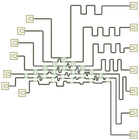
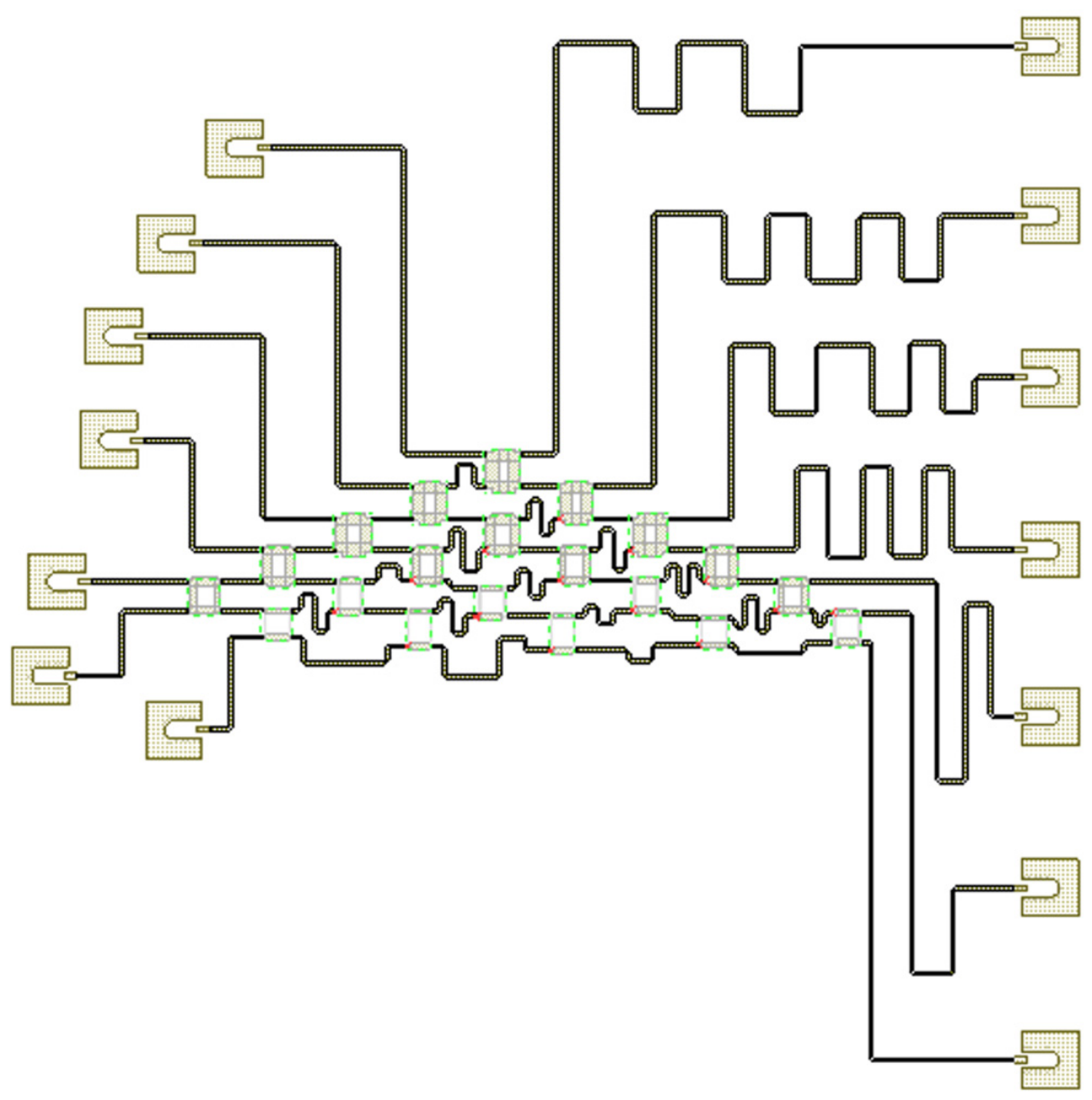
For the experimental connection of the network, Rosenberger 18S142-40ML5 connectors (Rosenberger Hochfrequenztechnik GmbH & Co. KG, Fridolfing, Germany) were selected. The transition between the connector and the microstrip line was electromagnetically analyzed, and a short matching section was introduced to improve the transition to the 50 Ω lines of the matrix. The output connectors were arranged with sufficient separation to facilitate assembly and measurement. After incorporating the connector transitions and completing the individual phase adjustment of the meandered lines, the final layout of the 5 × 7 Nolen matrix was obtained, as shown in Figure 6.
Figure 6.
Final layout of the 5 × 7 microstrip Nolen matrix including the input and output connectors.
4. Results
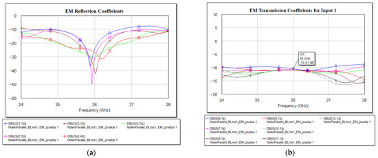
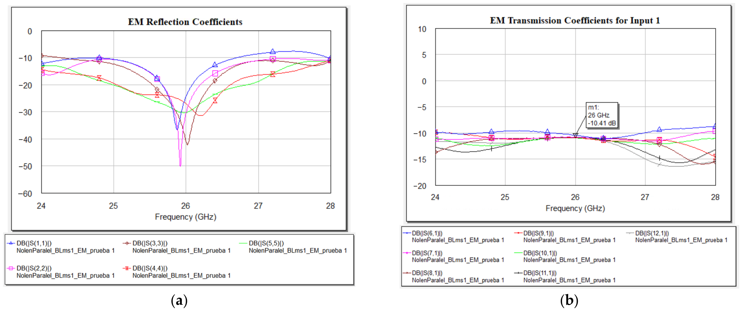
The electromagnetic simulation of the complete Nolen matrix shows satisfactory matching around the design frequency. The reflection coefficients of the five input ports remain below approximately −15 dB within the 25.5–26.5 GHz operating band, as shown in Figure 7a.
Figure 7.
Electromagnetically simulated S− parameters of the complete 5 × 7 Nolen matrix. (a) Reflection coefficients at the five input ports. (b) Transmission coefficients from a representative input port to the seven output ports.
The transmission coefficients from each input to the seven output ports remain reasonably uniform throughout the same frequency range, as shown in Figure 7b. Although additional conductor, dielectric, and radiation losses reduce the transmission levels by approximately 2 dB with respect to the ideal value, the power distribution among the outputs remains sufficiently balanced for multibeam operation. Moreover, the maximum variation among the transmission coefficients over this frequency range is approximately 1 dB, indicating a similar transmission response for all output paths.
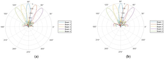
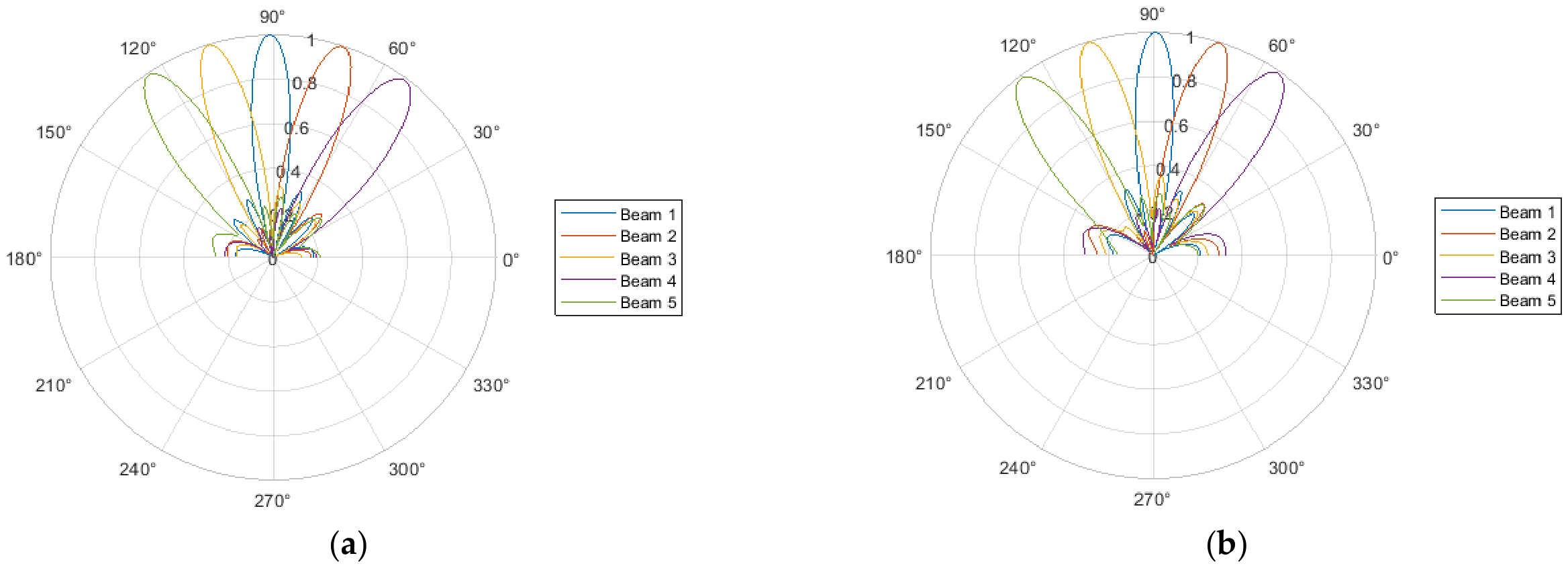
The output amplitude and phase distributions generate five different beams according to the excited input port. The simulated array factors confirm the correct beamforming behavior of the network and show limited variation in the pointing directions between 25.5 and 26.5 GHz, demonstrating the effectiveness of the phase-slope equalization (Figure 8).
Figure 8.
Normalized radiation patterns of the five beams generated by the electromagnetically simulated 5 × 7 Nolen matrix. (a) Radiation patterns at 25.5 GHz. (b) Radiation patterns at 26.5 GHz.
5. Conclusions
A 5 × 7 Nolen beamforming network has been designed in microstrip technology for operation at 26 GHz. The proposed rectangular configuration and phase-slope equalization reduce beam-pointing variation over frequency; the maximum beam-pointing variation remains below 3° over the 25.5–26.5 GHz frequency range. Full-wave electromagnetic simulations confirm adequate matching, balanced output transmission, and the generation of five distinct beams within the 25.5–26.5 GHz operating band. The final layout, including connector transitions, is suitable for fabrication and subsequent experimental validation. The proposed 5 × 7 microstrip Nolen matrix presents a compact overall footprint of approximately 83 mm × 83 mm, which makes the design suitable for integration in millimeter-wave multibeam antenna systems. In addition, the estimated fabrication cost of the bare PCB is in the range of €200–300 for a small prototype batch, considering the use of Rogers RO3003 substrate with a thickness of 0.13 mm and 18 μm copper metallization. This cost may vary depending on the manufacturer, fabrication tolerances, and production volume, but it remains compatible with low-volume prototyping and experimental validation at 26 GHz.
Author Contributions
Conceptualization, M.C. and M.B.; methodology, M.C. and M.B.; software, M.C.; validation, M.C. and M.B.; formal analysis, M.C. and M.B.; investigation, M.C.; resources, M.B.; data curation, M.C.; writing—original draft preparation, M.C.; writing—review and editing, M.C. and M.B.; visualization, M.C.; supervision, M.B.; project administration, M.B. All authors have read and agreed to the published version of the manuscript.
Funding
This research received no external funding.
Institutional Review Board Statement
Not applicable.
Informed Consent Statement
Not applicable.
Data Availability Statement
The data presented in this study are available from the corresponding author upon reasonable request.
Conflicts of Interest
The authors declare no conflicts of interest.
References
- Hong, W.; Jiang, Z.H.; Yu, C.; Zhou, J.; Chen, P.; Yu, Z.; Zhang, H.; Yang, B.; Pang, X.; Jiang, M.; et al. Multibeam Antenna Technologies for 5G Wireless Communications. IEEE Trans. Antennas Propag. 2017, 65, 6231–6249. [Google Scholar] [CrossRef] [Scilit]
- Guo, Y.J.; Ansari, M.; Fonseca, N.J.G. Circuit Type Multiple Beamforming Networks for Antenna Arrays in 5G and 6G Terrestrial and Non-Terrestrial Networks. IEEE J. Microw. 2021, 1, 704–722. [Google Scholar] [CrossRef] [Scilit]
- Fonseca, N.J.G. Printed S-Band 4 × 4 Nolen Matrix for Multiple Beam Antenna Applications. IEEE Trans. Antennas Propag. 2009, 57, 1673–1678. [Google Scholar] [CrossRef] [Scilit]
- Fuentes-Pascual, M.A.; Ferrando-Rocher, M.; Herranz-Herruzo, J.I.; Baquero-Escudero, M. Five-Beam Fully Metallic Nolen Matrix-Based Array Antenna for 5G Applications at 26 GHz. IEEE Trans. Antennas Propag. 2024, 72, 8852–8857. [Google Scholar] [CrossRef] [Scilit]
- Mosca, S.; Bilotti, F.; Toscano, A.; Vegni, L. A Novel Design Method for Blass Matrix Beam-Forming Networks. IEEE Trans. Antennas Propag. 2002, 50, 225–232. [Google Scholar] [CrossRef] [Scilit]

Disclaimer/Publisher’s Note: The statements, opinions and data contained in all publications are solely those of the individual author(s) and contributor(s) and not of MDPI and/or the editor(s). MDPI and/or the editor(s) disclaim responsibility for any injury to people or property resulting from any ideas, methods, instructions or products referred to in the content. |
© 2026 by the authors. Licensee MDPI, Basel, Switzerland. This article is an open access article distributed under the terms and conditions of the Creative Commons Attribution (CC BY) license.