


Abstract
Friction stir welding (FSW) of steels imposes severe thermo-mechanical loading on the welding tool, making tool material and structural integrity critical to process feasibility. This study investigates a sequential, failure-driven tool-development approach for butt welding 3 mm S355JR structural-steel sheets. Two tool concepts were evaluated. The first consisted of an alumina-based ceramic shoulder combined with a carbide pin. The ceramic shoulder fractured in all four repeated preliminary trials when traverse motion was initiated, demonstrating the limitation of the investigated hybrid architecture under the applied loading conditions. Based on this failure, the tool was redesigned as a monolithic WC–Co cemented carbide construction with a reduced shoulder diameter. The redesigned tool completed the investigated 16-condition experimental matrix without macroscopic fracture. Visual inspection, transverse tensile testing, and metallographic examination showed that continuous evaluable joints were obtained at 1400 rev/min with a 1° tool tilt. Metallography revealed internal tunnel- or flow-related discontinuities in several conditions despite base-material fracture during tensile testing. The best-performing investigated condition was 1400 rev/min, 85 mm/min and 1° tilt, for which no characteristic internal defect was detected in the examined cross-section. Because this condition occurred at the boundary of the investigated parameter range, it should not be interpreted as a global optimum.
1. Introduction
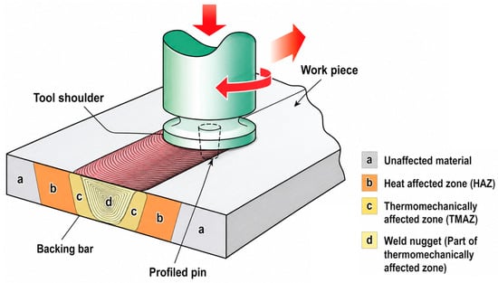
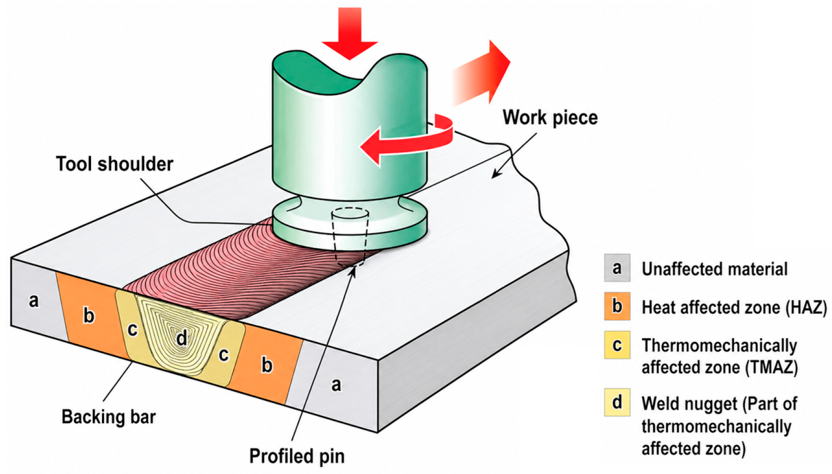
Friction stir welding (FSW) is a solid-state joining process developed at The Welding Institute (TWI) in 1991. In FSW, a rotating, non-consumable tool generates heat through friction and plastic deformation while transporting and consolidating material across the joint line [1]. Although the process was initially developed for aluminum alloys, its application to steels was investigated at an early stage. Thomas et al. [2] demonstrated the feasibility of FSW in low-carbon and 12% Cr steels and identified the development of suitable tool materials as a prerequisite for broader application. Subsequently, Lienert et al. [3] produced defect-free welds in 6.3 mm AISI 1018 mild steel using molybdenum- and tungsten-based tools, while reporting substantial axial forces, torque, and process temperatures. These early investigations established the feasibility of steel FSW but also demonstrated that the thermal and mechanical demands imposed on the tool are considerably more severe than those encountered during FSW of lower-softening-temperature alloys [2,3,4]. The process principle, heat-generation mechanisms, and material-flow behavior of FSW have been discussed extensively in the literature [4,5]. A schematic representation of the process and the associated weld zones is shown in Figure 1 [6].
Figure 1.
Schematic illustration of the FSW process and the characteristic weld zones [6].
In steel FSW, tool performance depends on the combined effects of high-temperature strength, hardness, fracture toughness, thermal stability, chemical compatibility and wear resistance. These properties must be maintained under substantial axial, torsional, and transverse loads, as well as under steep thermal gradients generated during plunging, dwelling, and traversing. Accordingly, tool material, tool geometry, load-bearing capacity and degradation mechanisms are strongly interdependent and influence both weld quality and process economy [7]. Reviews of steel FSW have shown that progress in the field has been closely associated with the development of more reliable tools and with improved control of material flow and process temperature [8]. Tool cost, wear behavior, geometry and service life remain important barriers to industrial implementation [9]. In addition, tool damage and inadequate heat generation limit the application of FSW to hard materials [10], while rapid tool degradation and high tooling costs continue to restrict commercial adoption [11]. Consequently, the suitability of a tool material cannot be assessed solely from its nominal hardness or maximum service temperature; its response under the coupled thermo-mechanical loading of the actual process must also be considered.
Refractory-metal and superabrasive systems have therefore received considerable attention. Polycrystalline cubic boron nitride (PCBN), often integrated with W–Re-based structural components, is among the established tooling solutions for steel FSW because of its high hardness and thermal stability. Nevertheless, PCBN-based tools remain susceptible to degradation. Giorjão et al. [12] quantified the volumetric wear of a PCBN/W–Re composite tool during friction stir processing of X70 pipeline steel. Profilometry and optical microscopy revealed progressive volume loss with increasing numbers of plunges and processing distance, while boron-, nitrogen-, and tungsten-containing species originating from the tool were detected in the processed steel. These findings demonstrate that tool degradation may influence not only tool life and dimensional stability but also the composition of the processed material.
Tungsten-based alloys have also been investigated because of their high-temperature strength and resistance to mechanical damage. Gan et al. [13] developed a thermo-mechanical framework for screening tool materials for FSW of L80 steel and reported substantial differences between commercially pure tungsten and W–Re tools in their resistance to deformation. Ragu Nathan et al. [14] experimentally evaluated tungsten-based tools containing approximately 90, 95, and 99% W during FSW of high-strength low-alloy steel. Their post-weld analyses revealed differences in microstructural stability, with the 99% W material containing 1% La2O3 exhibiting the highest stability among the investigated materials. These results indicate that tool performance may vary substantially within a single material family because of differences in composition and high-temperature microstructural stability.
WC-based cemented carbides provide another promising tooling class. Their high hardness and thermal stability are attractive for steel FSW; however, their resistance to transient mechanical loading depends strongly on composition, microstructure, tool geometry, and load transfer. Brittle fracture therefore remains an important design consideration for ceramic tool architectures subjected to asymmetric loading. Tiwari et al. [15] compared WC–6 wt% Co and WC–10 wt% Co tools during FSW of DH36 steel and identified distinct degradation mechanisms for the two grades. The WC–6Co tool exhibited intergranular degradation associated with separation of WC grains and subsequent crack propagation, whereas adhesion, abrasion, oxidation, diffusion, and crack initiation contributed to the degradation of the WC–10Co tool. Progressive wear was strongly influenced by the thermal conditions of the process, and minimum wear was observed at lower rotational speed and higher traverse speed. These findings directly demonstrate the interaction between cemented-carbide composition, process parameters, and tool degradation.
The importance of this process–tool interaction was also demonstrated for WC–Ni tools during FSW of 3 mm high-carbon steel [16]. Higher traverse speed combined with lower rotational speed reduced tool degradation, whereas higher rotational speed and lower traverse speed increased the temperature and promoted adhesive wear and oxidation. Under the least severe condition investigated, a single WC–Ni tool was used over a welding distance of up to 1000 mm without significant damage. More recently, Bhatia et al. [17] examined the effect of tool geometry during FSW of 3 mm AISI 1018 carbon steel using a tungsten-carbide tool containing 7 wt% Co. Their results confirmed that successful carbide-tool application depends not only on the material itself but also on pin geometry and the resulting material-flow conditions. This consideration is particularly important for thin-sheet steel FSW, in which relatively small changes in tool geometry or process parameters can modify tool loading, heat generation, and material containment.
Ceramic and cermet tools offer a different approach to high-temperature tooling. Their high hardness and thermal resistance are attractive for steel FSW, although their relatively low fracture tolerance makes them sensitive to tool geometry, load transfer, and transient operating conditions. Nevertheless, recent studies indicate that ceramic-based tooling should not be regarded as intrinsically unsuitable for steel FSW. Mori et al. [18] successfully welded 15 mm low-carbon steel plate using a silicon-nitride tool and showed that rotational speed and tool tilt affected groove formation and weld integrity. In particular, reducing the tilt angle contributed to the formation of a defect-free joint, demonstrating the coupling between ceramic-tool loading, heat generation, and material flow.
The potential of non-metallic tooling is further illustrated by recent cermet and silicon-nitride developments. Murakami et al. [19] used TiC0.5N0.5–W cermet tools for friction stir spot welding of 1 mm SPCC low-carbon steel. The optimized tool containing 72 wt% W completed more than 2000 welding cycles while maintaining sound joints. Mori et al. [20] subsequently investigated a hemispherical silicon-nitride tool for tilted-tool FSW of steel. Tool life was strongly dependent on rotational speed: at the reported optimum of 500 rev/min, neither significant wear nor fracture was observed over a welding distance of 10 m, whereas both lower and higher rotational speeds produced substantially shorter tool life. These results demonstrate that ceramic and cermet tools can be viable for steel processing when tool material, geometry, and loading conditions are appropriately matched.
Overall, the literature indicates that steel-FSW tool performance is governed by the interaction of intrinsic material properties, tool architecture, geometry and process conditions. PCBN/W–Re systems, tungsten alloys, WC-based cemented carbides, silicon nitride and cermets have all shown technical potential, but each system is associated with characteristic limitations involving wear, deformation, oxidation, chemical interaction or brittle fracture. Moreover, the behavior of one tool architecture cannot be transferred directly to another. In particular, the successful use of monolithic or hemispherical silicon-nitride tools does not establish the suitability of an alumina-based shoulder used as one component of a mechanically heterogeneous shoulder–pin assembly.
To the author’s knowledge, within the literature reviewed for the present study, no directly comparable investigation has been reported in which an alumina-based ceramic shoulder combined with a separate carbide pin was first subjected to repeated survivability trials during FSW of thin structural steel, followed by an explicit redesign of the failed concept into a monolithic carbide tool. This distinction is important because a failure-driven development route enables tool-material behavior and architectural limitations to be assessed sequentially, rather than treating different tool materials as interchangeable alternatives.
The present study investigates such a failure-driven tool-development route for FSW of 3 mm S355JR structural steel. In the first stage, a hybrid tool comprising an alumina-based ceramic shoulder and a carbide pin was subjected to repeated preliminary welding trials. After repeated fracture of the ceramic shoulder during the transition from dwell to traverse, the design was replaced by a monolithic WC–Co cemented-carbide tool with a reduced shoulder diameter. In the second stage, the redesigned tool was evaluated over a defined matrix of rotational speed, traverse speed and tool tilt. The resulting joints were assessed by visual inspection, transverse tensile testing and metallographic examination.
The contribution of this study is therefore not to claim a general superiority of cemented carbide over ceramic tooling. Instead, it identifies the failure limitation of the investigated hybrid alumina–carbide architecture and documents the subsequent transition to a monolithic carbide tool capable of producing evaluable joints in thin S355JR steel. The study further examines how tool tilt and the combination of rotational and traverse speeds interact with the redesigned tool to determine weld formation and internal integrity.
2. Materials and Methods
2.1. Experimental Strategy and Tool-Development Logic
The experimental program followed a sequential, failure-driven tool-development strategy rather than a direct comparison of two equivalent tool materials. Stage I was designed as a tool-survivability screening experiment using the hybrid ceramic-shoulder/carbide-pin concept (Concept A). Four repeated trials were performed at the same baseline condition of 1000 rev/min and 35 mm/min. The purpose of this stage was to determine whether the proposed tool architecture could survive plunge, dwell, and the transition to traverse motion.
Following repeated failure of the ceramic shoulder, Concept A was discontinued, and the tool was redesigned. Stage II therefore evaluated Concept B, a monolithic WC–Co cemented-carbide tool, using a 2 × 4 × 2 matrix consisting of two rotational speeds (1000 and 1400 rev/min), four traverse speeds (35, 55, 65 and 85 mm/min) and two tool-tilt conditions (0° and 1°). The objective of Stage II was first to identify conditions capable of producing a continuous weld and then to evaluate the resulting joints by visual inspection, transverse tensile testing and metallography.
Table 1 summarizes the sequential experimental program and clarifies the different objectives of the two stages.
Table 1.
Sequential experimental program and tool-development stages.
2.2. Base Material, Machine and Fixture
The workpieces used in this study were 3 mm thick hot-rolled S355JR structural-steel sheets. S355JR was selected because it is a widely used structural grade and is less demanding than many high-strength steels, making it appropriate for a feasibility-level tool-material screening study. The nominal material data in Table 2 are stated according to EN 10025-2.
Table 2.
Nominal chemical composition and mechanical properties of S355JR structural steel according to EN 10025-2 [21].
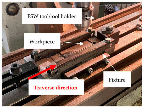
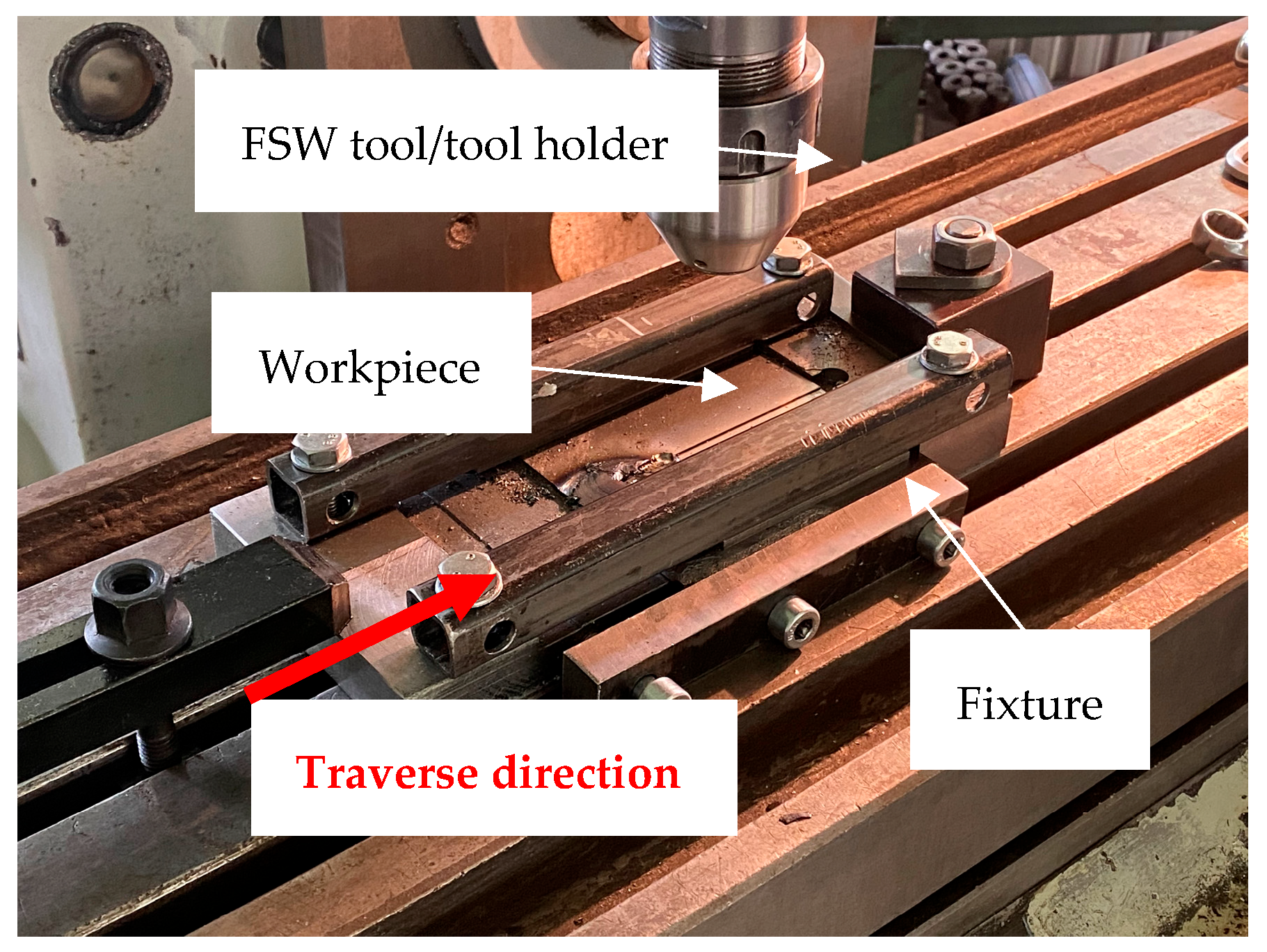
Experiments were performed on a converted STANKOIMPORT SSSR 252 universal milling machine, and the sheets were clamped in a dedicated fixture, as shown in Figure 2. The main selection criteria were the rigidity of the machine frame and spindle. This point is not a minor experimental detail: in steel FSW, fixture stiffness and heat extraction influence axial force, shoulder contact, and material-flow stability [4,5,7].
Figure 2.
Experimental fixture on the machine table.
2.3. Tool-Material Concepts
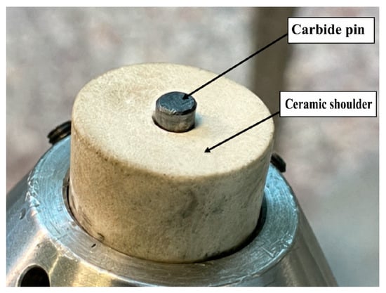
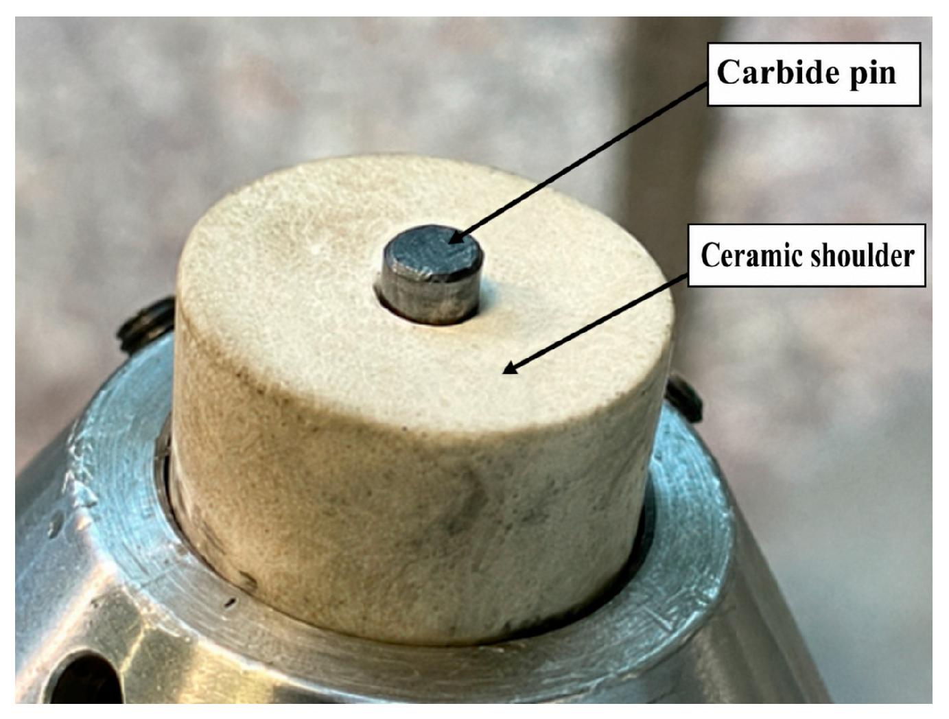
Concept A was a hybrid tool consisting of an alumina-based ceramic shoulder and a tungsten-carbide-based pin (Figure 3).
Figure 3.
Concept A: ceramic tool.
The ceramic shoulder diameter was 20 mm. The ceramic component was selected because of its high hardness and high-temperature capability, whereas the carbide pin was intended to provide the local strength required for penetration and material stirring. The concept was specifically evaluated to determine whether the ceramic shoulder could withstand the combined thermal and mechanical loading generated during FSW of S355JR steel. Table 3 reports the material data used for the tool-material selection step.
Table 3.
Reported properties of the alumina-based ceramic shoulder used in Concept A.
Following the repeated failure of Concept A, the tool was redesigned as Concept B, a monolithic WC–Co cemented-carbide tool. The redesign involved two simultaneous changes: elimination of the mechanical interface between the pin and shoulder, and reduction of the shoulder diameter from 20 mm to 16 mm. The latter modification was introduced to reduce the moment generated by asymmetric shoulder loading during traverse.
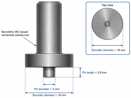
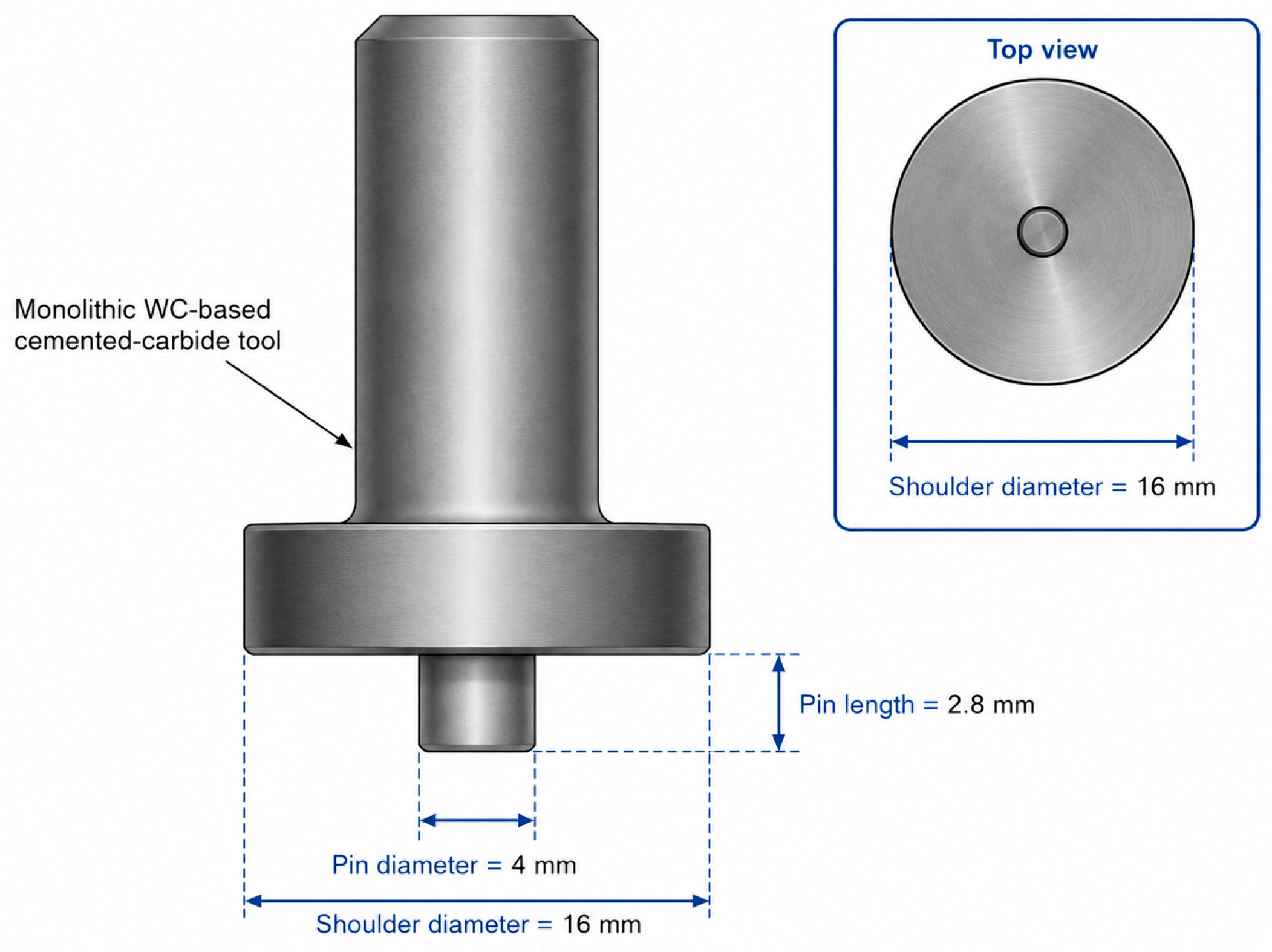
Concept B was manufactured from a P30-type cemented carbide specified as 88 wt% WC and 12 wt% Co. The tool was manufactured as a monolithic component by electrical discharge machining (EDM). The cylindrical pin had a diameter of 4 mm and a length of 2.8 mm, while the shoulder diameter was 16 mm. The 2.8 mm pin length was selected for the 3 mm sheet thickness in order to obtain near-full-thickness stirring while avoiding intentional contact between the pin tip and the backing plate. The geometry and principal dimensions are shown in Figure 4. Material properties used for the tool-material selection are summarized in Table 4.
Figure 4.
Concept B: monolithic tungsten-carbide.
Table 4.
Reported properties of the P30-type cemented-carbide tool material used for Concept B.
2.4. Experimental Design and Welding Sequence
Stage I consisted of four repeated trials with Concept A at a fixed rotational speed of 1000 rev/min and a traverse speed of 35 mm/min. These trials were not intended as a parameter-optimization matrix; their purpose was solely to assess whether the hybrid tool could survive the transition from plunge and dwell to stable traverse welding. In all four trials, the ceramic shoulder fractured immediately after traverse motion was initiated. Consequently, no continuous welded specimen suitable for mechanical or metallographic evaluation was produced with Concept A, and further parameter variation with this tool was discontinued.
Stage II was therefore performed with the redesigned monolithic WC–Co tool. The complete Stage II parameter matrix is given in Table 5. Rotational speeds of 1000 and 1400 rev/min and traverse speeds of 35, 55, 65 and 85 mm/min were combined with tool tilts of 0° and 1°, resulting in 16 experimental conditions. The ceramic trials are not included in Table 5 because Table 5 represents only the parameter matrix used after the transition to Concept B. The complete two-stage program is summarized separately in Table 1.
Table 5.
Stage II experimental matrix for the monolithic WC–Co cemented-carbide tool.
A tool tilt of 0° denotes a tool axis perpendicular to the sheet surface. For the 1° condition, the tool was inclined opposite to the traverse direction so that the trailing region of the shoulder applied a greater forging action to the plasticized material. Each Stage II experiment followed the same sequence: alignment of the tool axis with the butt joint, rotating plunge approximately 5 mm from the sheet edge, penetration until the 2.8 mm pin was fully engaged and the shoulder contacted the plate surface, a 20 s dwell period, initiation of traverse motion, termination of traverse, and tool retraction.
2.5. Sequential Weld-Quality Assessment
The experimental results were evaluated using a sequential acceptance procedure rather than a weighted numerical quality index. Tool integrity was assessed first. A condition was rejected if the tool failed during welding. For conditions completed without tool failure, the weld surface was inspected, and the condition was rejected from further mechanical evaluation if no continuous joint was produced or if a pronounced crown-side groove indicated insufficient material containment.
Conditions passing the tool-integrity and visual-inspection stages were subsequently evaluated by transverse tensile testing and metallographic cross-section examination. Tensile response and fracture location were considered together; however, base-material fracture was not interpreted as proof of internal weld integrity. Metallography was therefore used to identify tunnel-type or flow-related internal discontinuities that were not apparent from the external weld surface or the monotonic tensile-test fracture location.
Traverse speed was retained as a process-productivity parameter but was not mathematically combined with the quality observations. The ratio n/vf is reported only as a descriptive measure of tool revolutions per unit weld length and is not interpreted as absolute heat input because torque, axial force, and temperature were not measured.
3. Results
The tensile specimens were extracted transverse to the welding direction. Metallographic samples were prepared from representative cross-sections of the welded region after visual inspection.
3.1. Tool Survival and Visual Weld Quality
The first result was not a weld property but a tool-integrity result. The ceramic shoulder fractured in all four repeated trials during the start of traverse. Although the pin began to heat and plasticize the sheet, the shoulder could not survive the combined thermal, compressive, and bending loads. Therefore, Concept A was rejected for the investigated configuration.
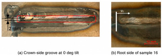
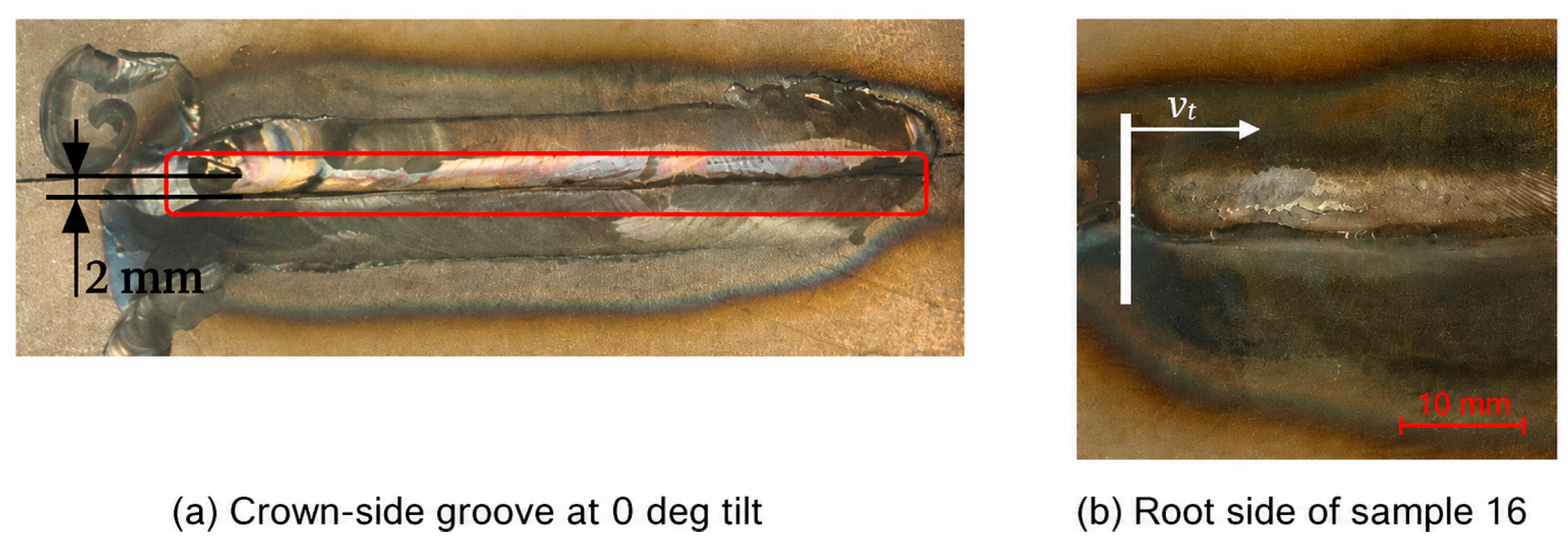
The monolithic WC–Co tool completed all 16 Stage II conditions without macroscopic tool fracture. Nevertheless, tool survival alone did not guarantee acceptable weld formation. All experiments performed at 0° tool tilt (samples 1–8) produced a pronounced crown-side groove located approximately 2 mm from the pin path. Figure 5a shows sample 5 (1400 rev/min, 35 mm/min, 0°) as a representative example of this defect. The repeated occurrence of the groove under the 0° condition indicates inadequate containment and forging of the plasticized material by the trailing shoulder region.
Figure 5.
Representative visual results obtained with the monolithic WC–Co tool: (a) sample 5 crown-side, produced at 1400 rev/min, 35 mm/min and 0° tilt, showing the characteristic crown-side groove approximately 2 mm from the pin path, (b) root-side appearance of sample 16, produced at 1400 rev/min, 85 mm/min and 1° tilt.
At 1° tilt and 1000 rev/min (samples 9–12), reliable bonding was still not achieved. Only samples 13–16, produced at 1400 rev/min and 1° tilt, formed continuous joints suitable for subsequent tensile and metallographic evaluation. Figure 5b shows the root-side appearance of sample 16. This surface observation was used only as a visual inspection result; internal integrity was evaluated separately by metallography.
3.2. Transverse Tensile Testing
Transverse tensile specimens were prepared with a width of 10 mm and tested on an Instron 4482 tensile-testing machine. One transverse tensile specimen was tested for each of samples 13–16. Consequently, no statistical dispersion or standard deviation can be reported, and the measured tensile values are treated as screening-level results rather than statistically representative material properties. The resulting maximum loads, elongations, and calculated tensile strengths are listed in Table 6.
Table 6.
Screening tensile-test results obtained from one transverse specimen for each of samples 13–16.
Samples 13–16 fractured in the base material outside the weld and outside the heat-affected zone (Figure 6). From a monotonic tensile perspective, this indicates that the weld region was not the weakest location of these specimens.
Figure 6.
Tensile-tested FSW specimens 13, 14, 15, and 16 after fracture.
This tensile result must be interpreted carefully. Base-material fracture does not prove that the weld is free from internal defects, nor does it qualify the procedure for fatigue or impact loading. It only shows that the static tensile capacity of the tested specimens was not controlled by the stirred zone under the applied loading conditions. Although sample 13 showed the highest measured tensile response among the four evaluated conditions, the tensile results alone did not distinguish internal weld quality because all four specimens fractured in the base material outside the weld and heat-affected zone. Metallographic examination was therefore required to distinguish the conditions on the basis of internal weld integrity. Consequently, the final interpretation of samples 13–16 is based on the combined evidence from fracture location and cross-sectional metallography rather than on a weighted numerical index.
3.3. Metallographic Quality Assessment
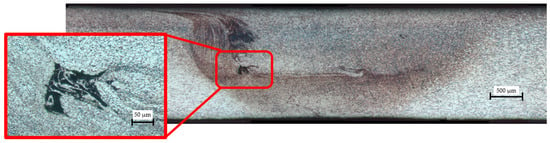
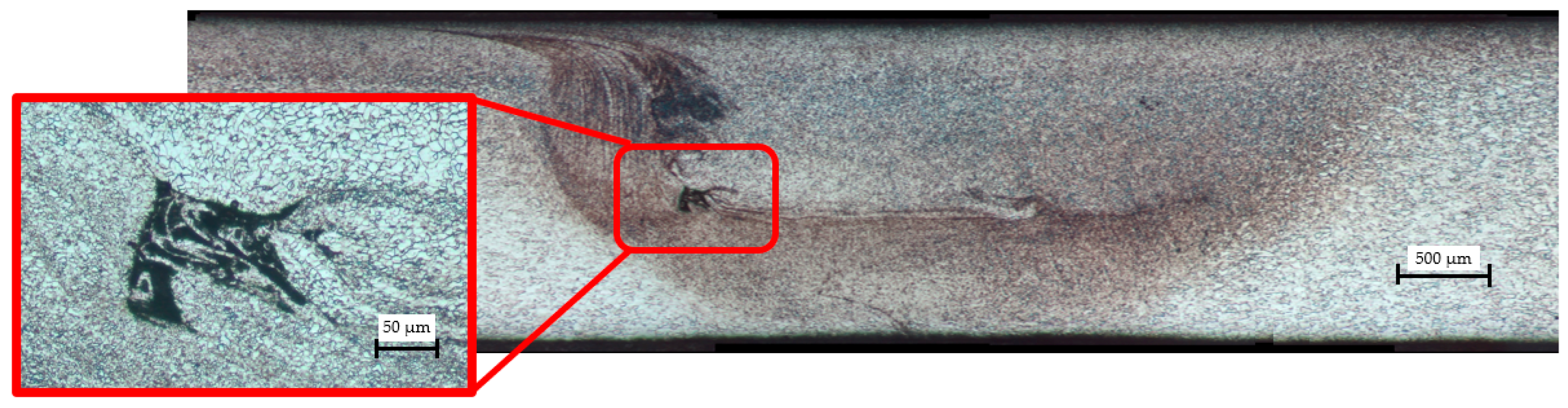
Cross-sections were ground using P600, P800, and P1000 abrasive papers, polished and etched with 2% Nital. In the micrographs, the left side corresponds to the advancing side and the right side to the retreating side as shown Figure 7.
Figure 7.
Metallographic cross-section of FSW sample 13 showing a tunnel-type defect in the weld zone.
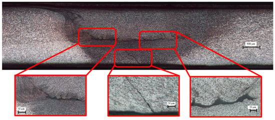
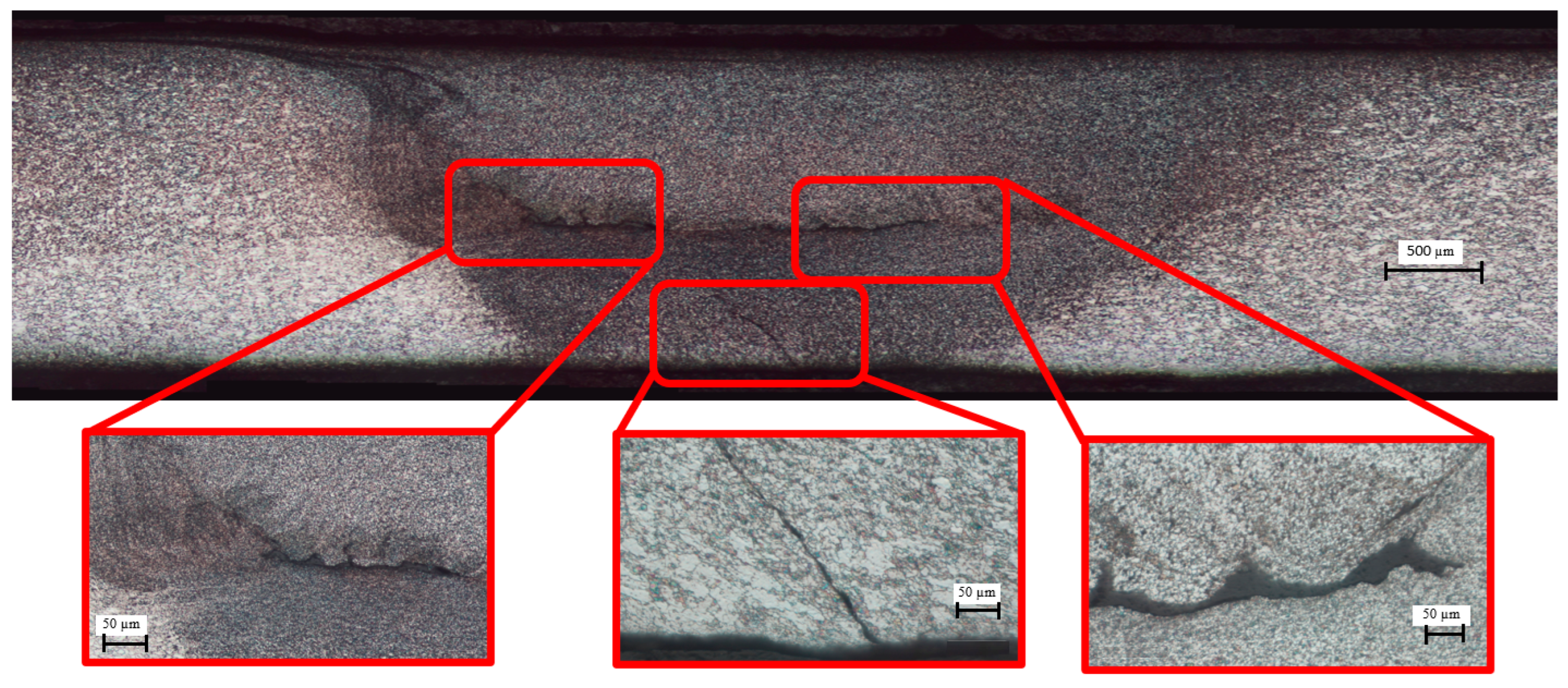
Metallography was more discriminating than tensile testing. Sample 13 contained an approximately 0.2 mm tunnel-type defect in the stirred region. Samples 14 and 15 (see Figure 8) contained flow-related discontinuities between the crown and root sides; the reported width of the discontinuity was approximately 3 mm. Such defects act as stress concentrators and may become critical under fatigue, impact, or corrosive loading even if they do not govern monotonic tensile failure.
Figure 8.
Metallographic cross-section of FSW sample 15 showing a material-flow-related defect in the weld zone.
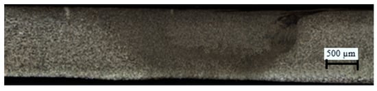
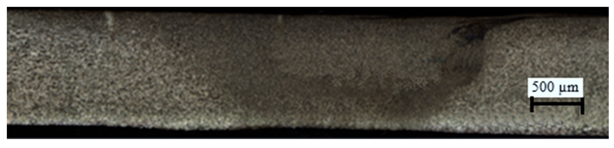
In sample 16, produced at n = 1400 rev/min, vf = 85 mm/min and α = 1°, no characteristic internal defect was detected in the examined cross-section, as shown Figure 9. A fine-grained stirred zone was observed qualitatively in the weld region of the examined samples. Within the present matrix, sample 16 is therefore the best examined condition.
Figure 9.
Metallographic cross-section of FSW sample 16, showing no characteristic internal defect in the examined weld zone.
4. Discussion
The repeated failure of Concept A demonstrates a limitation of the investigated hybrid ceramic-shoulder/carbide-pin architecture rather than a general unsuitability of ceramic materials for FSW. The alumina shoulder survived plunge and dwell but fractured in all four trials when traverse began, where asymmetric shoulder contact introduces combined bending, torsional, and thermal loading. The repeated brittle fracture is therefore consistent with insufficient damage tolerance under transient thermo-mechanical loading. Because neither fractography nor in-process force measurements were performed, the exact fracture mechanism cannot be established. Published steel-FSW studies likewise show that even very hard high-temperature tool materials remain susceptible to fracture and wear under unfavorable loading conditions [12,15,20].
The transition from Concept A to Concept B involved both a material and structural redesign: the hybrid pin–shoulder architecture was replaced by a monolithic WC–Co construction and the shoulder diameter was reduced from 20 to 16 mm. The present experiments therefore cannot isolate the effect of WC–Co from those of structural continuity and geometry. However, the complete redesign eliminated the macroscopic fracture mode observed for Concept A, and the monolithic tool completed the entire Stage II matrix without macroscopic fracture. This agrees with previous reports on WC-based FSW tools: Ahmed et al. reported more than 25 plunges and approximately 500 cm of butt welding with a developed WC-based composite tool [22], while Tiwari et al. successfully applied cemented-carbide tools to 4 mm HSLA steel and examined their wear behavior [23].
Tool tilt strongly affected weld formation. All 0° conditions produced a crown-side groove, whereas 1° tilt improved material containment through the forging action of the trailing shoulder. However, tilt alone was insufficient: at 1000 rev/min reliable bonding was not obtained, while at 1400 rev/min samples 13–16 formed continuous joints suitable for further evaluation. This confirms the coupled influence of tool geometry, inclination, rotation rate, and traverse speed on steel flow beneath the shoulder [16,17,18].
Metallography was more discriminating than monotonic transverse tensile testing. Although samples 13–16 fractured outside the weld region, sample 13 contained a local tunnel-type defect and samples 14 and 15 showed more extended flow-related discontinuities. Thus, base-material fracture alone does not demonstrate internal weld integrity. In sample 16, produced at 1400 rev/min, 85 mm/min, and 1° tilt, no characteristic internal defect was detected in the examined cross-section. This was therefore the best-performing condition within the investigated matrix. However, because sample 16 lies at the upper boundary of both the rotational-speed and traverse-speed ranges, the present experiments do not identify a global optimum. Further tests beyond the investigated range are required to establish the boundaries of stable weld formation.
Quantitative tool wear was not measured because no pre-test three-dimensional metrological baseline was recorded. Therefore, no quantitative claim can be made regarding carbide-tool life or wear rate; the supported observation is limited to completion of the experimental matrix without macroscopic fracture. Future work should include pre- and post-weld tool metrology, force and torque measurement, thermal monitoring, and repeated welding over greater accumulated weld lengths.
5. Conclusions
The present study investigated a sequential, failure-driven tool-development route for friction stir welding of 3 mm S355JR structural steel. Based on the experimental conditions examined, the following conclusions can be drawn:
- The hybrid alumina-based ceramic-shoulder/carbide-pin concept fractured in all four repeated baseline trials at 1000 rev/min and 35 mm/min when traverse motion was initiated. The result demonstrates that the investigated ceramic-shoulder architecture did not provide sufficient damage tolerance under the applied configuration and loading conditions.
- Redesigning the tool as a monolithic WC–Co cemented-carbide construction, together with reducing the shoulder diameter from 20 to 16 mm, eliminated the macroscopic tool-fracture mode observed for Concept A. The monolithic tool completed the investigated 16-condition matrix without macroscopic fracture.
- Tool inclination strongly influenced weld formation. All conditions investigated at 0° tilt produced a crown-side groove, whereas a 1° tilt combined with 1400 rev/min produced continuous joints suitable for mechanical and metallographic examination.
- Transverse tensile fracture location alone was insufficient to characterize weld integrity. Although the evaluated specimens fractured in the base material, metallographic examination revealed internal tunnel- or flow-related discontinuities in samples 13–15.
- Sample 16, produced at 1400 rev/min, 85 mm/min, and 1° tilt, showed no characteristic internal defect in the examined metallographic cross-section and was therefore the best-performing condition within the investigated matrix. Because this condition lies at the boundary of the investigated parameter range, it must not be interpreted as a global optimum.
- Quantitative tool wear was not determined in the present study. Therefore, the results demonstrate tool survivability over the investigated experimental program but do not establish tool life. Further work should extend the parameter range and include quantitative wear measurement, force and torque monitoring, temperature measurement, and repeated welding over greater accumulated weld lengths.
Funding
This research received no external funding.
Institutional Review Board Statement
Not applicable.
Informed Consent Statement
Not applicable.
Data Availability Statement
The experimental data presented in this study are included in the article. Additional raw data, if available, can be requested from the corresponding author.
Conflicts of Interest
The author declares no conflicts of interest.
References
- Thomas, W.M.; Nicholas, E.D.; Needham, J.C.; Murch, M.G.; Temple-Smith, P.; Dawes, C.J. Improvements Relating to Friction Welding. European Patent Specification EP 0 615 480 B1, 8 November 1995. [Google Scholar]
- Thomas, W.M.; Threadgill, P.L.; Nicholas, E.D. Feasibility of friction stir welding steel. Sci. Technol. Weld. Join. 1999, 4, 365–372. [Google Scholar] [CrossRef] [Scilit]
- Lienert, T.J.; Stellwag, W.L., Jr.; Grimmett, B.B.; Warke, R.W. Friction stir welding studies on mild steel. Weld. J. 2003, 82, 1S–9S. [Google Scholar]
- Nandan, R.; DebRoy, T.; Bhadeshia, H.K.D.H. Recent advances in friction-stir welding—Process, weldment structure and properties. Prog. Mater. Sci. 2008, 53, 980–1023. [Google Scholar] [CrossRef] [Scilit]
- Lohwasser, D.; Chen, Z. (Eds.) Friction Stir Welding: From Basics to Applications; Woodhead Publishing: Cambridge, UK, 2009. [Google Scholar]
- Johnson, R.; Threadgill, P.L. Progress in Friction Stir Welding of Aluminium and Steel for Marine Applications. In Proceedings of the RINA Conference: Advanced Marine Materials: Technology and Applications, London, UK, 9–10 October 2003. [Google Scholar]
- Rai, R.; De, A.; Bhadeshia, H.K.D.H.; DebRoy, T. Review: Friction stir welding tools. Sci. Technol. Weld. Join. 2011, 16, 325–342. [Google Scholar] [CrossRef] [Scilit]
- Liu, F.C.; Hovanski, Y.; Miles, M.P.; Sorensen, C.D.; Nelson, T.W. A review of friction stir welding of steels: Tool, material flow, microstructure, and properties. J. Mater. Sci. Technol. 2018, 34, 39–57. [Google Scholar] [CrossRef] [Scilit]
- Cui, L.; Zhang, C.; Liu, Y.-C.; Liu, X.-G.; Wang, D.-P.; Li, H.-J. Recent progress in friction stir welding tools used for steels. J. Iron Steel Res. Int. 2018, 25, 477–486. [Google Scholar] [CrossRef] [Scilit]
- Mohan, D.G.; Wu, C.S. A review on friction stir welding of steels. Chin. J. Mech. Eng. 2021, 34, 137. [Google Scholar] [CrossRef] [Scilit]
- Venkatesh, K.M.; Arivarsu, M.; Manikandan, M.; Arivazhagan, N. Review on friction stir welding of steels. Mater. Today Proc. 2018, 5, 13227–13235. [Google Scholar] [CrossRef] [Scilit]
- Giorjão, R.A.R.; Avila, J.A.; Escobar, J.D.; Pereira, V.F.; Marinho, R.R.; Paes, M.T.P.; Fonseca, E.B.; Costa, A.M.S.; Terada, M. The study of volumetric wearing of PCBN/W-Re composite tool during friction stir processing of pipeline steels (X70) plates. Int. J. Adv. Manuf. Technol. 2021, 114, 1555–1564. [Google Scholar] [CrossRef] [Scilit]
- Gan, W.; Li, Z.-T.; Khurana, S. Tool materials selection for friction stir welding of L80 steel. Sci. Technol. Weld. Join. 2007, 12, 610–613. [Google Scholar] [CrossRef] [Scilit]
- Ragu Nathan, S.; Malarvizhi, S.; Balasubramanian, V.; Rao, A.G. Failure analysis of tungsten based tool materials used in friction stir welding of high strength low alloy steels. Eng. Fail. Anal. 2016, 66, 88–98. [Google Scholar] [CrossRef] [Scilit]
- Tiwari, A.; Pankaj, P.; Biswas, P.; Kore, S.D.; Rao, A.G. Tool performance evaluation of friction stir welded shipbuilding grade DH36 steel butt joints. Int. J. Adv. Manuf. Technol. 2019, 103, 1989–2005. [Google Scholar] [CrossRef] [Scilit]
- Vicharapu, B.; Liu, H.; Morisada, Y.; Fujii, H.; De, A. Degradation of nickel-bonded tungsten carbide tools in friction stir welding of high carbon steel. Int. J. Adv. Manuf. Technol. 2021, 115, 1049–1061. [Google Scholar] [CrossRef] [Scilit]
- Bhatia, A.; Wattal, R.; Kumar, R.; Agrawal, A.P.; Dewangan, S. Tool geometry optimization for enhanced mechanical properties in friction stir welding of carbon steel. Discov. Mater. 2025, 5, 99. [Google Scholar] [CrossRef] [Scilit]
- Mori, M.; Ban, T.; Takeuchi, H.; Morisada, Y.; Fujii, H. Friction Stir Welding of Thick Steel Plate Using Silicon Nitride Tool. ISIJ Int. 2024, 64, 1699–1704. [Google Scholar] [CrossRef] [Scilit]
- Murakami, T.; Korenaga, A.; Ota, K.; Matsuba, A.; Sakamura, M. Friction stir spot welding of cold-rolled low carbon steel plates using TiC0.5N0.5–X wt% W (X = 70, 72, 75) cermet tool specimens. J. Mater. Res. Technol. 2024, 30, 7095–7103. [Google Scholar] [CrossRef] [Scilit]
- Mori, M.; Noda, Y.; Sharma, A.; Morisada, Y.; Fujii, H. Tilted-tool Friction Stir Welding of Steel Material by using Hemispherical Silicon Nitride Tool. Tetsu-to-Hagane 2025, 111, 1035–1045. [Google Scholar] [CrossRef] [Scilit]
- EN 10025-2:2019; Hot Rolled Products of Structural Steels—Part 2: Technical Delivery Conditions for Non-Alloy Structural Steels. European Committee for Standardization (CEN): Brussels, Belgium, 2019.
- Ahmed, M.M.Z.; Barakat, W.S.; Mohamed, A.Y.A.; Alsaleh, N.A.; Elkady, O.A. The Development of WC-Based Composite Tools for Friction Stir Welding of High-Softening-Temperature Materials. Metals 2021, 11, 285. [Google Scholar] [CrossRef] [Scilit]
- Tiwari, A.; Pankaj, P.; Biswas, P.; Kumar, A. Characterization of ultrafine grain tungsten carbide tool and its wear investigation in friction stir welding of HSLA steel. Tribol. Int. 2023, 186, 108579. [Google Scholar] [CrossRef] [Scilit]



Disclaimer/Publisher’s Note: The statements, opinions and data contained in all publications are solely those of the individual author(s) and contributor(s) and not of MDPI and/or the editor(s). MDPI and/or the editor(s) disclaim responsibility for any injury to people or property resulting from any ideas, methods, instructions or products referred to in the content. |
© 2026 by the author. Licensee MDPI, Basel, Switzerland. This article is an open access article distributed under the terms and conditions of the Creative Commons Attribution (CC BY) license.