


Abstract
Fuel cell systems are promising energy sources for clean and efficient power generation; however, their low and variable output voltage and limited dynamic response require the use of power electronic converters for effective system integration. This report presents a comprehensive review of power converters for fuel cell systems, focusing on converter topologies, control strategies, and practical applications. DC–DC and DC–AC converter architectures are classified and analyzed with respect to efficiency, power density, input current ripple, and reliability. Control and power management techniques, including voltage and current regulation and maximum power point tracking, are also reviewed. In addition, key design challenges and emerging trends in power electronics for fuel cell applications are discussed, providing insight into current research directions and open issues.
1. Introduction
Fuel cell (FC) systems represent an important class of electrochemical energy conversion technologies for low-emission and high-efficiency power generation in transportation, distributed energy systems, and stationary power applications. By directly converting chemical energy into electrical energy, fuel cells offer high conversion efficiency and fuel flexibility. Nevertheless, their practical integration into electrical systems is constrained by intrinsic characteristics such as low and load-dependent DC output voltage, limited dynamic response, and susceptibility to degradation caused by excessive current ripple and rapid load variations.
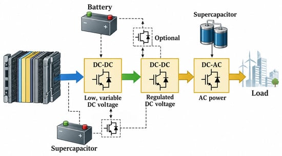
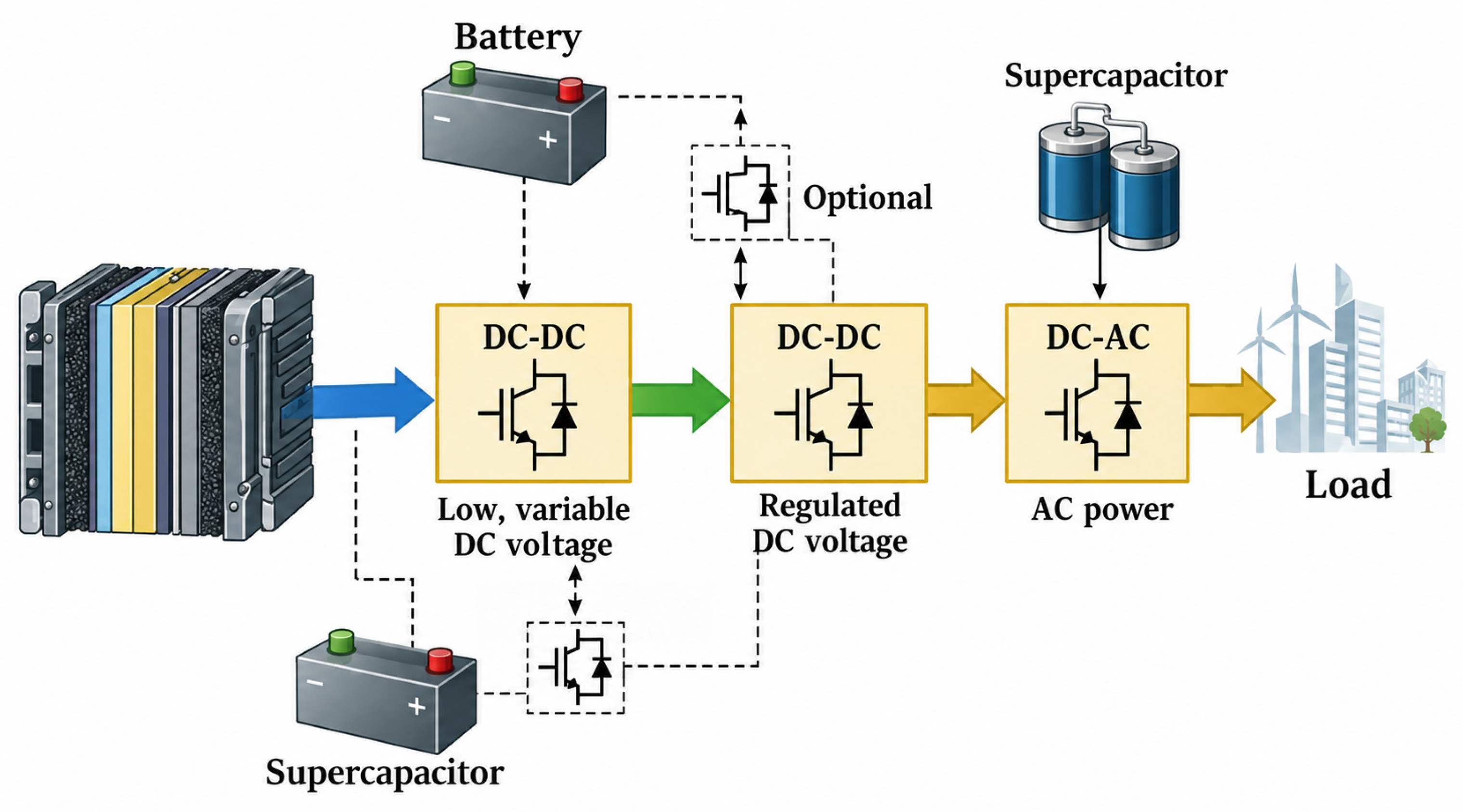
Power electronic converters constitute the primary interface between fuel cells and electrical loads or grids, enabling voltage regulation, power conditioning, and controlled energy transfer. Typical fuel cell systems employ DC–DC converters for voltage adaptation and current regulation, followed by DC–AC converters for AC load supply or grid connection (Figure 1). The design of these converters is subject to stringent requirements, including high efficiency, wide input voltage operating range, minimized input current ripple, fast transient performance, and high reliability, all of which directly influence system performance and fuel cell lifetime.
Figure 1.
Structure of a fuel cell system. The arrow colors are used only for visual distinction between the successive energy-conversion stages and have no additional technical meaning.
A substantial body of research has been devoted to the development of power converter topologies and control strategies tailored to fuel cell applications. Advances in power semiconductor devices, converter architectures, and control methods have resulted in a wide variety of proposed solutions with differing performance trade-offs. Consequently, a systematic and comprehensive review is required to synthesize existing knowledge, evaluate reported approaches, and identify prevailing trends and unresolved challenges. This report provides a comprehensive review of power converters for fuel cell systems, focusing on converter topologies, control techniques, and application-oriented considerations.
2. Proposed Classification Framework and Fuel Cell-Specific Converter Requirements
Fuel cell power conversion systems cannot be classified only by converter topology, since the appropriate converter interface depends simultaneously on the fuel cell type, voltage level, dynamic response, isolation requirement, load profile, and application domain [1,2,3]. Therefore, this review proposes a multi-criteria classification framework in which fuel cell power converters are categorized according to four complementary dimensions: (i) fuel cell technology, (ii) converter function, (iii) system architecture, and (iv) dominant design objective.
The proposed classification links the electrochemical and dynamic characteristics of the fuel cell with the corresponding power-electronic requirements [4,5]. In this framework, converter selection is not treated as a purely circuit-level problem, but as a system-level design decision involving voltage adaptation, current ripple mitigation, transient power support, galvanic isolation, and grid or load compatibility [6,7,8].
2.1. Proposed Classification Criteria
In this review, the classification of power converters for fuel cell systems is based on four interrelated criteria. The first criterion is the fuel cell technology, since proton-exchange membrane fuel cell (PEMFC), solid oxide fuel cell (SOFC), phosphoric acid fuel cell (PAFC), molten carbonate fuel cell (MCFC), alkaline fuel cell (AFC), and direct methanol fuel cell (DMFC) systems differ in operating temperature, dynamic response, voltage level, and typical application [9,10]. The second criterion is the converter function, including voltage step-up, galvanic isolation, bidirectional power flow, and DC–AC conversion [11,12]. The third criterion is the system architecture, which may be single stage, multi-stage, or hybridized with batteries and supercapacitors [13,14]. The fourth criterion is the dominant design objective, such as current ripple reduction, high voltage gain, efficiency improvement, grid compatibility, or lifetime extension [4,15,16].
This classification provides the basis for the subsequent analysis, where converter topologies are evaluated not only according to circuit structure, but also according to their suitability for specific fuel cell technologies and application requirements [10,11].
2.2. Fuel Cell Types and Converter Implications
Fuel cell technologies differ considerably in operating temperature, dynamic behavior, output voltage characteristics, and application domain [9,14]. These differences directly affect the requirements imposed on the power converter. For example, PEMFC systems used in transportation require fast current control and low input current ripple, whereas SOFC and MCFC systems are more relevant to stationary applications where slow thermal dynamics, isolation, reliability, and grid compatibility dominate the converter design [9,12,14].
The comparison in Table 1 shows that converter requirements cannot be generalized across all fuel cell systems. Low-temperature proton-exchange membrane fuel cell (PEMFC) and direct methanol fuel cell (DMFC) systems typically require compact and dynamically responsive DC–DC interfaces. In contrast, high-temperature solid oxide fuel cell (SOFC) and molten carbonate fuel cell (MCFC) systems are more commonly associated with stationary power generation, combined heat and power (CHP) applications, microgrids, and grid-oriented converter architectures, where slower power dynamics are generally acceptable [9,11,14].
Table 1.
Fuel cell type and corresponding converter requirements.
2.3. Converter-Relevant Fuel Cell Constraints
Fuel cells exhibit nonlinear voltage–current behavior, limited transient response, and sensitivity to current ripple [4,9]. These characteristics impose several converter-level constraints, including wide input voltage capability, controlled current dynamics, low input current ripple, and protection against overcurrent and undervoltage operation [10,11].
Unlike batteries, fuel cells should not be subjected to abrupt current variations, since rapid load changes may lead to voltage sag, reactant starvation, and accelerated degradation [12,13]. Consequently, fuel cell converters must ensure smooth current profiles, stable DC-link regulation, and coordinated interaction with energy storage devices such as batteries and supercapacitors [14].
These constraints justify the use of interleaved converter structures, high-gain topologies, soft-switching techniques, and hybrid power architectures, depending on the application domain and fuel cell technology [15,16].
2.4. Implications for the Proposed Converter Classification
The preceding discussion indicates that converter classification for fuel cell systems must consider both fuel cell characteristics and power-electronic functionality [9,10,11]. A topology that is suitable for a low-power PEMFC system may not be appropriate for a high-temperature SOFC or MCFC installation, even if the nominal voltage gain is similar [9,14]. Similarly, converters optimized for maximum efficiency may not provide the best solution when current ripple, galvanic isolation, transient response, or lifetime extension are dominant design objectives [4,12,16].
For this reason, the following sections evaluate converter topologies within the proposed multi-criteria framework. The analysis considers not only the circuit family, but also the application context, fuel cell type, control requirements, and expected trade-offs between efficiency, ripple mitigation, complexity, and reliability [10,11,16].
3. Review and Comparative Analysis of Converter Topologies
Power converter topologies for fuel cell systems are reviewed in this section according to the classification framework introduced in Section 2. In contrast to purely topology-oriented approaches, the discussion emphasizes the relationship between converter structure and fuel-cell-specific requirements, including voltage adaptation, current ripple mitigation, dynamic decoupling, galvanic isolation, and grid compatibility [10,11,15].
The objective is not only to summarize existing converter families, but also to evaluate their suitability for different fuel cell technologies and applications. Particular attention is given to the trade-offs between efficiency, voltage gain, ripple reduction, complexity, controllability, and reliability, since these factors ultimately determine the practical relevance of a given converter architecture [4,15,16].
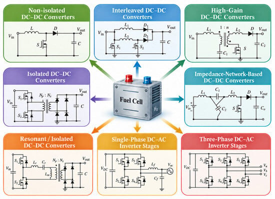
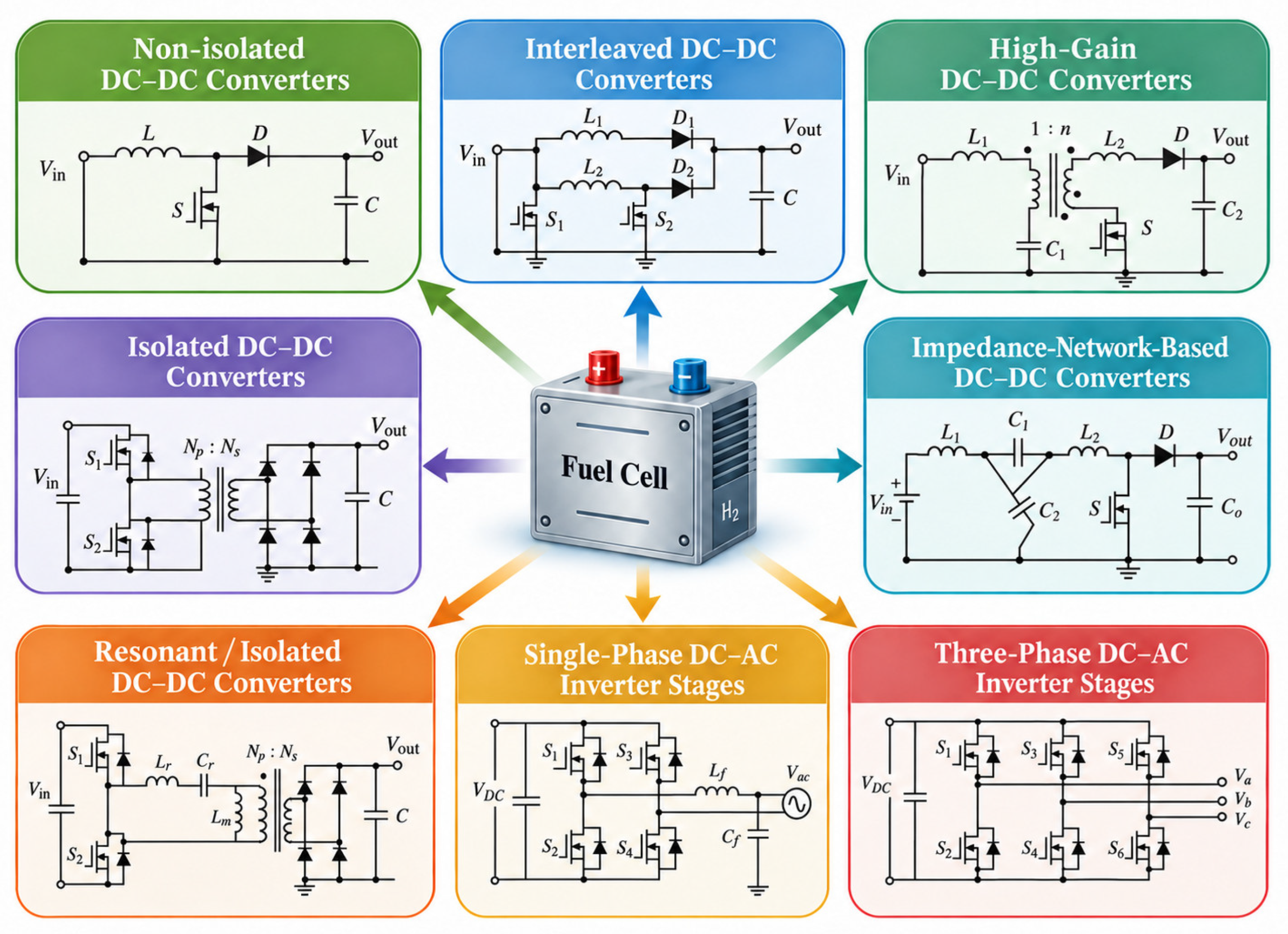
Figure 2 summarizes representative converter topologies considered in this review, including non-isolated, interleaved, high-gain, impedance-network-based, isolated DC–DC converters, and DC–AC inverter stages. These converter families are subsequently analyzed with respect to voltage gain, current ripple, isolation capability, control complexity, and application suitability.
Figure 2.
Representative power converter topologies for fuel cell systems according to the proposed classification framework.
3.1. Non-Isolated Converter Topologies
Non-isolated converters, particularly boost, buck–boost, Ćuk, and SEPIC structures, remain widely used in low- and medium-power fuel cell systems because of their simple structure, reduced component count and relatively straightforward control [4,10,16]. The conventional boost converter is frequently employed as a reference topology, since fuel cell stack voltages are typically lower than the required DC-link voltage. However, the practical suitability of conventional boost converters becomes limited when large voltage conversion ratios are required. Operation at high duty cycles increases conduction losses, semiconductor stress, and input current ripple, which negatively affect both converter performance and fuel cell durability [12]. Consequently, single-phase boost converters are generally more appropriate for low-power or cost-sensitive systems, whereas higher-power fuel cell applications increasingly rely on interleaved, high-gain, or isolated converter architectures.
Although non-isolated converters provide high efficiency and low implementation cost, they lack galvanic isolation and often require additional filtering to satisfy ripple-related constraints in PEMFC systems [13]. Therefore, their practical relevance strongly depends on application requirements, fuel cell type, and allowable current ripple levels.
3.2. Interleaved and Multiphase Converters
Interleaved converters are particularly relevant to fuel cell applications because they directly address input current ripple, current sharing and thermal disruption [1,5,15]. By phase-shifting multiple converter legs, ripple components at the fuel cell terminals can be partially cancelled, reducing electrical stress on the stack and improving current distribution among semiconductor devices.
Nevertheless, interleaving should not be interpreted as a universally superior solution. Its benefits depend on phase balancing, magnetic design, layout parasitics, semiconductor selection, and control synchronization. The increased number of switches, inductors, sensors, and control loops also raises cost and implementation complexity. Therefore, interleaved converters are most justified when ripple reduction and power scalability outweigh the penalties in hardware complexity.
3.3. High-Gain and Impedance-Network-Based Converters
High-gain DC–DC converters are used when the voltage mismatch between the fuel cell stack and the DC bus is large [1,6,16]. Coupled inductors, switched-capacitor cells, voltage multiplier cells, and impedance-network structures can provide higher voltage gain without requiring extreme duty cycles.
However, these approaches add passive components, increase component stress, and require more complex operating modes [3,4]. As a result, reported improvements in voltage gain must be assessed together with efficiency, reliability, thermal behavior, and controllability. In fuel cell systems, high-gain capability alone is insufficient unless the topology also maintains acceptable input current ripple and stable operation under dynamic load changes.
Impedance-network-based converters, including quasi-Z-source (qZS) structures, are attractive because they can provide voltage boosting and relatively favorable input current characteristics. However, their practical implementation requires careful consideration of startup behavior, passive component sizing, control complexity, and fault protection. Therefore, their suitability should be evaluated at system level rather than only by steady-state voltage gain [15,16].
3.4. Isolated and Resonant DC-DC Converters
Isolated DC–DC converters are preferred in high-power, high-voltage, and safety-critical fuel cell systems because they provide galvanic isolation and flexible voltage scaling through high-frequency transformers [7,8,10]. Common structures include push–pull, half-bridge, full-bridge, phase-shifted full-bridge, and resonant inductor–inductor–capacitor (LLC)-family converters.
Resonant converters are attractive because soft-switching operation can reduce switching losses and electromagnetic interference, supporting high-frequency and high-power-density operations. However, their performance is strongly dependent on resonant tank design, transformer parameters, input voltage variation, and load range. In fuel cell systems, this is particularly important because the converter must remain efficient and stable despite the stack’s wide operating voltage range.
Although isolated resonant converters offer clear advantages in efficiency and safety, they also require more complex design procedures, accurate parameter selection, and coordinated control with downstream stages. Therefore, they are especially suitable for stationary, grid-connected, and high-power fuel cell systems where isolation and efficiency outweigh cost and complexity penalties.
3.5. DC-AC Inverter Stages
DC–AC inverters represent a critical stage in fuel cell systems supplying AC loads or interfacing with utility grids [10]. In most practical architectures, the inverter is preceded by a regulated DC-link stage that decouples fuel cell dynamics from the AC side. Voltage-source inverters remain the dominant solution because of their mature control methods, compatibility with pulse-width modulation techniques, and suitability for grid-connected operation.
In grid-connected fuel cell systems, the inverter must satisfy additional requirements related to synchronization, harmonic distortion, reactive power support, fault ride-through capability, and compliance with grid-code requirements. Consequently, inverter design cannot be evaluated independently from the upstream DC–DC stage, since tightly regulated inverters may behave as constant power loads and destabilize the DC link.
Recent research increasingly focuses on inductor–capacitor–inductor (LCL) filter-based inverter interfaces, model-predictive current control, and wide-bandgap semiconductor implementation to improve switching performance, efficiency, and dynamic response. However, these improvements also increase control complexity, electromagnetic compatibility requirements, and thermal design challenges.
3.6. Comparative Assessment and Research Gaps
The large variety of converter topologies proposed for fuel cell applications demonstrates that converter selection cannot be based on voltage gain or efficiency alone. Instead, the suitability of a converter strongly depends on the trade-off between ripple mitigation, dynamic performance, galvanic isolation, implementation complexity, and application-specific operating requirements.
To provide a more systematic evaluation of the reviewed converter families, Table 2 summarizes the main characteristics of representative fuel cell converter topologies, including voltage gain capability, efficiency range, current ripple behavior, isolation capability, implementation complexity, and typical application domain.
Table 2.
Comparative assessment of converter topologies for fuel cell systems.
As indicated in Table 2, no converter topology is universally optimal for all fuel cell applications. Converter selection depends strongly on the trade-off between voltage gain, current ripple mitigation, efficiency, galvanic isolation, implementation complexity, and application-specific requirements.
Conventional boost converters remain attractive for low-power and cost-sensitive systems because of their simple structure and relatively high efficiency. However, their applicability becomes limited in medium- and high-power fuel cell systems due to increased current ripple and the high duty cycles required for large voltage gain. Interleaved architectures provide substantial ripple reduction and improved current sharing, making them particularly suitable for PEMFC applications, although these benefits are achieved at the expense of increased hardware and control complexity.
High-gain and impedance-network-based converters improve voltage adaptation capability, but frequently introduce higher semiconductor stress and more complicated operating modes. Similarly, isolated and resonant converters offer superior efficiency and galvanic isolation for stationary and grid-connected fuel cell systems, but require more sophisticated magnetic design and coordinated control strategies.
A major limitation of the existing literature is that many studies evaluate converter performance primarily in terms of voltage gain and peak efficiency, while degradation-related effects, thermal behavior, transient stability, and long-term reliability are often insufficiently investigated. Therefore, future comparative studies should adopt standardized benchmarking methodologies that include ripple characteristics, dynamic response, thermal stress, and lifetime-oriented performance indicators in addition to conventional efficiency measurements.
4. Control and Power Management Strategies
Control and power management strategies play a decisive role in FC systems, as they directly affect efficiency, dynamic performance, and fuel cell lifetime. Due to the nonlinear characteristics and limited dynamic response of fuel cells, conventional control approaches used in other energy conversion systems are often insufficient. Consequently, specialized control strategies have been developed to regulate voltage and current, minimize current ripple, and ensure safe and efficient operation under varying load conditions.
4.1. Voltage and Current Control Strategies
Voltage and current regulation constitutes the primary control objectives in fuel cell power converters. In most systems, DC–DC converters operate either in voltage-controlled mode, maintaining a regulated DC bus, or in current-controlled mode, directly shaping the fuel cell current profile [4].
Current-controlled operation is often preferred in fuel cell applications, as it allows direct limitation of fuel cell current and prevents excessive stress during transients. By regulating the input current of the converter, the fuel cell can be protected from rapid current variations and overcurrent conditions. However, current control generally requires accurate current sensing and fast inner control loops, increasing implementation complexity.
Voltage-controlled approaches, on the other hand, offer simpler implementation but may expose the fuel cell to uncontrolled current transients if not properly coordinated with additional protection mechanisms. As a result, many practical systems adopt cascaded control structures combining inner current loops with outer voltage regulation loops [6].
4.2. Maximum Power Point Tracking (MPPT)
MPPT strategies are widely employed to maximize energy extraction from fuel cell systems operating under variable conditions. Although fuel cells do not exhibit the same irradiance-dependent characteristics as photovoltaic systems, their optimal operating point varies with temperature, reactant supply, and aging [4].
Several MPPT techniques have been adapted for fuel cell applications, including perturb-and-observe (P&O), incremental conductance, and model-based methods. More recently, intelligent algorithms such as fuzzy logic controllers and artificial neural networks have been proposed to improve tracking accuracy and dynamic response [6].
Subbulakshmy et al. demonstrated that artificial neural network (ANN)-based maximum power point tracking (MPPT), combined with a high-gain interleaved DC–DC converter, can improve efficiency and reduce stress on the fuel cell in electric vehicle applications [6]. Nevertheless, MPPT algorithms introduce additional computational complexity and must be carefully tuned to avoid excessive current oscillations.
4.3. Model Predictive and AI-Based Control
Model predictive control (MPC) has gained increasing attention in fuel cell power conversion systems because it can explicitly handle multiple control objectives and operating constraints. Unlike conventional proportional–integral (PI)-based cascaded control, MPC can incorporate voltage limits, current constraints, switching states, and power-sharing requirements directly into the control formulation. This makes it suitable for hybrid fuel cell systems, where the fuel cell, battery, and supercapacitor must be coordinated under variable load conditions.
In fuel cell converter applications, MPC can improve transient response, DC-link regulation, and current limitation. However, its practical implementation is more demanding due to the need for accurate system models, higher computational effort, and careful tuning of prediction horizons and cost functions. These requirements become particularly important in multi-stage systems, where interactions between DC–DC converters, DC–AC inverters, and energy storage devices may affect stability.
AI-based control methods, including fuzzy logic controllers, ANNs, and AI-assisted MPPT algorithms, have also been investigated to improve adaptability under nonlinear and time-varying operating conditions. These methods are attractive because they can support faster tracking, adaptive power sharing, and reduced dependence on fixed mathematical models. Nevertheless, their practical use remains limited by training-data requirements, lack of interpretability, and insufficient long-term validation under realistic fuel cell operating profiles.
Therefore, MPC and AI-based methods should be considered promising emerging control approaches rather than fully mature industrial solutions. Future research should focus on experimentally validated controllers that combine constraint handling, degradation-aware operation, and computational feasibility for real-time fuel cell power conversion systems.
4.4. Ripple-Aware and Lifetime-Oriented Control
Given the sensitivity of fuel cells to current ripple, ripple-aware control strategies have gained increasing attention in recent literature. These approaches explicitly aim to minimize low-frequency and high-frequency ripple components through modulation techniques, interleaving phase management, or active filtering.
Lifetime-oriented control strategies extend this concept by incorporating fuel cell degradation models or empirical constraints into the control design. Instead of operating the fuel cell solely at maximum efficiency or power, such strategies prioritize smooth current profiles and reduced stress, thereby extending system lifetime.
Mercier et al. highlighted the importance of considering semiconductor technology and converter sizing jointly with control objectives to achieve ripple reduction and improved durability in fuel cell power architectures [12].
4.5. Power Management in Hybrid Fuel Cell Systems
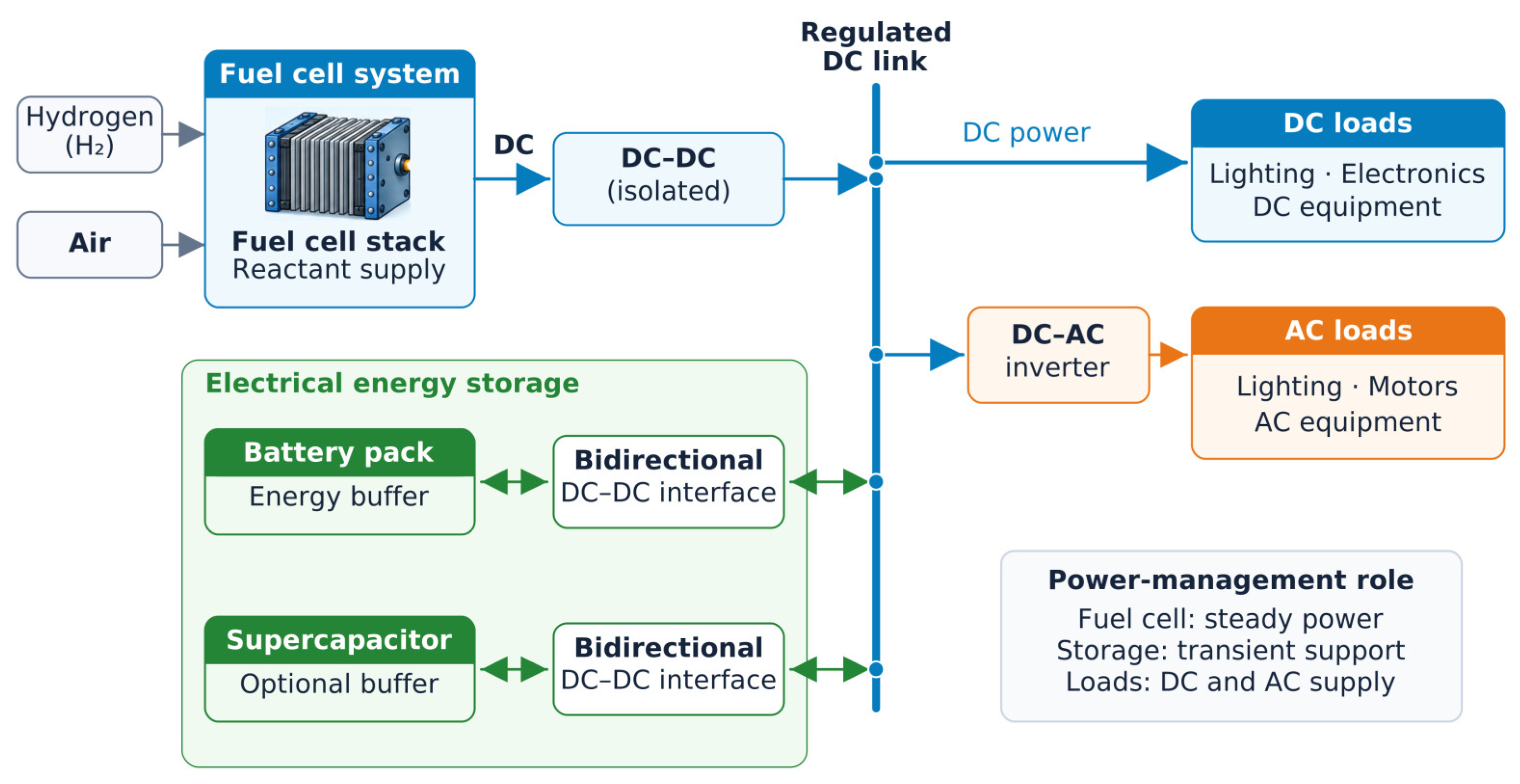
In hybrid fuel cell systems incorporating auxiliary energy storage elements, power management strategies are required to coordinate energy flow among the fuel cell, storage devices, and load. Their structure is shown in Figure 3. Typically, the fuel cell is operated near a quasi-steady operating point, while batteries or supercapacitors supply transient power demands.
Figure 3.
Functional architecture of a hybrid fuel cell power system supplying DC and AC loads. Gray arrows indicate reactant supply, blue arrows indicate DC power flow, green double-headed arrows indicate bidirectional power exchange with electrical energy storage, and orange arrows indicate AC power flow. Auxiliary components and control signals are omitted for clarity.
Power management algorithms may be rule-based, optimization-based, or predictive, depending on system complexity and application requirements. Effective power management reduces fuel cell stress, improves system efficiency, and enhances overall reliability. However, it also increases control complexity and demands accurate system modeling and sensing.
4.6. Stability and Interaction with Downstream Converters
Fuel cell power converters often operate in multi-stage architectures, where interactions between DC–DC converters and downstream DC–AC inverters can affect system stability. In particular, constant power load behavior imposed by tightly regulated inverters may introduce negative impedance effects, potentially leading to oscillations or instability [8].
Recent studies emphasize the need for coordinated control design and impedance-based stability analysis to ensure robust operation across the full operating range. Advanced control strategies, including adaptive and model-predictive control, have been proposed to address these challenges, although their practical implementation remains an active research topic [8].
4.7. Summary and Open Issues
The reviewed control and power management strategies demonstrate that effective converter control is essential for achieving high efficiency, low ripple, and extended fuel cell lifetime. While conventional voltage and current control methods remain widely used, recent research increasingly emphasizes ripple-aware, lifetime-oriented, and hybrid-system-oriented control approaches.
Open challenges include the development of unified control frameworks that simultaneously address efficiency, durability, and system stability, as well as the experimental validation of advanced control strategies under long-term, fuel cell-relevant operating conditions.
5. Key Challenges Identified in the Literature
Despite significant progress in power converter technologies for FC systems, the literature consistently reports a number of unresolved technical challenges that limit performance, reliability, and large-scale deployment. These challenges arise from the intrinsic characteristics of fuel cells, the increasing complexity of power electronic interfaces, and the stringent requirements imposed by modern applications.
5.1. Trade-Offs Between Efficiency, Complexity, and Cost
One of the most frequently discussed challenges is the trade-off between converter efficiency, circuit complexity, and implementation cost. High-efficiency solutions such as interleaved, high-gain, or resonant isolated converters generally require a larger number of components, more complex control schemes, and careful magnetic design.
While such solutions can significantly improve performance metrics such as ripple reduction and power density, they also increase system cost and design effort. Conversely, simpler topologies, such as single-phase boost converters, offer lower cost and ease of implementation but fail to meet performance and durability requirements in medium- and high-power fuel cell systems [4]. Achieving an optimal balance among these competing factors remains a key design challenge.
5.2. Fuel Cell Degradation and Lifetime Concerns
Fuel cell lifetime is strongly influenced by electrical operating conditions, particularly current ripple, transient loading, and prolonged operation outside optimal regions. Numerous studies indicate that excessive ripple and frequent current fluctuations accelerate degradation mechanisms such as catalyst aging, membrane stress and reactant starvation, especially in PEMFC systems.
Although many converter designs aim to minimize ripple and smooth fuel cell current, long-term experimental validation under realistic operating conditions is often lacking. As a result, the actual impact of advanced converter topologies and control strategies on fuel cell lifetime remains insufficiently quantified in the literature. This gap complicates the comparison of different solutions and limits confidence in their long-term benefits.
5.3. Thermal Management and Power Density
The pursuit of higher power density in fuel cell power converters introduces additional challenges related to thermal management. Increased switching frequencies, higher current levels, and compact packaging and reduced passive component value can lead to elevated thermal stress on semiconductor devices, magnetic components and capacitors.
The adoption of wide-bandgap semiconductor devices has enabled higher switching frequencies and reduced losses; however, it also imposes stricter requirements on thermal design and electromagnetic compatibility. Inadequate thermal management can negate the efficiency gains achieved through advanced converter topologies, making thermal considerations a critical aspect of practical system design.
5.4. Electromagnetic Interference and Power Quality
Electromagnetic interference (EMI) and power quality issues become increasingly pronounced as converter switching frequencies and system complexity increase. Fuel cell systems are particularly sensitive to conducted and radiated EMI due to their low-voltage, high-current nature, which increases the impact of parasitic inductances, switching transients, and input current ripple.
While interleaving and soft-switching techniques can reduce EMI, they do not eliminate the need for careful filtering, layout optimization, and compliance with electromagnetic standards. Balancing EMI mitigation with efficiency and size constraints remains an open challenge, especially in automotive and grid-connected applications.
5.5. Stability in Multi-Stage and Hybrid Architectures
Modern fuel cell systems frequently employ multi-stage power conversion architectures and hybrid configurations incorporating batteries or supercapacitors. In such systems, interactions between converters can lead to stability issues, particularly when downstream converters exhibit constant power load behavior.
Impedance mismatches, control loop interactions, and time-scale separation between fuel cells and auxiliary storage devices complicate stability analysis and controller design. Although impedance-based modeling and coordinated control approaches have been proposed, their application to complex, real-world fuel cell systems remains an active research area.
5.6. Lack of Standardized Evaluation and Benchmarking
A recurring issue in the reviewed literature is the lack of standardized evaluation criteria and benchmarking procedures. Converter performance is often reported under different operating conditions, ripple limits, and load profiles, making direct comparison between studies difficult.
Furthermore, metrics such as long-term reliability, degradation rate, and lifetime extension are rarely assessed in a consistent manner. The absence of unified benchmarks limits the ability to objectively assess the relative merits of competing converter topologies and control strategies and hinders technology transfer to industrial.
5.7. Summary of Key Challenges
In summary, the major challenges identified in the literature include balancing efficiency with complexity and cost, mitigating fuel cell degradation, managing thermal and EMI issues, ensuring stability in multi-stage and hybrid systems, and establishing standardized evaluation methodologies. Addressing these challenges requires a holistic design approach that integrates converter topology, control strategy, thermal management, and system-level considerations.
These issues motivate ongoing research into advanced converter architectures, intelligent control strategies, and emerging technologies, which are discussed in the following section.
6. Applications and Industrial Implementations
Power electronic converters for fuel cell systems have been developed and deployed across a wide range of applications, driven by requirements for clean energy, high efficiency, and reliability. While many converter topologies and control strategies are proposed at the laboratory level, their practical relevance depends on application-specific constraints such as power level, safety standards, dynamic performance, and cost. This section reviews the main application domains of fuel cell power converters and highlights representative industrial implementation trends reported in the literature.
6.1. Transportation Applications
Transportation is one of the most demanding application areas for fuel cell power converters, particularly in FCEVs, buses, and auxiliary power units. In these systems, converters must handle wide input voltage variations, rapid load transients, and strict constraints on efficiency, size, and weight.
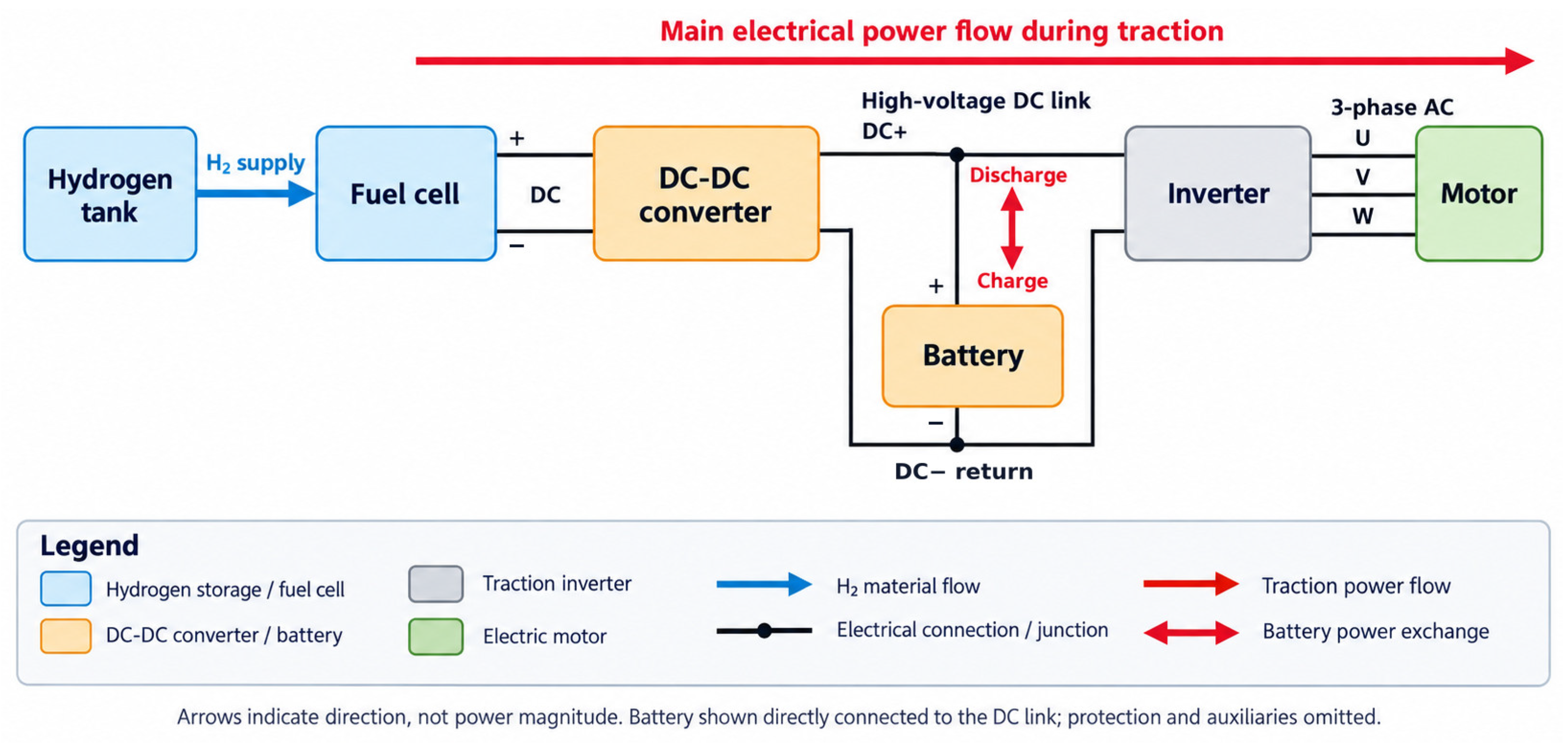
DC–DC converters in transportation applications are typically designed to step up the low fuel cell stack voltage to a high-voltage DC bus, which supplies traction inverters and auxiliary loads (Figure 4). Interleaved and high-gain converter topologies are frequently adopted to reduce input current ripple and improve power density [1]. Hybrid architectures combining fuel cells with batteries or supercapacitors are also widely used to support acceleration and regenerative braking, placing additional demands on coordinated power management strategies [6].
Figure 4.
Block diagram of a fuel-cell/battery hybrid electric powertrain. The blue arrow indicates hydrogen supply, black lines and dots represent electrical connections and junctions, and red arrows indicate the main traction power-flow direction and bidirectional battery power exchange. Blue blocks represent hydrogen storage and the fuel cell; orange blocks represent the DC–DC converter and battery; the gray block represents the traction inverter; and the green block represents the electric motor. Arrows indicate direction rather than power magnitude. The battery is shown directly connected to the DC link; protection devices and auxiliary systems are omitted.
Industrial implementations emphasize robustness, fault tolerance, and compliance with automotive standards, often favoring proven converter architectures over highly optimized but complex solutions.
6.2. Stationary Power Generation Systems
Stationary fuel cell systems are employed for distributed generation, combined heat and power (CHP), and backup power applications. These systems typically operate at higher power levels and more stable load conditions compared to transportation applications, allowing greater flexibility in converter design.
Isolated DC–DC converters and DC–AC inverters are commonly used to interface stationary fuel cell systems with AC loads or utility grids. Resonant and soft-switching converter topologies are increasingly favored due to their high efficiency and reduced electromagnetic interference [7]. In grid-connected systems, power converters must comply with grid codes related to power quality, synchronization, and fault ride-through capability, which strongly influences control strategy selection [8].
From an industrial perspective, stationary systems prioritize long-term reliability, ease of maintenance, and lifetime cost over maximum power density, leading to conservative design choices and extensive protection mechanisms.
6.3. Backup and Auxiliary Power Systems
Fuel cells are increasingly used in backup and auxiliary power applications, such as telecommunications infrastructure, data centers, and emergency power supplies. In these applications, converters must ensure high availability, fast startup, and seamless transition between operating modes.
DC–DC converters are often used to regulate fuel cell output voltage and charge intermediate energy storage elements, while DC–AC inverters supply critical AC loads. Converter designs in backup systems typically emphasize simplicity, reliability, and fault tolerance rather than advanced optimization.
Hybrid configurations with batteries are common to ensure uninterrupted power during fuel cell startup or transient load changes. As a result, power management strategies must coordinate multiple energy sources while maintaining system stability and power quality [8].
6.4. Microgrids and Grid-Connected Applications
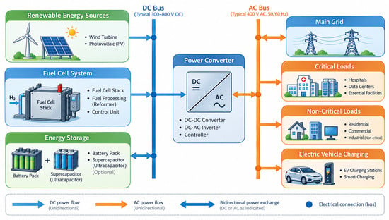
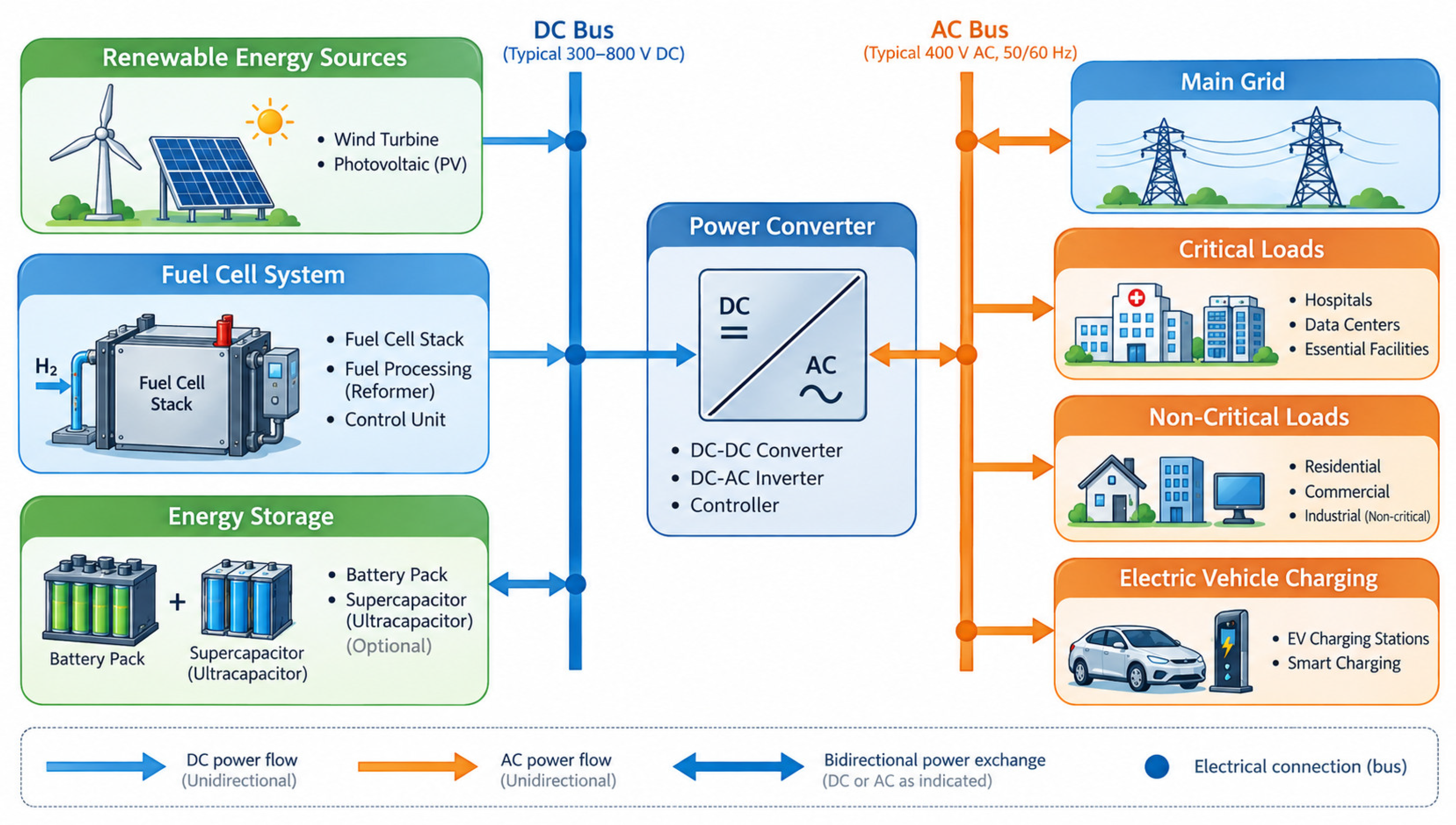
Fuel cell systems are increasingly integrated into microgrids and distributed energy systems, where they operate alongside renewable energy sources and energy storage. In such applications, power converters play a key role in voltage regulation, power sharing, and grid support functions—Figure 5.
Figure 5.
Fuel cell system microgrid application.
Grid-connected inverters interfacing fuel cell systems must support bidirectional power flow, reactive power control, and compliance with grid regulations. Advanced control techniques are often required to manage interactions with other distributed energy resources and maintain microgrid stability.
Recent industrial demonstrations emphasize modular and scalable converter architectures that facilitate system expansion and redundancy, aligning with trends toward decentralized energy systems.
6.5. Gap Between Laboratory Prototypes and Industrial Systems
A recurring theme in the literature is the gap between laboratory-scale converter prototypes and industrial fuel cell systems. Academic studies often prioritize efficiency, voltage gain, or ripple reduction under controlled conditions, whereas industrial implementations must address additional constraints such as manufacturability, cost, certification, and long-term reliability.
Consequently, only a subset of proposed converter topologies is adopted in commercial systems. Bridging this gap requires closer collaboration between academia and industry, as well as standardized testing and validation methodologies that reflect real-world operating conditions.
6.6. Summary of Application-Specific Requirements
In summary, different fuel cell applications impose distinct requirements on power converter design. Transportation systems prioritize power density and dynamic performance, stationary systems emphasize efficiency and reliability, backup systems focus on availability and simplicity, and microgrids require advanced grid-interactive capabilities. These diverse requirements underscore the importance of application-oriented converter selection and motivate the discussion and synthesis presented in the following section.
7. Conclusions
This review has examined power converters for fuel cell systems, covering fuel cell characteristics, converter classification, topologies, control strategies and applications. The analysis confirms that the low and variable output voltage, limited dynamic response, and sensitivity to current ripple of fuel cells impose stringent requirements on power electronic interfaces.
The literature shows that no single converter topology is universally optimal. Conventional non-isolated converters remain suitable for low-power systems, while interleaved and high-gain structures are preferred where ripple reduction and voltage adaptation are critical. Isolated and resonant converters dominate high-power and grid-connected applications due to their efficiency and safety advantages. Control and power management strategies play a key role in ensuring stable operation and extending fuel cell lifetime, with recent emphasis on ripple-aware and lifetime-oriented approaches.
Future research should focus on integrated co-design of converter topology and control, standardized performance evaluation, and long-term experimental validation to support reliable and scalable fuel cell power conversion systems.
Author Contributions
Conceptualization, N.H., R.K. and P.S.; Methodology, N.H., and P.S.; Software, R.K. and P.S.; Validation, P.S.; Formal analysis, N.H., R.K. and P.S.; Investigation, P.S.; Resources, R.K. and P.S.; Data curation, P.S.; Writing—original draft, R.K. and P.S.; Writing—review and editing, N.H., R.K. and P.S.; Visualization, N.H., R.K. and P.S.; Supervision, N.H. and P.S.; Project administration, N.H.; Funding acquisition, N.H. All authors have read and agreed to the published version of the manuscript.
Funding
This work was supported by the European Regional Development Fund under the “Research Innovation and Digitization for Smart Transformation” program 2021–2027 under Project BG16RFPR002-1.014-0006 “National Centre of Excellence Mechatronics and Clean Technologies”, and the APC was funded by Project BG16RFPR002-1.014-0006.
Institutional Review Board Statement
Not applicable.
Informed Consent Statement
Not applicable.
Data Availability Statement
The original contributions presented in this study are included in the article. Further inquiries can be directed to the corresponding authors.
Acknowledgments
During the preparation of this manuscript, the authors used OpenAI ChatGPT, based on the GPT-5 model solely for language editing, proofreading, grammatical correction, and improvement of clarity and academic style. All scientific content, methodology, analysis, results, conclusions, figures, and references were developed and verified by the authors, who take full responsibility for the content of the manuscript.
Conflicts of Interest
The authors declare no conflicts of interest.
Abbreviations
The following abbreviations are used in this manuscript:
| AFC | Alkaline Fuel Cell |
| ANN | Artificial Neural Network |
| AC | Alternating Current |
| CHP | Combined Heat and Power |
| DC | Direct Current |
| DMFC | Direct Methanol Fuel Cell |
| EMI | Electromagnetic Interference |
| FC | Fuel Cell |
| FCEV | Fuel Cell Electric Vehicle |
| MCFC | Molten Carbonate Fuel Cell |
| MPC | Model Predictive Control |
| MPPT | Maximum Power Point Tracking |
| P&O | Perturb and Observe |
| PAFC | Phosphoric Acid Fuel Cell |
| PEMFC | Proton Exchange Membrane Fuel Cell |
| PI | Proportional–integral |
| qZS | quasi-Z-source |
| SOFC | Solid Oxide Fuel Cell |
| VSI | Voltage Source Inverter |
References
- Larminie, J.; Dicks, A. Fuel Cell Systems Explained, 2nd ed.; Wiley: Chichester, UK, 2003. [Google Scholar] [CrossRef] [Scilit]
- Yu, X.; Starke, M.R.; Tolbert, L.M.; Ozpineci, B. Fuel cell power conditioning for electric power applications: A summary. IET Electr. Power Appl. 2007, 1, 643–656. [Google Scholar] [CrossRef] [Scilit]
- Ali, M.S.; Kamarudin, S.K.; Masdar, M.S.; Mohamed, A. An overview of power electronics applications in fuel cell systems: DC and AC converters. Sci. World J. 2014, 2014, 103709. [Google Scholar] [CrossRef] [Scilit]
- Wahdame, B.; Girardot, L.; Hissel, D.; Harel, F.; François, X.; Candusso, D.; Péra, M.-C.; Dumercy, L. Impact of power converter current ripple on the durability of a fuel cell stack. In Proceedings of the IEEE International Symposium on Industrial Electronics (ISIE); IEEE: New York, NY, USA, 2008; pp. 1495–1500. [Google Scholar] [CrossRef] [Scilit]
- Parache, F.; Schneider, H.; Turpin, C.; Richet, N.; Debellemanière, O.; Bru, É.; Thieu, A.T.; Bertail, C.; Marot, C. Impact of Power Converter Current Ripple on the Degradation of PEM Electrolyzer Performances. Membranes 2022, 12, 109. [Google Scholar] [CrossRef] [Scilit]
- Qasem, N.A.A.; Abdulrahman, G.A.Q. A recent comprehensive review of fuel cells: History, types, and applications. Int. J. Energy Res. 2024, 2024, 7271748. [Google Scholar] [CrossRef] [Scilit]
- Das, V.; Padmanaban, S.; Venkitusamy, K.; Selvamuthukumaran, R.; Blaabjerg, F.; Siano, P. Recent advances and challenges of fuel cell based power system architectures and control—A review. Renew. Sustain. Energy Rev. 2017, 73, 10–18. [Google Scholar] [CrossRef] [Scilit]
- Hosseinpour, M.; Seifi, E.; Seifi, A.; Shahparasti, M. Design and analysis of an interleaved step-up DC–DC converter with enhanced characteristics. Sci. Rep. 2024, 14, 14413. [Google Scholar] [CrossRef] [Scilit]
- Preethiraj, P.M.; Belwin Edward, J. Design of novel DC–DC interleaved boost converter for BLDC application. Heliyon 2024, 10, e40041. [Google Scholar] [CrossRef] [Scilit]
- Rashid, R.; Baghramian, A.; Mojallali, H. Quasi-Z-source interleaved DC–DC converter for fuel cell vehicle application. IET Power Electron. 2024, 17, 2741–2770. [Google Scholar] [CrossRef] [Scilit]
- Kumar, S.; Jammeh, S.; Samb, R.; Singh, A. Efficient DC–DC power converters for fuel-cell electric vehicle: A qualitative assessment. IET Power Electron. 2024, 17, 3166–3204. [Google Scholar] [CrossRef] [Scilit]
- Mercier, V.; Azib, T.; Ceschia, A.; Larouci, C. Influence of wide-bandgap semiconductors in interleaved converters sizing for a fuel-cell power architecture. World Electr. Veh. J. 2024, 15, 148. [Google Scholar] [CrossRef] [Scilit]
- Subbulakshmy, R.; Palanisamy, R.; Alshahrani, S.; Saleel, C.A. Implementation of Non-Isolated High Gain Interleaved DC-DC Converter for Fuel Cell Electric Vehicle Using ANN-Based MPPT Controller. Sustainability 2024, 16, 1335. [Google Scholar] [CrossRef] [Scilit]
- Zaikin, D.I.; Andersen, M.K.; Rugholt, M.B.R.; Kjeldsen, T.K.; Davari, P. Optimized design of multi-channel resonant converter for fuel cell application. IEEE Access 2024, 12, 66605–66624. [Google Scholar] [CrossRef] [Scilit]
- Alavi, O.; Rajabloo, T.; De Ceuninck, W.; Daenen, M. Non-Isolated DC-DC Converters in Fuel Cell Applications: Thermal Analysis and Reliability Comparison. Appl. Sci. 2022, 12, 5026. [Google Scholar] [CrossRef] [Scilit]
- Das, H.S.; Tan, C.W.; Yatim, A.H.M. Fuel cell hybrid electric vehicles: A review on power conditioning units and topologies. Renew. Sustain. Energy Rev. 2017, 76, 268–291. [Google Scholar] [CrossRef] [Scilit]

Disclaimer/Publisher’s Note: The statements, opinions and data contained in all publications are solely those of the individual author(s) and contributor(s) and not of MDPI and/or the editor(s). MDPI and/or the editor(s) disclaim responsibility for any injury to people or property resulting from any ideas, methods, instructions or products referred to in the content. |
© 2026 by the authors. Licensee MDPI, Basel, Switzerland. This article is an open access article distributed under the terms and conditions of the Creative Commons Attribution (CC BY) license.