


Abstract
This paper investigates the position drift in a stepper motor used within a part feeding system for the orientation of cylindrical components. The system employs a bowl feeder, orientation sensors, and an indexing mechanism with eight precise positions at 45° intervals. During commissioning, a gradual deviation between the theoretical and actual angular positions of the stepper mechanism was observed, leading to operational interruptions. Experimental tests were conducted to analyze the source of the drift by comparing theoretical and encoder-based angular positions over a large number of repetitions. The results revealed a small but cumulative positioning error caused by the recursive generation of new setpoints from encoder feedback. To eliminate this effect, an improved control strategy was implemented, where each new setpoint is calculated from the previous theoretical value. This modification effectively eliminates the accumulation of measurement variations and prevents long-term drift. Experimental validation demonstrated a significant improvement in long-term positioning accuracy, reducing the total deviation to approximately 0.1–0.2° and enabling stable system operation over extended periods. The proposed solution is simple to implement and enhances the reliability and precision of automated part feeding systems.
1. Introduction
Traditional part feeding systems often include a vibratory bowl feeder which orients the parts in a state and position that is suitable for the automation process. These systems are proven and offer sufficient reliability at a reasonable cost. Such automated systems are widely used in industrial and robotic applications, where positioning accuracy is critical for reliable operation [1].
There is a group of parts that could be oriented only by the physical difference between their sides. Often there are holes on both sides which differ in diameter and/or position and this is used for their orientation by a fixed pin that allows for only the bigger diameter. By means of two sensors the system decides whether the part is properly oriented or not. Then, a stepper motor is used to transport the part one step further. Stepper motors are widely applied in indexing and positioning tasks; however, their positioning accuracy is strongly influenced by control strategies, signal generation methods, and tracking performance [2,3,4]. In addition, system dynamics and drive behavior under varying load conditions may further affect positioning stability and long-term accuracy [5,6]. In the end, all parts are oriented in the desired position and state. Furthermore, measurement uncertainty and error propagation in dynamic systems are known to contribute to cumulative positioning deviations over repeated cycles [7,8,9].
2. Materials and Methods
Analysis of the System
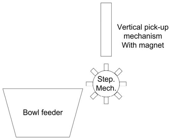
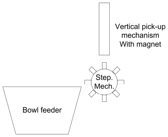
A system with a bowl feeder (NDP250, KMS Engineering Ltd., Plovdiv, Bulgaria) and a stepper motor (EMMT-ST-57-M-RS, Festo SE & Co. KG, Esslingen am Neckar, Germany) is used to orient cylindrical parts that have a hole on the one side and a solid surface on the other side. The parts are oriented by means of two sensors—S1 and S2. S1—part presence, S2—correct position. By a certain delay of S1, the system analyzes the state of S2 and activates a rotation of the stepper mechanism, or a blowout nozzle. A concept of the process is shown in Figure 1.
Figure 1.
Concept of the process.
The stepper mechanism features 8 precise pins, each located at 45°. This allows for shorter steps and faster productivity.
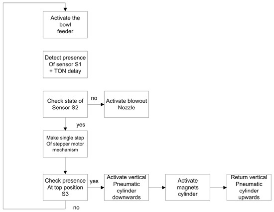
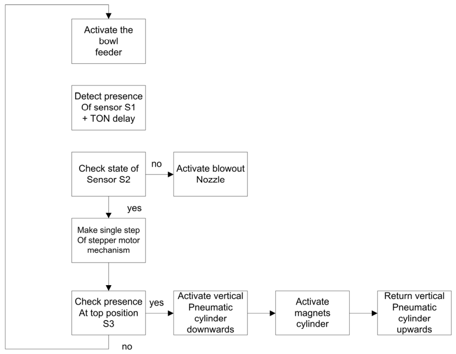
The algorithm is relatively simple. When the system is empty (there is no part presence), the bowl feeder is started. Once a part is detected by sensor S1 the system waits for a predefined Timer On-Delay(TON-delay) and when it is elapsed, it checks for the status of sensor S2. If the signal is present, it means the part is properly oriented on the precise pin and thus the sensor S2 detects it. The system proceeds with a single step of the stepper mechanism. In the opposite case (logical 0 of S2), a blowout nozzle with predefined blowout time is activated which returns the part in the bowl.
The pick-up system consists of a vertical pneumatic cylinder (SLF-16-40-P-A, Festo SE & Co. KG, Esslingen am Neckar, Germany) and a cylinder (ADVUL-12-25-P-A, Festo SE & Co. KG, Esslingen am Neckar, Germany) that controls permanent magnets which are used to hold the part as it is delicate and the use of a classical mechanical gripper is impractical. Upon presence of part at top position (12 o’clock of the stepper mechanism), the vertical cylinder is moved downwards, the magnets are activated and the vertical cylinder is returned back up. Figure 2 demonstrates the algorithm workflow graphically.
Figure 2.
Algorithm of the process.
3. Results and Discussion
3.1. Practical Challenges of the Tuning Process
After the system is built, it is concluded that the right synchronization between several parameters is important for the achievement of the highest productivity of the system. Among the important parameters are:
- Bowl feeder output voltage (OV)—directly affecting the parts movement speed
- TON delay for inspection of sensor S1 (t1)
- Blowout time for the nozzle (t2)
The output voltage controls the feed rate of the bowl feeder. It is important that only a single part is present in front of S1 at a time. The last sector of the mechanical pathway is designed in such a way that it accelerates the single part towards the sensor.
Timer t1 should be directly related to the output voltage. The time for detection is part of the waiting time where only a single part is present. The reason for this is that if a second part is present immediately after the currently inspected one, a potential blowout will remove both of them from the pathway and this is a great reduction of the productivity as the second part may be properly oriented.
The blowout time t2 should be minimal to avoid blowing out the next part, regardless of its exact position—immediately after the part, or slightly backwards.
Additional parameters that do not directly affect the orientation process but still are to be considered are:
- Speed of rotation of the stepper mechanism
- Duration of the pick-up process
These parameters are not independent as the stepper motor cannot make steps while the pick-up process takes place as there is a mechanical collision between the rotation mechanism and the pick-up mechanism.
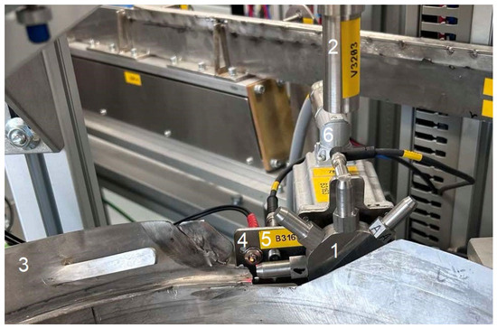
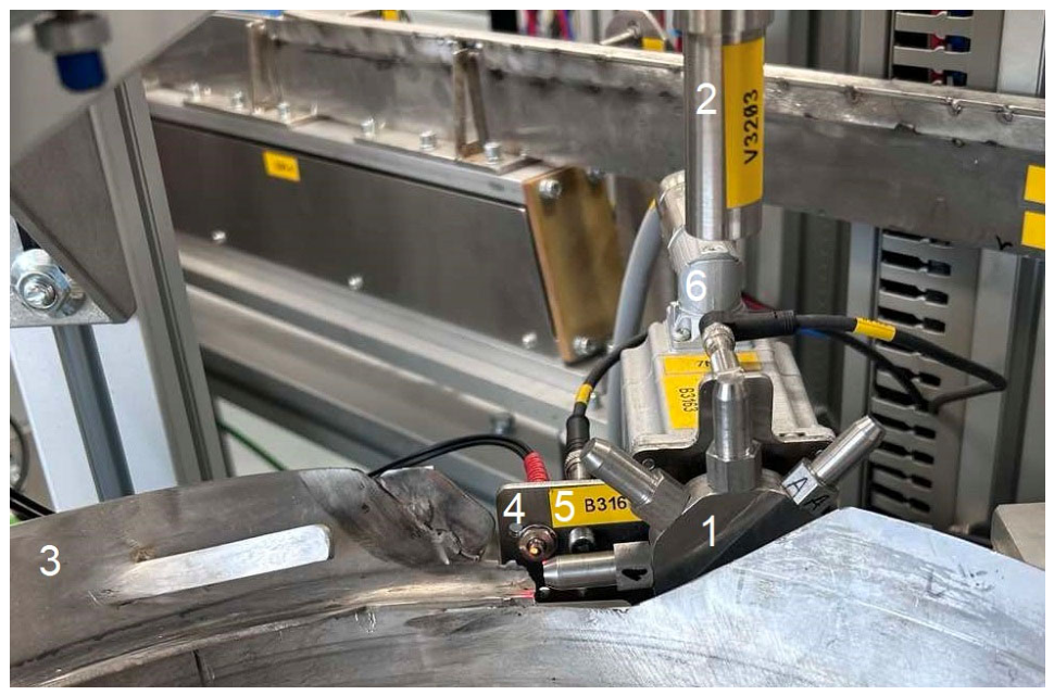
The developed system is shown in Figure 3. A vibratory bowl feeder (pos. 3) feeds the parts towards a rotating disc (pos. 1). Sensor S1 (pos. 4) is a fiber-beam reflection sensor (FFRX-610, F&C Sensing Technology Co. Ltd, Changsha, China) that is used together with a fiber amplifier (FF403P/D, F&C Sensing Technology Co. Ltd, Changsha, China) that is preset to detect parts when they are present (logical 1) and to provide logical 0 when there are no parts in front of the sensor. Sensor S2 (pos. 5) is an inductive proximity switch (IB080173, IPF Electronic GmbH, Altena, Germany) which only detects properly oriented parts. The nominal distance of this sensor is about 2 mm which perfectly suits the parts. The vertical cylinder is tagged as V3201 and the magnets cylinder is tagged as V3203 (pos. 2). The stepper motor(pos. 6) features an absolute single-turn encoder in order to precisely know the current position. The accuracy of the picking depends on:
Figure 3.
A picture of the developed system: 1—rotating disc 2—magnets cylinder; 3—vibratory bowl feeder; 4—sensor S1; 5—sensor S2; 6—stepper motor.
- Mechanical precision of the stepper part and the deviation between the individual pins
- The accuracy of the stepper motor single steps
These factors are closely related to mechanical loading conditions and structural behavior, which may influence system precision and long-term stability [10,11].
Despite the properly determined tolerances and form deviations, the concept would always lead to a drift in position due to the aforementioned parameters as well as due to unknown random factors. From functional point of view, the system is tolerant to about 1.5°–3° drift of the mechanical position between the stepper mechanism and the pick-up mechanism. In case a greater drift is achieved, it will make it impossible to pick up a part and the system will stop.
3.2. Key Issue with Stepper Motor Position
After the system is commissioned and first trials are made it becomes clear that after a certain period of time the position drifts and the system stops. The drift is about three degrees and gradually increases. The only fix is to make the stepper drive find the home position again and restart the system. However, after approximately another 30 min, it blocks again. An investigation has been made in order to find the reasons for this.
In the beginning, the calculation of the new position used Equation (1).
NP = CP + 45.00°
NP—new position setpoint, CP—current position feedback from encoder
At a glance, this looks correct—the position is determined from the current position + 45°. However, similar feedback-based approaches may introduce cumulative positioning deviations when small measurement errors are recursively propagated [3,4]. In order to investigate the problem, a special testing program has been developed that only rotates the mechanism with all other devices and sensors disabled. It counts the number of revolutions and shows the actual position of the stepper drive.
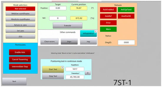
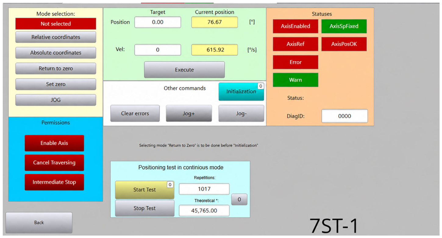
Figure 4 shows a screenshot from the developed system for the HMI. The main elements are Start and Stop buttons, a numerical field for the number of revolutions (repetitions) of the test, fields for the theoretical angle after the amount of repetitions and the current stepper setpoint. Also, the current position (encoder feedback), the velocity setpoint and the current feedback for velocity are visualized.
Figure 4.
A screenshot of the developed HMI software.
The aim of the test is to rotate the system as many times as possible and to observe and compare the results between the theoretical angle and the real feedback angle. Several tests have been conducted and the results are present in Table 1.
Table 1.
Experiments for the investigation of the problem.
The results show a small and consistent negative deviation between the theoretical and measured angular positions of the stepper motor. This deviation arises from the method used to calculate successive setpoints in Equation (1).
Because the encoder feedback contains a small measurement variation (typically within ±0.05° relative to the theoretical position), this variation accumulates over multiple repetitions, leading to a gradual increase in the overall positioning error. Despite this accumulation, the relative error remains very small, and the system demonstrates good repeatability and stable performance.
Due to mechanical vibrations and other disturbances, the encoder feedback exhibits small random variations within the allowable tolerance range. As a result, a relatively long period (approximately 30 mins) is required for the drift to become noticeable, as some deviations are partially compensated over time [12].
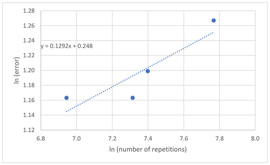
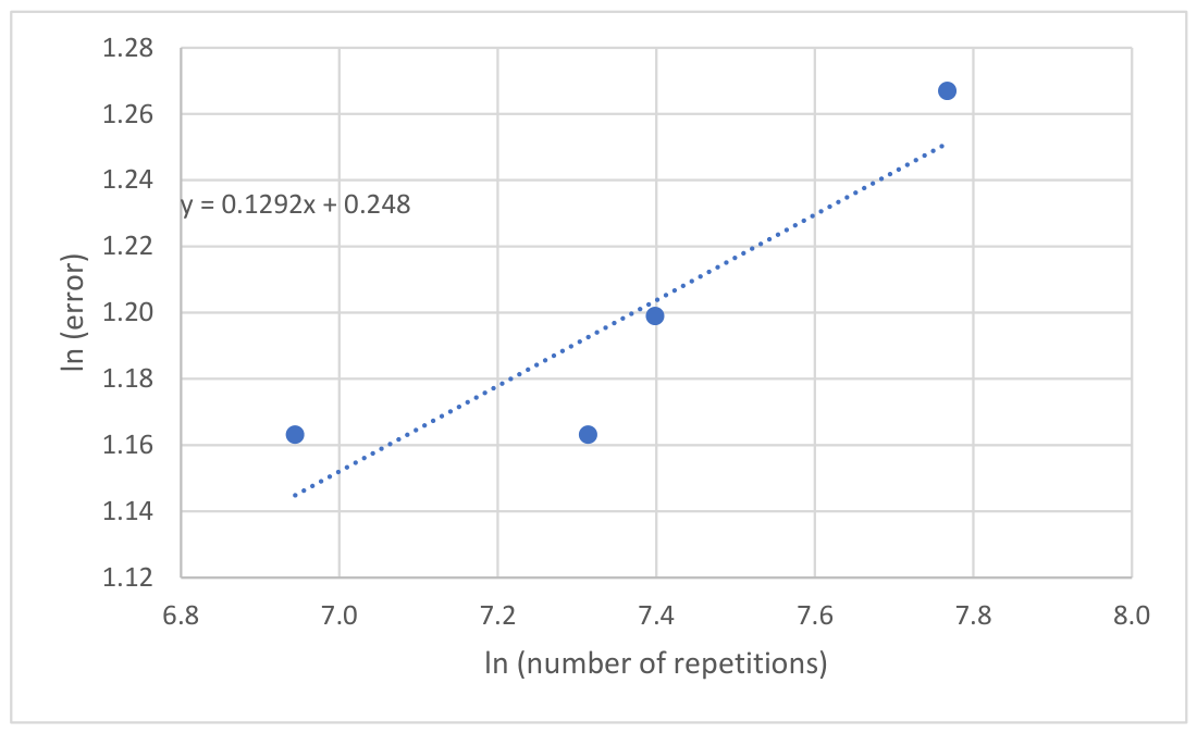
An analogous statistical analysis was performed, similar to that presented in [13] (Figure 3), for the results obtained before and after optimization, following the approach of Naskinova et al. [14,15]. The obtained results shown in Table 1 lead to the linear regression line shown as a graph in Figure 5. The correlation coefficient and the corresponding coefficient of determination indicate a clear trend in the experimental data and support the practical observation of cumulative position drift.
Figure 5.
Relation between ln (number of repetitions) and ln (absolute value difference of theoretical and real angle values).
The estimated slope of the regression model can be used as an indicator for comparing the behavior of different experimental processes:
This type of regression-based representation has been used in modeling practical processes and for comparing trends through the estimated slope. In our case, the exact formulation is:
The proposed solution is presented in the following section. In this approach, the setpoint is generated from the previous theoretical value rather than from the measured feedback.
3.3. Improved Setpoint Generation for Eliminating Cumulative Position Error
To address the cumulative positioning deviation identified in the previous section, an improved strategy for generating successive angular setpoints is proposed. The new approach ensures that each commanded position is derived from the theoretical angular sequence, thereby maintaining strict adherence to the intended indexing pattern.
In this method, each new setpoint is calculated using the relation (2).
where NP—new position setpoint, OP—old position setpoint.
NP = OP + 45.00°,
By basing the setpoint on the previous theoretical value, the commanded positions remain independent of small measurement variations in the encoder feedback. This prevents the accumulation of minor deviations over repeated cycles and ensures consistent angular spacing between successive positions. As the theoretical position remains the same, increased by 45°, the small error remains local to each processing of a rotation step and does not affect the process.
The encoder feedback is still utilized for motion verification and diagnostic purposes by the servo driver internally, such as confirming that the desired position has been reached and detecting potential anomalies (e.g., missed steps or mechanical disturbances). However, it no longer influences the generation of future setpoints and the system no longer stops after a certain period of time.
The proposed setpoint generation strategy effectively eliminates the cumulative positioning error observed in the previous implementation. By deriving each new setpoint from the previous theoretical value, the commanded positions remain strictly aligned with the intended angular sequence and the theoretical values for the angle. This prevents the accumulation of small measurement variations originating from the encoder feedback, ensuring stable and drift-free operation over extended periods.
In addition to eliminating cumulative error, the approach significantly improves long-term positioning accuracy. Experimental observations indicate that the total deviation is limited to approximately 0.1–0.2° after 8 h of work, representing a substantial enhancement in system precision. Such accuracy is particularly important for part feeding systems of this kind, where consistent positioning directly influences the reliability of downstream operations such as the pick-up procedure in this particular setup. Similar system-level considerations for automated handling and positioning modules have been reported in related engineering applications [15].
Furthermore, the proposed strategy enhances system robustness and reliability. While encoder feedback is no longer used to generate subsequent setpoints, it remains integral for motion verification and diagnostic purposes. This allows the system to detect anomalies such as missed steps, mechanical slippage, or unexpected disturbances without introducing cumulative drift into the control process.
Finally, the solution is straightforward to implement within existing control architectures. It requires only modification to the setpoint calculation logic, without the need for additional hardware or complex control algorithms. This simplicity facilitates easy integration into both new and existing systems while delivering significant improvements in positioning performance.
After Equation (2) was implemented in the PLC program, a validation test was performed, and the results are presented in Table 2. After the modification, the angular error at the time of the measurement was 0.04°.
Table 2.
Experimental data after applying Equation (2).
4. Conclusions
This study analyzed the causes of position drift in a stepper motor-driven indexing mechanism used in a part feeding system for cylindrical components. Experimental analysis demonstrated that the gradual deviation between the theoretical and actual angular positions was not due to mechanical inaccuracies or missed steps, but rather to the recursive calculation of successive setpoints based on encoder feedback. The inherent measurement variation of the encoder, although small, accumulated over repeated cycles and resulted in a significant long-term positioning error that eventually disrupted the pick-up process.
To eliminate this issue, an improved setpoint generation strategy was proposed, in which each new position command is derived from the previous theoretical setpoint. This approach prevents the accumulation of measurement noise while still allowing encoder feedback to be used for motion verification and diagnostic purposes. Experimental validation confirmed the effectiveness of the proposed method, with the total positioning deviation reduced to approximately 0.1–0.2° after extended operation, compared to a drift of about 3° observed with the initial approach.
The proposed solution is straightforward to implement within existing PLC-based control architectures and does not require additional hardware or complex algorithms. Its application ensures consistent angular indexing, improved long-term accuracy, and enhanced overall reliability of the part feeding system. These findings contribute to the practical design and optimization of automated feeding and orientation mechanisms in industrial environments.
Future work may focus on integrating automated homing or self-calibration routines, as well as extending the approach to other indexing systems and motion control applications requiring high precision and long-term stability.
Author Contributions
Conceptualization, P.M.; methodology, P.M., K.M. and M.M.; validation, Y.S., K.M., P.M.; data curation, P.M.; writing—original draft preparation, P.M., Y.S. and A.T.; writing—review and editing, P.M., Y.S. and A.T. All authors have read and agreed to the published version of the manuscript.
Funding
The authors would like to thank the European Regional Development Fund within the OP “Research, Innovation and Digitalization Programme for Intelligent Transformation 2021–2027”, Project No BG16RFPR002-1.014-0005 Center of competence “Smart Mechatronics, Eco- and Energy Saving Systems and Technologies”.
Institutional Review Board Statement
Not applicable.
Informed Consent Statement
Not applicable.
Data Availability Statement
No new data were created or analyzed in this study. Data sharing is not applicable to this article.
Conflicts of Interest
The authors declare no conflicts of interest.
Abbreviations
The following abbreviations are used in this manuscript:
| PLC | Programmable logic controller |
| TON | Timer On-Delay |
| HMI | Human Machine Interface |
References
- Nurgizat, Y.; Sultan, A.; Zhetenbayev, N.; Ayazbay, A.; Uzbekbayev, A.; Sergazin, G.; Alipbayev, K. Comparative Analysis of Modern Robotic Demining Complexes and Development of an Automated Mission Planning Algorithm. Eng. Proc. 2025, 104, 63. [Google Scholar] [CrossRef] [Scilit]
- Bednarski, B.; Jackiewicz, K.; Gałecki, A. Influence of Microstepping Signal Shape on Shaft Movement Precision and Torque Variation of the Stepper Motor. Energies 2021, 14, 6107. [Google Scholar] [CrossRef] [Scilit]
- Suh, S.; Kim, W. Position Control Based on Add-on-Type Iterative Learning Control with Nonlinear Controller for Permanent Magnet Stepper Motors. Appl. Sci. 2021, 11, 587. [Google Scholar] [CrossRef] [Scilit]
- Li, C.; Tang, S.; Yin, M.; Zhao, X.; You, H. Enhancing Position Tracking of Hybrid Stepper Motors Using Lyapunov-Based Current Controllers. Electronics 2025, 14, 1997. [Google Scholar] [CrossRef] [Scilit]
- Fazylova, A.; Alipbayev, K.; Aden, A. Automated Control of Dynamic Loads in Drive Systems. Eng. Proc. 2025, 104, 76. [Google Scholar] [CrossRef] [Scilit]
- Xuan, H.; Trong, V. Effective Electromagnetic Models for the Design of Axial Flux Permanent Magnet Generators in Wind Power. Eng. Proc. 2025, 104, 82. [Google Scholar] [CrossRef] [Scilit]
- Dichev, D.; Koev, H.; Diakov, D.; Panchev, N.; Miteva, R.; Nikolova, H. Automated System for Calibrating Instruments Measuring Parameters of Moving Objects. In Proceedings of the 2017 International Symposium ELMAR, Zadar, Croatia, 18–20 September 2017; pp. 219–224. [Google Scholar] [CrossRef] [Scilit]
- Dichev, D.; Kogia, F.; Nikolova, H.; Diakov, D. A Mathematical Model of the Error of Measuring Instruments for Investigating the Dynamic Characteristics. J. Eng. Sci. Technol. Rev. 2018, 11, 14–19. [Google Scholar] [CrossRef] [Scilit]
- Dichev, D.; Zhelezarov, I.; Karadzhov, T.; Madzharov, N.; Diakov, D. Method for Measuring Motion Parameters of Moving Objects. In Proceedings of the 12th International Scientific and Practical Conference, Rezekne, Latvia, 20–22 June 2019; Volume 3, pp. 27–31. [Google Scholar] [CrossRef] [Scilit]
- Raychev, R.; Delova, I.; Borisov, T.; Mirchev, Y. Crack Growth Modeling in CT Specimens: The Influence of Heat Treatment and Loading. Eng. Proc. 2025, 100, 61. [Google Scholar] [CrossRef] [Scilit]
- Delova, I.; Borisov, T.; Mirchev, Y.; Raychev, R. Numerical Modeling and Analysis of Fatigue Failure in 42CrMo4 Steel Pivot Bolts at Different Heat Treatments. Eng. Proc. 2025, 100, 52. [Google Scholar] [CrossRef] [Scilit]
- Hong, Y.; Lee, S.; Li, T. Numerical Method of Pricing Discretely Monitored Barrier Option. J. Comput. Appl. Math. 2015, 278, 149–161. [Google Scholar] [CrossRef] [Scilit]
- Naskinova, I.; Lazarova, M.D.; Todorov, M.; Kolev, M. Advancing Predictive Maintenance Modeling for Renewable Energy Systems. J. Phys. Conf. Ser. 2025, 3145, 012002. [Google Scholar] [CrossRef] [Scilit]
- Naskinova, I.; Stoilova, S.; Kolev, M.; Vasileva, Y. Data-centric Reliability Modeling for Energy Assets. J. Phys. Conf. Ser. 2025, 3145, 012003. [Google Scholar] [CrossRef] [Scilit]
- Panev, P.; Chivarov, N.; Shivarov, S.; Paneva, M. Design of a Loading and Unloading Palletizer Module for Transport Service Robot. In Proceedings of the 26th International Conference on Circuits, Systems, Communications and Computers (CSCC 2022), Chania, Greece, 19–22 July 2022; IEEE: Piscataway, NJ, USA, 2022; pp. 296–299. [Google Scholar] [CrossRef] [Scilit]

Disclaimer/Publisher’s Note: The statements, opinions and data contained in all publications are solely those of the individual author(s) and contributor(s) and not of MDPI and/or the editor(s). MDPI and/or the editor(s) disclaim responsibility for any injury to people or property resulting from any ideas, methods, instructions or products referred to in the content. |
© 2026 by the authors. Licensee MDPI, Basel, Switzerland. This article is an open access article distributed under the terms and conditions of the Creative Commons Attribution (CC BY) license.