


Abstract
Lightning strikes with large current amplitudes and a steep current wave front in cases of multiple lightning strikes can cause significant overvoltages. The number of overvoltage impulses depends significantly on the lightning parameters, the overhead line parameters and the tower grounding impedance. While the probability for back flashovers from towers to phase conductors (power line trips) depends on lightning current amplitude, impulse steepness and tower grounding resistance, the magnitudes of overvoltages reaching the nearby substation, Ground Potential Rise (GPR) and step and touch voltage distribution profiles depend exclusively on substation grounding impedance. In order to study and take into account such a large number of parameters influencing the probability for overvoltages to occur, several models in the ATP simulation program (v. 7.6) have been implemented. This allows us to study the influence of tower and substation grounding impedances on the magnitude and the form of atmospheric overvoltages and their impact on the safety of personnel in the substation area in cases of direct lightning strikes on nearby power line towers or lightning protection cables. A differentiation has been made between grounding resistance and grounding impulse impedance as a prerequisite for more accurate modeling and more precise calculations.
1. Introduction
Atmospheric overvoltage magnitudes in high-voltage overhead power lines, especially those caused as a result of back flashovers through towers, are purely dependent on grounding impedance. Since lightning surges are associated with high frequencies that are typically in the range between hundreds of kHz and a couple of MHz, grounding impedances of towers and substation grounding is highly dependent on the grounding electrode system’s inductance, capacitance and soil ionization processes [1].
Some old sources claim that grounding impedance (impulse impedance) decreases significantly compared to grounding resistance at industrial frequency, dependent on soil resistivity, due to intensive ionization processes in high-soil-resistivity regions [2]. Burgsdorf, in his research about grounding grid design [3], claims that impulse grounding impedance may be lower than industrial frequency grounding resistance for small-configuration grounding electrode systems and significantly higher for large, complex grounding installations (e.g., in substations). In recent studies it has been proven that using grounding resistance rather than grounding impedance for the calculation of atmospheric overvoltages can result in errors reaching up to +25% and grounding electrodes under dimensioning [4]. Tower back flashovers are typical for overhead distribution and transmission lines where insulation levels are less or comparable with the atmospheric overvoltage magnitudes. In such cases, overvoltage magnitudes are highly dependent and decrease significantly with lower tower grounding impedances [5]. The influence of grounding impedance modeling, i.e., taking into account grounding electrodes’ inductance, mutual inductance, capacitance and soil ionization phenomena, is critical for correct software modeling and the calculation of atmospheric overvoltages in overhead electrical power lines [6,7].
Often, overvoltages are transferred from high-voltage to low-voltage electrical power distribution systems, causing problems with the electromagnetic compatibility of sensitive electronic and telecommunication equipment [8].
This paper is intended to clarify the influence of tower and substation grounding impedances in the calculation of atmospheric overvoltages in overhead 110 kV electrical power lines in cases of back flashovers by means of ATP software v. 7.6 modeling.
2. Probabilistic Characteristics of Atmospheric Overvoltage Parameters in 110 kV Overhead Electrical Power Lines
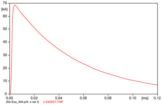
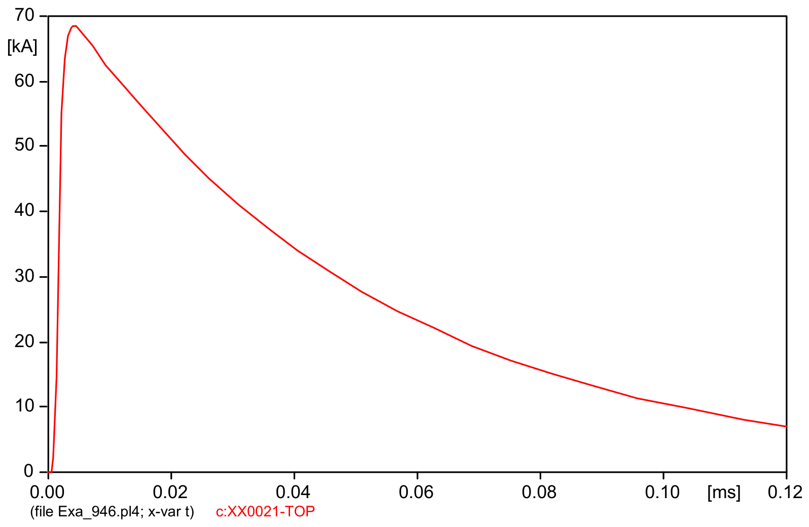
During thunderstorms, multiple lightning strikes can occur. The probability that a single lightning strike will become multiple strikes is 0.55. The typical current waveform during multiple negative lightning strikes is illustrated in Figure 1. In multiple negative lightning strikes, the current amplitude of the first strike is higher than that of subsequent strikes. Subsequent strikes have smaller current amplitudes but steeper current fronts. Atmospheric overvoltages on 110 kV power lines occur because of a direct lightning strike on a phase conductor, a lightning strike on the tower or on the lightning protection cables, followed by a back flashover to the phase conductors. When the influence of grounding impedance for the calculation of atmospheric overvoltages in a HV(110 kV)/MV substation is taken into account, only cases of back flashover are taken into consideration.
Figure 1.
Form of lightning current in the time domain.
The probability for exceeding the current amplitude of the first lightning strike is represented by Erickson–Anderson’s formula [8]:
The average value of the lightning current in (1) has a magnitude of 35.4 kA. The lightning currents used in the simulation have amplitudes of 70 and 35 kA and have the shape presented in Figure 1.
The following expression is used to calculate the probability that the next lightning strike will exceed the lightning current amplitude [8]:
The probability distribution for subsequent lightning strikes is similar to that for the first strike, but the same probability corresponds to smaller currents. The average lightning current, according to (2), is 11.47 kA. The probability of exceeding the lightning current’s steepness A is [9]:
The mathematical law that governs the distribution between the amplitude and steepness of the lightning current is then [8]:
In the case of lightning strikes on the lightning protection cable of a 110 kV power line, the probability for back flashover increases, because air breakdown voltage between the tower and the phase conductor is comparable with the impulse insulation level of the power line (550–650 kV). The lightning current at which back flashover can occur can be determined using the following expression [9]:
where the designations have the following meanings:
- —grounding tower impedance;
- —coefficient indicating the part of the lightning current passing through the tower ( for a tower with a lightning protection cable);
- —coefficient indicating the coupling between the phase conductor and the lightning protection cable ();
- —positive impulse breakdown voltage with 50% probability;
- h—average height of the phase conductor;
- M—mutual inductance between the conductors and the main lightning channel.
Equation (5) illustrates the influence of tower grounding impedance on the magnitude of the lightning current that would cause a back flashover. Expression (5) is also valid for the end tower adjacent to the substation.
For a 110 kV overhead power line, direct lightning strikes on the tower and subsequent back flashovers are of great importance in determining the number of power line trips. The average annual number of trips (trip rate) due to lightning strikes on towers in the high-voltage power network is [10,11]:
where is the probability of exceeding the lightning current at which back flashover can occur, calculated according to (5); and is the number of lightning strikes on the tower or on the lightning protection cables in proximity to the tower.
where is the lightning range and is the number of hours with lightning activity per year.
3. Modeling of a High-Voltage Substation in ATP Software in the Case of a Lightning Strike on an AC Line Tower in Proximity to the Substation: Simulation Results
The number of back flashovers depends significantly on the impulse breakdown voltage of the insulator; on the lightning current parameters, steepness and amplitude; on the line parameters; and on the tower grounding impedance.
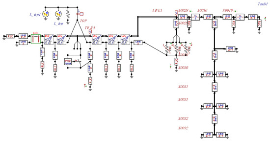
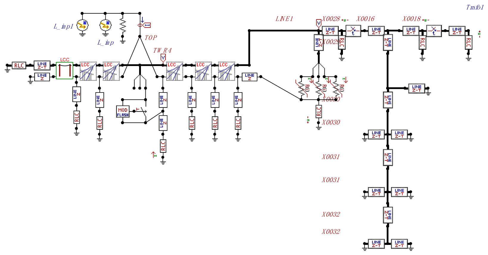
In order to take into account such a large number of parameters influencing the probability that back flashover will occur, a HV AC electrical power substation was modeled in the specialized software product ATP, as presented in Figure 2 [12].
Figure 2.
Model of a HV/MV AC substation for studying atmospheric overvoltages when a power line tower is struck near the substation.
3.1. ATP Model Assumptions, Simplifications and Limitations
Overhead power lines are modeled using their wave impedance, which is calculated as follows:
where r is the radius of the tower, and h is the height of the tower.
The software model has the following assumptions, simplifications and limitations:
- The frequency-dependent linear JMarti model was used in ATP to model the 110 kV power line for the last five inter-spans. The model very accurately reproduces the coupling behavior in multitower systems [13]. The JMarti model provides an accurate numerical basis for calculating line impulses. To transfer the method to a system of interconnected power lines, the “Modal Component Method” is used. This method can be solved numerically at only one frequency. To reduce the resulting error, the linear JMarti model calculates an average frequency at which the transformation is performed from the key data of the frequency range and a set frequency. For a high-frequency impulse, typical for lightning surges, the resulting error is very small. In this high-frequency range, the transformations for different frequencies differ very little from each other. Each linear distance before the tower being struck by lightning is modeled by the JMarti model.
- Generally, five transmission lines’ spans are modeled by the JMarti model and the lightning strike is assumed and modeled to occur at the top of the tower or on the lightning protection cable, three transmission lines’ span before the substation.
- The beginning of the power line is modeled with two sections connected in series, the first with a length of 30 km modeled by its length, active resistance and its positive and zero-sequence wave characteristics, and the second section with a length of 3.2 km, modeled again with the JMarti frequency-dependent linear model.
- Power line towers are represented with their height, active resistance, surge wave propagation velocity, and wave impedance.
- Substation bus bars are modeled with their length, active resistance and their positive and zero-sequence parameters—wave impedances and ; and wave propagation velocities and .
- The power transformer is represented with its capacitance.
- Voltage-measuring transformers are represented by their capacitances.
- Surge arresters are modeled with their volt–ampere characteristics.
- The grounded lightning protection cable of the transmission power lines ends at the substation entrance and is effectively grounded there.
- The grounding of towers is modeled by impedances . If soil resistivity is high (e.g., 3000 Ω ·m and more), then the permissible value of the grounding impedance is 30 Ω.
- The grounding of the substation is modeled as an equipotential surface with an impedance .
With an increase in the frequency spectrum of the lightning current, the grounding impedance of the towers also increases. In the presence of long grounding electrodes in the substation, due to the lower propagation speed of electromagnetic disturbances in the soil, the effective grounding area for steep lightning fronts decreases, which also leads to an increase in the grounding impedance, compared to its active component [14].
If the overvoltage between the tower and the conductor is greater than the impulse insulation breakdown voltage with positive polarity (depending on the air distance and the time for insulation breakdown), then a back flashover occurs through the nearest insulator related to the tower.
3.2. Simulation Results and Discussion
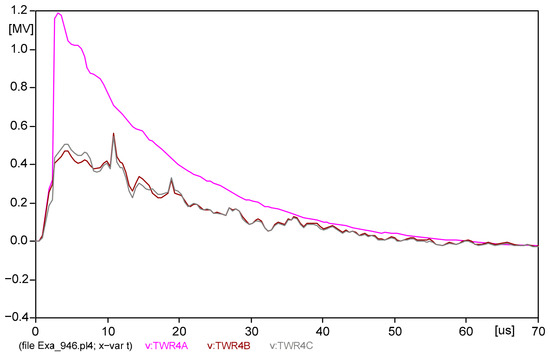
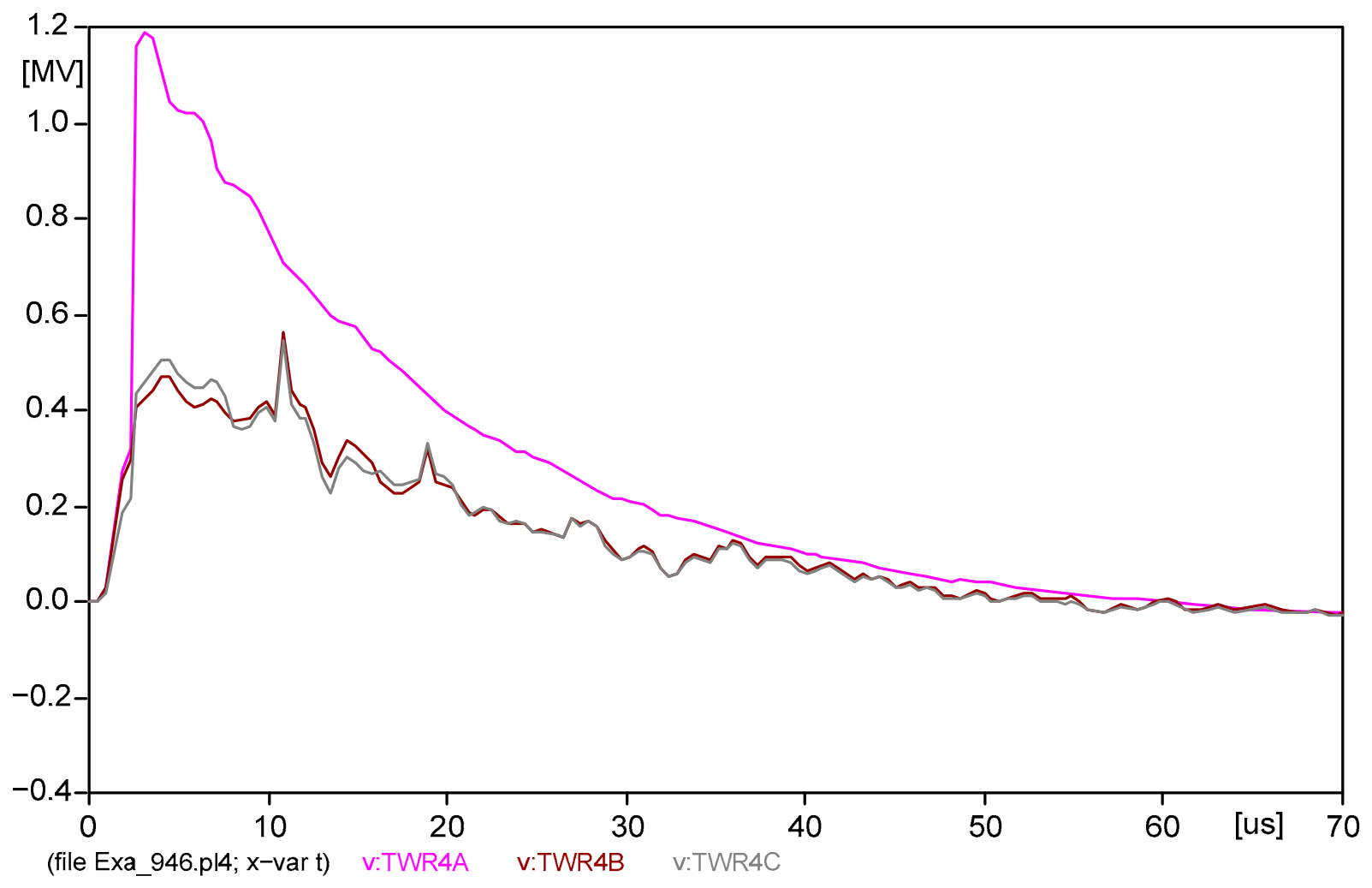
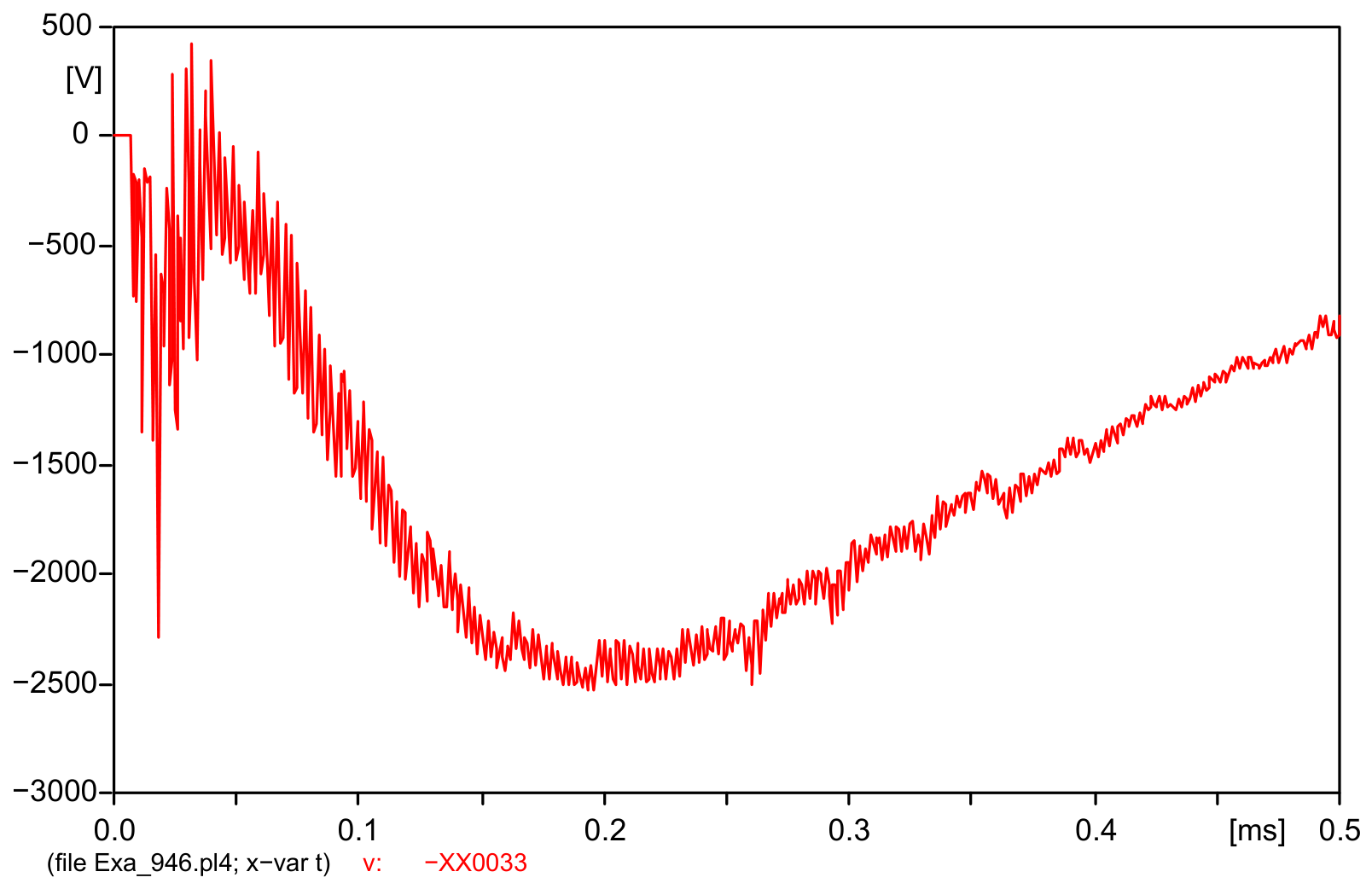
A couple of simulations were performed with the setup already described. The 110 kV power line leaving the substation is modeled with its wave impedance and its length. The voltages in the phase conductors at the lightning impact location in the time domain are shown in Figure 3.
Figure 3.
Distribution of overvoltages on the phase conductors of the power line during a lightning strike with a current of 70 kA.
After the surge arresters at the substation have activated, the voltages supplying the power transformer drop to the permissible values.
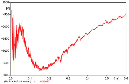
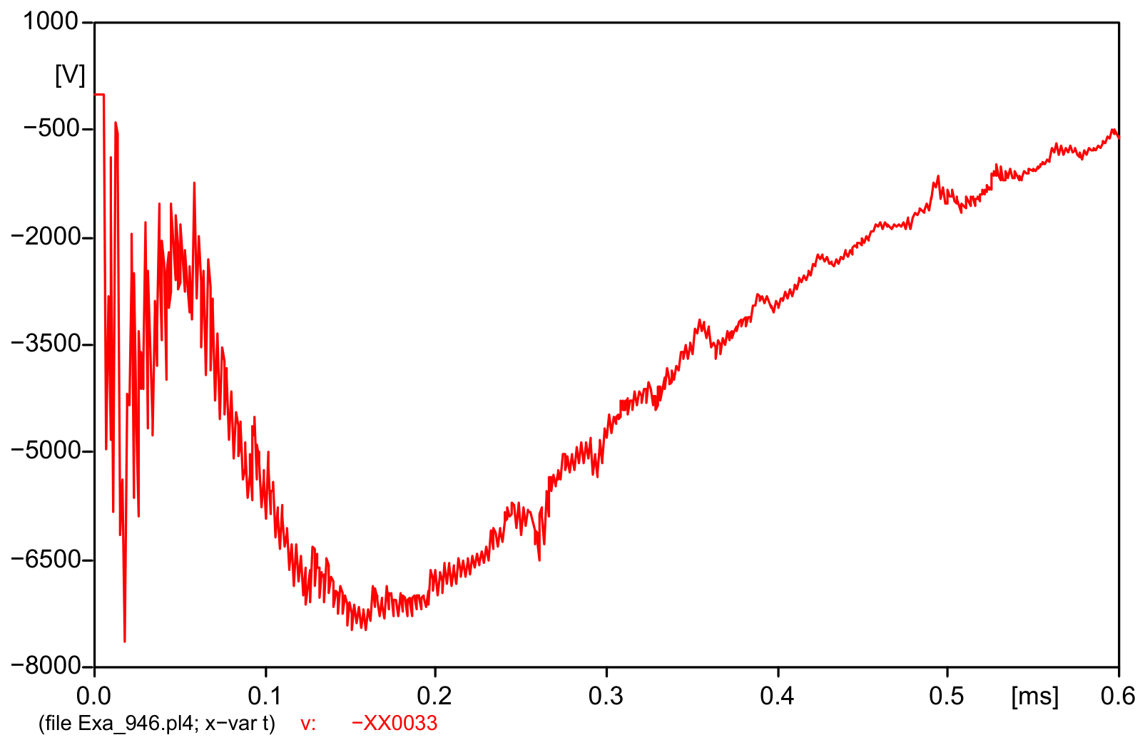
When modeling the substation grounding system as lumped impedance with a value of 5 Ω, the following graphical profile (Figure 4) is obtained for the Ground Potential Rise (GPR) in the time domain, which is indicative of the distribution of touch and step voltages in the area of the substation in the event of a lightning strike on the lightning protection cable near the substation (for three inter-tower spans).
Figure 4.
GPR in the substation grounding system if the substation grounding impedance is 5 Ω and the lightning current amplitude is 70 kA.
GPR in fact is equal to the transient voltage drop over the lumped grounding impedance of the system.
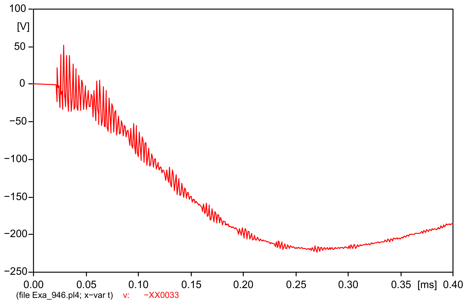
Figure 5 shows the transient voltage drop over the grounding grid with a lumped grounding impedance of 2.5 Ω which corresponds to the Ground Potential Rise (GPR) in the case of a lightning strike on the lightning protection cable or the nearest powerline tower. Compared to the case from Figure 4, GPR and touch and step voltages will be significantly lower.
Figure 5.
GPR in the substation grounding system if the substation grounding impedance is 2.5 Ω and the lightning current amplitude is 70 kA.
When modeling the substation grounding electrode system as lumped impedance with a value of 0.5 Ω, the distribution of GPR in the time domain is presented in Figure 6 and has the lowest values. The expected profiles of touch and step voltages will be within the safety margins. This is a reason why, in most of the international standards, the permissible grounding resistance limit for the grounding electrode systems of substations and power plants is 0.5 Ω.
Figure 6.
GPR in the substation grounding system if the substation grounding impedance is 0.5 Ω and the lightning current amplitude is 70 kA.
Table 1 summarizes the results from ATP simulations for the maximum GPR that is obtained over the grounding electrode system as a function of the lightning current amplitude of the first strike , the lightning current amplitude of the second strike , the grounding impedance of the towers and the grounding impedance of the substation grounding electrode system .
Table 1.
Maximum GPR over the grounding electrode system depending on lightning current amplitude, and grounding impedances of the towers and the substation grounding electrode system.
From the simulation results in Table 1 it is obvious that tower grounding impedance affects the magnitude of the lightning current at which back flashover occurs. Increases in tower grounding impedance would no doubt result in an increase in the trip rate in 110 kV power lines as a result of back flashovers.
On the other hand, substations’ grounding grid impedance affects the magnitudes of GPR distribution in the time domain and therefore the touch and step voltage profiles in the substation, directly affecting personnel safety and insulation coordination.
For a lightning current amplitude IM1 = 70 kA and substation grounding impedance = 5 Ω, GPR is 7286 V, which significantly exceeds the maximum allowable value of 5000 V.
For lightning current amplitudes IM1 = 70 and 35 kA, and substation grounding impedance = 5, 2.5 Ω results in GPR below the threshold of 5000 V, but the obtained values between 1200 and 3930 V may result in substantial safety risk for personnel in relation to inadmissible step and touch potentials.
Regardless of the lightning current amplitude, substation grounding impedance below 0.5 Ω is considered safe in regard to step and touch voltage hazards.
Instead of grounding impedance, in many regulatory documents (incl. in Bulgaria) standards prescribe a maximum allowable substation grounding resistance of 0.5 Ω, which can result in under-dimensioning of substation grounding installations by up to 2.5 %. This is especially valid in cases of direct lightning strikes and lightning strikes to towers and earth protection cables and consequent back flashovers, which also result in increases in touch and step voltage profiles over the safe limits.
Some 110 kV electrical power substations in the Bulgarian Power System are operated with an isolated neutral on the HV side (110 kV) of the transformers, which normatively allows a higher permissible value for the substation grounding resistance, especially in regions with high values of soil resistivity. The power transformer’s star point in such cases is protected against overvoltages by surge arrestors, selected properly. The higher grounding resistance (impedance) in such cases leads to significantly increased step and touch voltages in the substation, not only in cases of lightning strikes but also in cases of single-phase short-circuits.
4. Conclusions
Higher values of the grounding impedance, both for power line towers and especially for substation grounding electrode systems, result in increased and dangerous Ground Potential Rise in the substation. Since GPR is proportional to step and touch voltage magnitudes in the substation area, such mitigation in grounding impedance values also results in increased risk for operational personnel from electrocution in cases of intensive lightning activity and single-phase short-circuits.
Higher grounding impedances in line towers near the substation reduce the magnitude of the lightning current through the earth, at which point back flashovers occur, and therefore the probability of increasing the trip rate of such power lines increases too. In cases with multiple lightning strikes, the second and subsequent lightning strikes do not lead to an additional increase in overvoltages nor the touch and step-voltage magnitudes in the substation.
In addition, the increased current wave steepness for the second and subsequent lightning strikes does not lead to higher values for GPR in the substation and is not a cause for safety hazards in regard to step and touch voltages.
Keeping substation grounding impedance below 0.5 Ω, even in cases with an insulated neutral in the power transformer, is a prerequisite for safer technical operation, better electromagnetic compatibility and increased reliability of power equipment—not only in terms of atmospheric overvoltages but also in terms of high-current insulation faults to the earth.
Author Contributions
Conceptualization, K.I. and G.V.; methodology, K.I. and G.V.; software, K.I. and I.L.; validation, K.I. and I.L.; formal analysis, K.I., G.V. and I.L.; investigation, K.I., G.V. and I.L.; resources, K.I. and G.V.; data curation, G.V. and I.L.; writing—original draft preparation, K.I. and G.V.; writing—review and editing, G.V. and I.L. All authors have read and agreed to the published version of the manuscript.
Funding
This research received no external funding.
Institutional Review Board Statement
Not applicable.
Informed Consent Statement
Not applicable.
Data Availability Statement
The original contributions presented in this study are included in the article. Further inquiries can be directed to the corresponding author.
Conflicts of Interest
The authors declare no conflicts of interest.
Abbreviations
The following abbreviations are used in this manuscript:
| GPR | Ground Potential Rise |
| HV | High voltage |
| AC | Alternating current |
| MV | Medium voltage |
References
- Clark, D.; Mousa, S.; Harid, N.; Griffiths, H.; Haddad, A. Lightning Current Performance of Conventional and Enhanced Rod Ground Electrodes. IEEE Trans. Electromagn. Compat. 2021, 63, 1179–1188. [Google Scholar] [CrossRef] [Scilit]
- Venkov, G.; Petrov, P. Technical Safety Engineering, 1st ed.; Gabrovo Print LTD: Gabrovo, Bulgaria, 2002; pp. 167–168. [Google Scholar]
- Burgsdorf, V.V.; Yakobs, A.I. Grounding Installations in Electrical Power Systems, 1st ed.; Energoatmizdat: Moscow, Russia, 1987; pp. 294–300. [Google Scholar]
- Mestriner, D.; Ribeiro de Moura, R.A.; Procopio, R.; de Oliveira Schroeder, M.A. Impact of Grounding Modeling on Lightning-Induced Voltages Evaluation in Distribution Lines. Appl. Sci. 2021, 11, 2931. [Google Scholar] [CrossRef] [Scilit]
- Yokoyama, S. Lightning Performance of Grounding of Overhead Power Distribution Lines. IEEJ Trans. Power Energy 2014, 134, 91–94. [Google Scholar] [CrossRef] [Scilit]
- Wu, J.; He, J.; Zhang, B.; Zeng, R. Influence of grounding impedance model on lightning protection analysis of transmission system. Electr. Power Syst. Res. 2016, 139, 133–138. [Google Scholar] [CrossRef] [Scilit]
- Carvalho, K.A.; Silveira, F.H. Evaluation of the lightning performance of grounding electrodes using FDTD-based computational model: Influence of absorbing boundary conditions and representation of the frequency-dependence of soil parameters. Electr. Power Syst. Res. 2022, 213, 108728. [Google Scholar] [CrossRef] [Scilit]
- Stoykov, I.; Mihaylov, G.; Hristova, T.; Stoyanov, I. Study of Power Supplies Used in Telecommunication Systems. In Proceedings of the 10th International Conference on Energy Efficiency and Agricultural Engineering (EE&AE), Stara Zagora, Bulgaria, 5–7 November 2025; pp. 1–5. [Google Scholar] [CrossRef] [Scilit]
- Genov, L. High Voltage Engineering in the Electrical Power Systems; Technica: Sofia, Bulgaria, 1979. [Google Scholar]
- Tihodeev, N.N. Leitfaden für Schutz von inneren und außeren Überspannungen in den elektrischen Netzen 3–750 kV; Energija: Leningrad, Russia, 1975. [Google Scholar]
- Eriksson, A.J.; Weck, K.H. Simplified Procedures for Determining Representative Substation Impinging Lightning Over-voltages. In Proceedings of the CIGRE 1988 Session, Paris, France, 28 August–3 September 1988. [Google Scholar]
- Prikler, L. Lightning Performance and Switching Overvoltage Studies of an Uprated Transmission Line. EEUG News, 9–11 November 1998; pp. 10–23.
- Hoidalen, H.K. ATPDraw Version 7.x for Windows: User’s Manual; Norwegian University of Science and Technology (NTNU): Trondheim, Norway, 2024. [Google Scholar]
- Selivanov, V.N.; Danilin, A.N.; Kuklin, D.V.; Kosorukov, A.V. Investigation of Grounding Resistance of Transmission Line Towers and Substation Equipment in the Microsecond Time Range under Conditions of High Soil Resistivity. In Proceedings of the Second Russian Conference on Lightning Protection, Moscow, Russia, 22–24 September 2010. [Google Scholar]

Disclaimer/Publisher’s Note: The statements, opinions and data contained in all publications are solely those of the individual author(s) and contributor(s) and not of MDPI and/or the editor(s). MDPI and/or the editor(s) disclaim responsibility for any injury to people or property resulting from any ideas, methods, instructions or products referred to in the content. |
© 2026 by the authors. Licensee MDPI, Basel, Switzerland. This article is an open access article distributed under the terms and conditions of the Creative Commons Attribution (CC BY) license.