


Abstract
Grid-following inverters play a vital role in integrating renewable energy systems into modern power grids. However, their performance deteriorates under grid voltage unbalance and uncertain grid impedance, resulting in current distortion and double-frequency active-power oscillations. This paper proposes a robust dual-sequence current control strategy for a three-phase grid-following inverter operating under these adverse conditions. The inverter model explicitly incorporates grid impedance uncertainty and is represented using a polytopic uncertainty model. Positive- and negative-sequence current controllers are independently designed based on a state-feedback integral structure, where the control gains are synthesized using linear matrix inequality (LMI) optimization to guarantee robust stability over the entire uncertainty range. In addition, sequence-based reference-current generation is employed to suppress the negative-sequence current and eliminate double-frequency power oscillations under unbalanced grid voltages. The effectiveness of the proposed approach is evaluated through simulation studies and compared with a previous robust power controller. The results suggest that the proposed controller significantly suppresses the 120 Hz active-power oscillation despite the presence of grid voltage unbalance and impedance uncertainty. Compared with a previous controller, the magnitude of the 120 Hz component is reduced by approximately 91%, demonstrating improved power-quality performance under grid voltage unbalance and impedance uncertainty.
1. Introduction
With the fast growth in the utilization of renewable energy resources, there has been a greater inclination toward the use of grid-following inverters as the means of interfacing the renewable generation systems with the grid [1]. The task of matching the renewable energy source with the grid and controlling the flow of both active and reactive power according to the needs of the grid lies with these converters. This has made it vital to ensure high-quality power with effective control over the current [2].
In practical power distribution systems, the operation of grid-following inverters is not always optimal [3]. The presence of voltage imbalance in the grid due to unequal loads, single-line faults, and unequal impedance of feeders results in the generation of negative-sequence voltage components, causing a doubling of frequency oscillation in the current and power in the inverter [4]. This results in a reduction in power quality, higher harmonic distortion, and decreased efficiency and stability of the whole system. To counter this problem, various control methods have been developed, including proportional-integral (PI) control [5,6], deadbeat current control [7,8,9], model predictive control [10,11,12], direct power control [13,14,15], and state-feedback-based controllers [16,17,18]. Although these methods can provide effective current or power regulation under unbalanced grid conditions, their performance may be affected by parameter variations and uncertain grid impedance. Robust LMI-based control has been investigated to explicitly consider impedance uncertainty. In particular, our previous work [19] developed an LMI-based robust state-feedback integral controller considering uncertainties in the filter and grid impedance. However, ref. [19] did not explicitly employ independent positive- and negative-sequence current control for grid voltage unbalance. Therefore, the double-frequency power oscillation caused by the interaction between positive- and negative-sequence components remains insufficiently addressed.
Another issue, which has drawn increasing research interest in recent years, is the uncertainty in the grid impedance. Unlike inverter-side filter parameter values, the equivalent impedance of the grid keeps varying with the change in grid topology, feeder arrangement, transmission line switching, loading, and faults. These impedance variations affect the dynamics seen by the inverter and may lead to reduced tracking precision, distorted currents, diminished stability margins, and power oscillations. As the grid impedance is rarely known during operation, controllers based on nominal impedance values may not perform well over a wide range of operations.
A number of research efforts have looked into the development of robust control systems that can deal with parameter uncertainties using optimization techniques like linear matrix inequalities (LMIs). Similarly, sequence-based current controllers have been successful in overcoming the detrimental impacts of voltage unbalance by controlling positive- and negative-sequence currents separately. However, these two lines of research have not yet been pursued together. The most popular techniques dealing with the problem of voltage unbalance assume a constant value for the grid impedance, whereas those considering uncertainty in impedance have been developed for the case of balanced grids.
In this regard, this work proposes a robust dual-sequence current control scheme for a grid-following inverter operating under the combined effects of grid voltage unbalance and impedance uncertainty. Positive- and negative-sequence currents are controlled separately, while the control gains are designed using LMI optimization considering the uncertain grid impedance. In addition, sequence-based reference-current generation is employed to suppress the double-frequency active-power oscillation and improve current quality. Compared with [19], the main contribution of this work is the integration of robust impedance uncertainty control with dual-sequence current regulation, enabling simultaneous robust current control and suppression of double-frequency power oscillations under grid voltage unbalance.
2. Dynamic Modeling of the Grid-Following Inverter
2.1. Three-Phase L-Filtered Inverter Dynamic Model
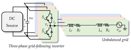
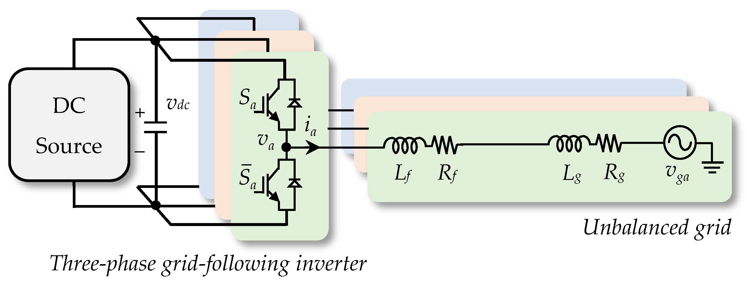
Figure 1 illustrates the three-phase grid-following inverter connected to the utility grid through an L-filter. In practical distribution systems, the equivalent grid impedance is generally unknown and varies with network operating conditions. Therefore, the grid impedance is explicitly incorporated into the mathematical model to improve the robustness of the proposed controller. Under Kirchhoff’s voltage law, the phase-domain dynamics are expressed as
where represent the equivalent grid inductance and resistance, are the filter inductance and resistance, are the filter currents, are the inverter output voltages, and denote the grid voltages.
Figure 1.
Grid-following inverter considering grid impedance.
Unlike conventional inverter models that assume a fixed grid impedance, the proposed model considers the variation in the grid impedance caused by transmission line switching, load changes, and network disturbances. Consequently, the total inductance and resistance observed by the inverter become
Applying the Park transformation to (1) yields the inverter dynamics in the synchronous reference frame:
where , , , , and .
In the current study, an L-filtered inverter was examined in order to keep the system model simple and analyze the coupled influence of the unbalanced voltage of the grid and the impedance uncertainty of the grid. In the case of LCL-filtered inverters, the control scheme proposed in this study can be adapted by adding the dynamics of the capacitor voltage and grid-side currents into the state space representation. This would require the modification of the LMI-based gain synthesis approach to incorporate the additional resonance dynamics along with their respective uncertainties. Nevertheless, explicit damping of LCL resonances is not covered in this paper.
2.2. Positive- and Negative-Sequence Representation
The positive-sequence components will be found under balance operating conditions in the synchronous reference frame. But the presence of the grid voltage imbalance will produce negative-sequence components rotating in the opposite direction, hence leading to second-order oscillations in the current and power output of the inverter. For independent regulation of both components, the dq components will be split up into positive- and negative-sequence components.
The resulting dynamic equations become
where and .
The opposite signs of the cross-coupling terms reflect the opposite rotational direction of the negative-sequence components.
2.3. Discrete-Time Model
Since the proposed controller is implemented on a digital processor, the continuous-time dynamics in (5) are transformed into discrete-time models using the forward Euler approximation with a sampling period Ts. The discrete-time representation of the positive- and negative-sequence current dynamics can therefore be written as
where , , , , , and I denotes the 2 × 2 identity matrix.
The discrete-time model is used as the starting point for developing the optimal controller since this model is easily implementable in the digital domain and enables formulation of the LMI optimization problem.
2.4. Grid Impedance Uncertainty Model
As the equivalent impedance of the grid is not known in advance in real-life power distribution systems, it changes continuously due to changes in feeder configuration, transmission line switching, distributed generation penetration, and operating conditions of the loads. In addition, the parameters of the filter at the inverter side are not exactly equal to their nominal values due to tolerances of components and temperature. The total inductance and resistance in (2) the uncertain parameters are assumed to satisfy
Alternatively, the uncertainty ranges can be represented using an uncertainty coefficient ρ > 1:
Considering the upper and lower bounds of the four uncertain parameters, sixteen vertex systems are obtained. The discrete-time system matrices corresponding to each vertex are denoted by
Consequently, the uncertain inverter model is represented by the convex polytope [20]:
where denotes the convex weighting coefficient associated with each vertex system.
The controller developed in the following section is designed to satisfy the stability conditions for all vertex systems in Ω, thereby guaranteeing robust current regulation under simultaneous grid voltage unbalance and grid impedance uncertainty.
3. Robust Dual-Sequence Current Control Considering Grid Impedance Uncertainty
The objective of the proposed controller is to simultaneously compensate for the negative-sequence current caused by grid voltage unbalance while maintaining robust current regulation in the presence of uncertain grid impedance. To accomplish this objective, two independent current controllers are designed for the positive- and negative-sequence components. Each controller employs a state-feedback integral structure whose gains are determined using an LMI-based optimization framework [21,22]. The positive- and negative-sequence reference currents and are obtained from the reference-current generation procedure presented in Section 3.3.
The positive-sequence controller is defined as
where is the positive-sequence state-feedback gain, is the integral gain, and denotes the integral state.
Similarly, the negative-sequence controller is expressed as
The positive- and negative-sequence controllers have identical structures but operate independently, allowing the inverter to regulate each sequence without mutual interference. Consequently, the positive sequence is responsible for active-power transfer, whereas the negative sequence suppresses the current imbalance caused by asymmetric grid voltages.
3.1. Augmented System
To facilitate the robust controller synthesis, the state variables are augmented with the integral components. Since the derivation of both controllers is identical, the superscripts p and n are omitted for simplicity.
The augmented state vector is defined as
Using (6) together with the integral equation, the augmented dynamics become
where , , and .
The control law is rewritten in compact form as
Assuming the reference input remains constant during controller synthesis, the augmented closed-loop dynamics become
To guarantee robust stability under all admissible uncertainty realizations, the controller gain is determined using Lyapunov stability theory.
3.2. LMI-Based Controller Synthesis
Consider the quadratic Lyapunov function [23,24]:
The closed-loop system is asymptotically stable if
where denotes the desired convergence rate parameter. In the controller synthesis, is selected as a constant design parameter and is kept fixed for all 16 vertex systems.
Applying the Schur complement yields the following LMI [25,26]:
where , .
Since the inverter model belongs to the uncertainty polytope , the stability condition must be satisfied at every vertex. Therefore,
The controller gain is obtained by solving
Finally,
is used to compute both positive-sequence gain and negative-sequence .
The optimal gains are obtained offline using the YALMIP (R20181012) toolbox in MATLAB (2021b) and subsequently implemented in the digital controller [27].
3.3. Reference-Current Generation for Power-Quality Enhancement
The coupling effect of the positive- and negative-sequence components of the voltage and current results in the formation of power oscillations at double the frequency of the fundamental frequency under unbalanced grid voltage. The double-frequency power oscillations lead to poor power quality due to distortion in the currents and also result in the formation of power ripple along with reduced efficiency of the inverter.
According to the instantaneous power theory, the relationship between the sequence voltages and currents can be expressed as
where denotes the average active power, is the average reactive power, and and represent the cosine and sine components of the double-frequency active-power oscillation, respectively.
To improve the output power quality, the reference-current vector is designed to satisfy , , and . Accordingly, the desired power vector becomes . Solving (22) for the current vector yields
The positive-sequence grid voltage components and and negative-sequence grid voltage components and are obtained from the positive-sequence decomposition of the measured three-phase grid voltage in (4) and are expressed in the synchronous reference frame introduced in (3). Expanding the inverse matrix gives
where .
The positive- and negative-sequence reference currents obtained from (24) are then applied to the corresponding robust sequence controllers in (10) and (11). Therefore, it can be said that the proposed control method controls the desired active power, reduces negative-sequence current, dampens double-frequency power oscillation, and improves the power quality of the grid-following inverter even with uncertain grid impedance.
4. Results and Discussion
The performance of the robust dual-sequence current control scheme suggested in this paper is simulated under the condition of voltage unbalance of the grid and uncertain impedance of the grid. To show the ability of the robust dual-sequence current control scheme in improving the quality of current, power oscillation suppression, and robustness, the robust dual-sequence current control scheme is compared with the traditional dual-sequence current control scheme. The simulation parameters of both controllers are the same. The parameters of the proposed grid-following inverter used in the simulations are summarized in Table 1.
Table 1.
Parameters of the proposed grid-following inverter.
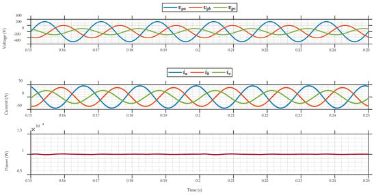
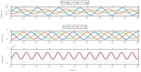
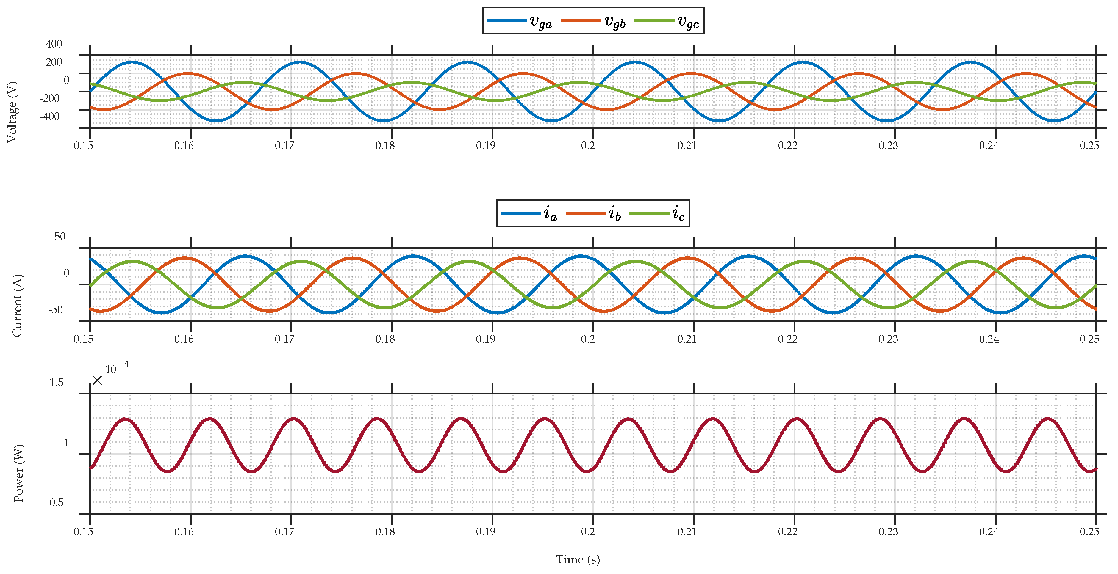
Figure 2 shows that the proposed controller keeps the active power around its 10 kW reference, except for its small 120 Hz oscillating component, whereas the three-phase currents of the inverter are balanced despite the presence of strongly unbalanced voltages on the grid side. On the other hand, Figure 3 shows that the controller in [19] generates an active-power oscillation in the same scenario. This superiority is because of the regulation of positive- and negative-sequence currents independently in the proposed scheme as well as the sequence-based generation of the reference current.
Figure 2.
Steady-state responses of the proposed controller under grid voltage unbalance. From top to bottom: three-phase grid voltages, inverter output currents, and active-power response.
Figure 3.
Steady-state responses of the controller proposed in [19] under grid voltage unbalance. From top to bottom: three-phase grid voltages, inverter output currents, and active-power response.
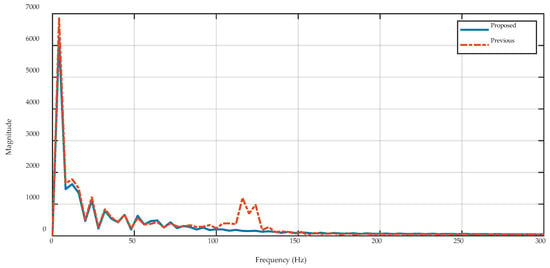
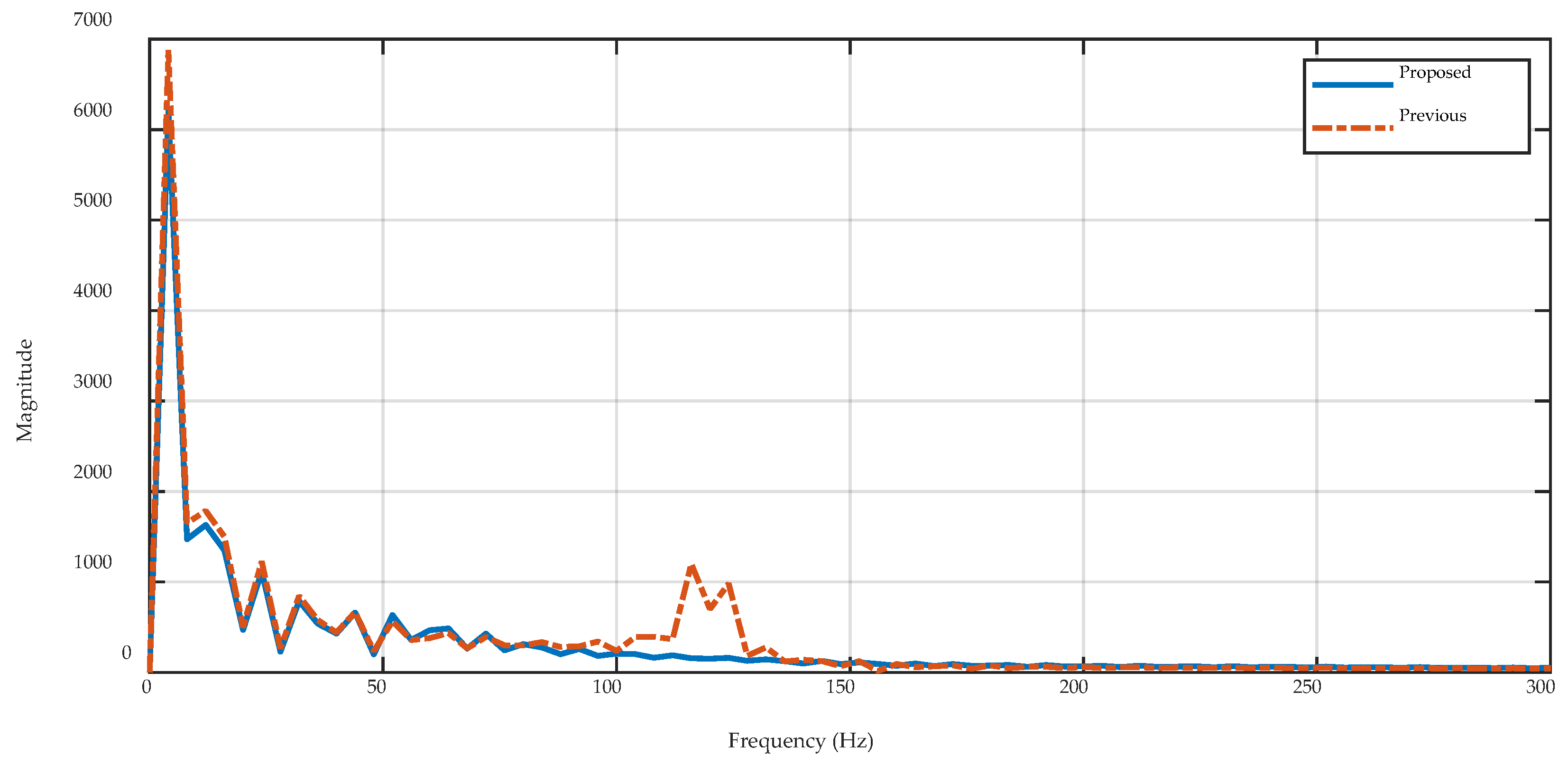
A comparison of the frequency spectrum of the active-power output using the proposed controller and the controller in [19] is provided in Figure 4. In both cases, the dominant oscillatory component occurs at 120 Hz, which is associated with the interaction between positive- and negative-sequence components under grid voltage unbalance. The magnitude of this component is approximately 1.1 kW for the controller in [19], whereas it is reduced to about 0.1 kW with the proposed controller, corresponding to an approximate reduction of 91%. This result confirms that the proposed dual-sequence current control and reference-current generation effectively suppress the double-frequency active-power oscillation.
Figure 4.
Frequency spectrum comparison of the inverter output power obtained using the proposed controller and the controller proposed in [19] under grid voltage unbalance.
From an implementation perspective, the proposed controller requires the solution of the LMI optimization only during the offline controller-design stage. Once the robust gains are obtained, the online control law consists primarily of state-feedback and integral operations for the positive- and negative-sequence controllers. Therefore, the online computational structure remains relatively simple compared with optimization-based controllers that require online prediction or optimization. The robustness is obtained by designing the gains for all 16 vertices of the uncertainty polytope, thereby covering the prescribed variations in filter and grid parameters.
Nevertheless, the present validation is limited to an L-filtered inverter and simulation-based assessment. Detailed harmonic compliance, experimental computational burden, and sensitivity to wider uncertainty ranges have not been investigated in this proceeding paper. These aspects, together with extension to an LCL-filtered topology, will be considered in future work.
5. Conclusions
This paper presented a robust dual-sequence current control strategy for a three-phase grid-following inverter operating under simultaneous grid voltage unbalance and grid impedance uncertainty. The proposed method independently regulates the positive- and negative-sequence currents using state-feedback integral controllers whose gains are synthesized through LMI optimization based on a polytopic uncertainty model. In addition, a sequence-based reference-current generation method was employed to suppress the double-frequency active-power oscillation caused by the interaction between positive- and negative-sequence components.
Simulation results demonstrated that the proposed controller maintains balanced inverter current injection and nearly constant active power despite significant grid voltage unbalance. Compared with the robust controller in [19], the 120 Hz active-power component was reduced from approximately 1.1 kW to 0.1 kW, corresponding to an approximate reduction of 91%. These results demonstrate the advantage of combining robust impedance uncertainty treatment with dual-sequence current regulation for improved power-quality performance.
The present study is limited to an L-filtered inverter and simulation-based validation. Extension to LCL-filtered systems, detailed harmonic assessment, and experimental implementation will be considered in future work.
Author Contributions
Conceptualization, P.S. and C.C.; methodology, P.S. and C.C.; software, S.Y. and S.S.; validation, P.S., H.T. and S.S.; formal analysis, C.C.; investigation, P.S. and H.T.; resources, S.S.; data curation, S.S. and S.Y.; writing—original draft preparation, P.S.; writing—review and editing, C.C.; visualization, H.T. and S.Y.; supervision, C.C.; project administration, S.S.; funding acquisition, C.C. and S.S. All authors have read and agreed to the published version of the manuscript.
Funding
This research received no external funding.
Institutional Review Board Statement
Not applicable.
Informed Consent Statement
Not applicable.
Data Availability Statement
The data used to support the findings of this study are available from the corresponding author upon reasonable request.
Acknowledgments
The authors sincerely acknowledge the National Polytechnic Institute of Cambodia and the members of the Faculty of Electricity for their continuous support, valuable discussions, and encouragement throughout this research.
Conflicts of Interest
The authors declare no conflicts of interest.
References
- Abdelwahab, A.S.; Vokony, I. Beyond Synchronization: The Evolution of Grid-Following to Grid-Forming Inverters and the Quest for Power System Stability. Energy Rep. 2026, 15, 109221. [Google Scholar] [CrossRef] [Scilit]
- Krishnamurthy, N.K.; Pandey, A.K.; Birla, S.; Manikanta, G.; Kumar, S. Smart Inverters Based Technological Advancements in Future Smart Grids for Improved Flexible Renewable Energy Penetration. Discov. Energy 2025, 5, 28. [Google Scholar] [CrossRef] [Scilit]
- Abu Sarhan, M. Performance of Grid-Following and Grid-Forming Inverters Under Unintentional Islanding Events: A Comparative Study. Energies 2026, 19, 250. [Google Scholar] [CrossRef] [Scilit]
- Choeung, C.; Danayiyen, Y.; Srang, S.; Lee, Y.-I. Symmetrical Components-Based Robust Stabilizing Control of a Grid-Connected Inverter under Unbalanced Voltage Sag. J. Eng. 2024, 2024, e70000. [Google Scholar] [CrossRef] [Scilit]
- Ma, K.; Chen, W.; Liserre, M.; Blaabjerg, F. Power Controllability of a Three-Phase Converter with an Unbalanced AC Source. IEEE Trans. Power Electron. 2015, 30, 1591–1604. [Google Scholar] [CrossRef] [Scilit]
- Alharbi, M. Control Approach of Grid-Connected PV Inverter under Unbalanced Grid Conditions. Processes 2024, 12, 212. [Google Scholar] [CrossRef] [Scilit]
- Lu, Y.; Liu, Z.; Meng, S.; Ji, J.; Lyu, J. Deadbeat Predictive Power Control for Vienna Rectifier under Unbalanced Power Grid Condition. Energy Rep. 2021, 7, 257–266. [Google Scholar] [CrossRef] [Scilit]
- Liao, J.; Zhang, Y. A Lyapunov-Stable Direct Deadbeat Control Strategy for Grid-Current-Sensor-Only Active Power Filters. Electronics 2026, 15, 1070. [Google Scholar] [CrossRef] [Scilit]
- Li, Z.; Cheng, W.; Xiao, Q.; Liao, W. Deadbeat Predictive Power Control with Fuzzy PI Compound Controller and Power Predictive Corrector for PWM Rectifier Under Unbalanced Grid Conditions. Int. J. Fuzzy Syst. 2020, 22, 1277–1288. [Google Scholar] [CrossRef] [Scilit]
- Liu, D.; Zhang, H.; Liang, X.; Deng, S. Model Predictive Control for Three-Phase, Four-Leg Dynamic Voltage Restorer. Energies 2024, 17, 5622. [Google Scholar] [CrossRef] [Scilit]
- Erazo-Caicedo, D.; Mojica-Nava, E.; Revelo-Fuelagán, J. Model Predictive Control for Optimal Power Flow in Grid-Connected Unbalanced Microgrids. Electr. Power Syst. Res. 2022, 209, 108000. [Google Scholar] [CrossRef] [Scilit]
- Andrew, E.T.; Ahmed, K.H.; Holliday, D. A New Model Predictive Current Controller for Grid-Connected Converters in Unbalanced Grids. IEEE Trans. Power Electron. 2022, 37, 9175–9186. [Google Scholar] [CrossRef] [Scilit]
- Rath, A.; Srungavarapu, G. Reduced Complexity Model Predictive Direct Power Control for Unbalanced Grid. Electr. Power Syst. Res. 2024, 234, 110563. [Google Scholar] [CrossRef] [Scilit]
- Wang, Y.; Zheng, S.; Zhen, L.; Bi, K. Predictive Direct Power Control of Vienna Rectifier under Unbalanced Grid Conditions. J. Power Electron. 2026. [Google Scholar] [CrossRef] [Scilit]
- Liao, Y.-H.; Yu, M.-H.; Zhang, H.-M. Distorted Unbalanced Grid Voltage Modulated Direct Power Control for Three-Phase Grid-Connected Inverters. IEEE Open J. Power Electron. 2025, 6, 830–848. [Google Scholar] [CrossRef] [Scilit]
- Soth, P.; Noun, S.; Tang, H.; Or, C.; Srang, S.; Danayiyen, Y.; Choeung, C. Robust Power Stabilizing Control of a Grid-Connected Inverter Using Linear Matrix Inequality. Sigma J. Eng. Nat. Sci. 2024, 42, 1367–1377. [Google Scholar] [CrossRef] [Scilit]
- Dupré, G.; Karimi, H.; Karimi-Ghartemani, M.; Saydy, L.; Hoseinizadeh, S.M. An Observer-Based Multivariable Controller for Improved Performance of Voltage Source Converters with LCL Filter Connected to Unbalanced Grid. IEEE Trans. Ind. Appl. 2024, 60, 2225–2237. [Google Scholar] [CrossRef] [Scilit]
- Bimarta, R.; Tran, T.V.; Kim, K.-H. Frequency-Adaptive Current Controller Design Based on LQR State Feedback Control for a Grid-Connected Inverter under Distorted Grid. Energies 2018, 11, 2674. [Google Scholar] [CrossRef] [Scilit]
- Yay, S.; Soth, P.; Tang, H.; Cheng, H.; Ang, S.; Choeung, C. Power Regulation of a Three-Phase L-Filtered Grid-Connected Inverter Considering Uncertain Grid Impedance Using Robust Control. Int. J. Robot. Control. Syst. 2024, 4, 779–794. [Google Scholar] [CrossRef] [Scilit]
- Lim, J.S.; Park, C.; Han, J.; Lee, Y.I. Robust Tracking Control of a Three-Phase DC–AC Inverter for UPS Applications. IEEE Trans. Ind. Electron. 2014, 61, 4142–4151. [Google Scholar] [CrossRef] [Scilit]
- Choeung, C.; Soth, P.; Tang, H.; Srang, S.; Kumar, S.V.; Yay, S. Observer-Based Robust State-Feedback Integral Control of a Standalone Three-Phase LC-Filtered PV Inverter. Int. J. Robot. Control. Syst. 2026, 6, 1777–1800. [Google Scholar]
- Lim, J.S.; Lee, Y.I. Design of a Robust Controller for Three-Phase UPS Systems Using LMI Approach. In Proceedings of the International Symposium on Power Electronics Power Electronics, Electrical Drives, Automation and Motion; IEEE: Sorrento, Italy, 2012; pp. 654–657. [Google Scholar]
- Lim, J.S.; Kim, J.-S.; Lee, Y.I. Robust Tracking Model Predictive Control for Input-Constrained Uncertain Linear Time Invariant Systems. Int. J. Control 2014, 87, 120–130. [Google Scholar] [CrossRef] [Scilit]
- Komurcugil, H.; Kukrer, O. Lyapunov-Based Control for Three-Phase PWM AC/DC Voltage-Source Converters. IEEE Trans. Power Electron. 1998, 13, 801–813. [Google Scholar] [CrossRef] [Scilit]
- Boyd, S.; El Ghaoui, L.; Feron, E.; Balakrishnan, V. Linear Matrix Inequalities in System and Control Theory; Society for Industrial and Applied Mathematics: Philadelphia, PA, USA, 1994; ISBN 978-0-89871-485-2. [Google Scholar]
- Fitri, I.; Kim, J.-S.; Song, H. A Robust Suboptimal Current Control of an Interlink Converter for a Hybrid AC/DC Microgrid. Energies 2018, 11, 1382. [Google Scholar] [CrossRef] [Scilit]
- Lofberg, J. YALMIP: A Toolbox for Modeling and Optimization in MATLAB. In Proceedings of the 2004 IEEE International Conference on Robotics and Automation (IEEE Cat. No.04CH37508); IEEE: Taipei, Taiwan, 2004; pp. 284–289. [Google Scholar]

Disclaimer/Publisher’s Note: The statements, opinions and data contained in all publications are solely those of the individual author(s) and contributor(s) and not of MDPI and/or the editor(s). MDPI and/or the editor(s) disclaim responsibility for any injury to people or property resulting from any ideas, methods, instructions or products referred to in the content. |
© 2026 by the authors. Licensee MDPI, Basel, Switzerland. This article is an open access article distributed under the terms and conditions of the Creative Commons Attribution (CC BY) license.