


Abstract
The growing adoption of hybrid and plug-in electric vehicles increases heat generation in power electronic modules, driving demand for effective thermal management materials and reliable Al/Cu joining methods. However, large-area Al/Cu joints are challenging as conventional brazing requires high temperatures and flux, and fusion welding performs poorly with dissimilar metals. Contact-Reaction Brazing (CRB), which relies on eutectic-phase formation during heating, presents a promising alternative. Direct CRB of AA6063 and Cu might lead to severe aluminum dissolution above 570 °C. To mitigate this, large-area CRB of AA6063/Cu using a 4104 aluminum-foil interlayer is examined. Brazing temperature, holding time, and pressure are systematically varied to evaluate their influence on joint formation. Interfacial microstructures are characterized by SEM and XRD. Shear testing is used to assess fracture behavior and mechanical performance. A satisfactory shear strength of 48.8 MPa is achieved for the AA6063/AA4104/Cu joint under a brazing temperature of 540 °C, a holding time of 10 min, and an applied pressure of 600 Pa.
1. Introduction
With technological advancements, hybrid electric vehicles (HEVs) and plug-in electric vehicles (PEVs) have been developing rapidly. HEVs and PEVs typically employ motor-driven power modules that generate substantial heat, posing significant challenges for thermal management in automotive electronics [1]. Copper is widely used in power-module applications owing to its exceptionally high thermal conductivity. In contrast, aluminum alloys offer adequate thermal performance combined with excellent specific strength and stiffness, as well as low density [2,3,4]. When combined with copper, Al/Cu hybrid structures exploit the complementary advantages of both materials, delivering balanced thermal and electrical performance while significantly reducing weight [5,6].
However, large-area Al/Cu joints made by welding are challenging. The mismatch in physical and chemical properties between the two metals, together with the formation of intermetallic compounds (IMCs) such as Al4Cu9, AlCu or Al2Cu leads to increased brittleness of the welded joint [7]. Various techniques have been employed for welding aluminum and copper to reduce the formation of IMCs, including the gas metal arc welding–brazing method using AlSi12 filler metal [8], friction stir brazing [9], ultrasound-assisted high-frequency induction brazing [10] and flux-free vacuum brazing [11]. In addition, when traditional brazing methods are used to join aluminum and copper, excessively high brazing temperatures are required. Although joints of acceptable quality can be obtained, conventional brazing relies on large amounts of flux and brazing paste, which results in low production efficiency, high cost, severe environmental pollution, and limitations on component size. Traditional fusion welding techniques are unable to produce high-quality Al/Cu dissimilar metal joints and are not suitable for large-area joining. Consequently, their application in industrial manufacturing is significantly constrained.
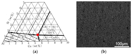
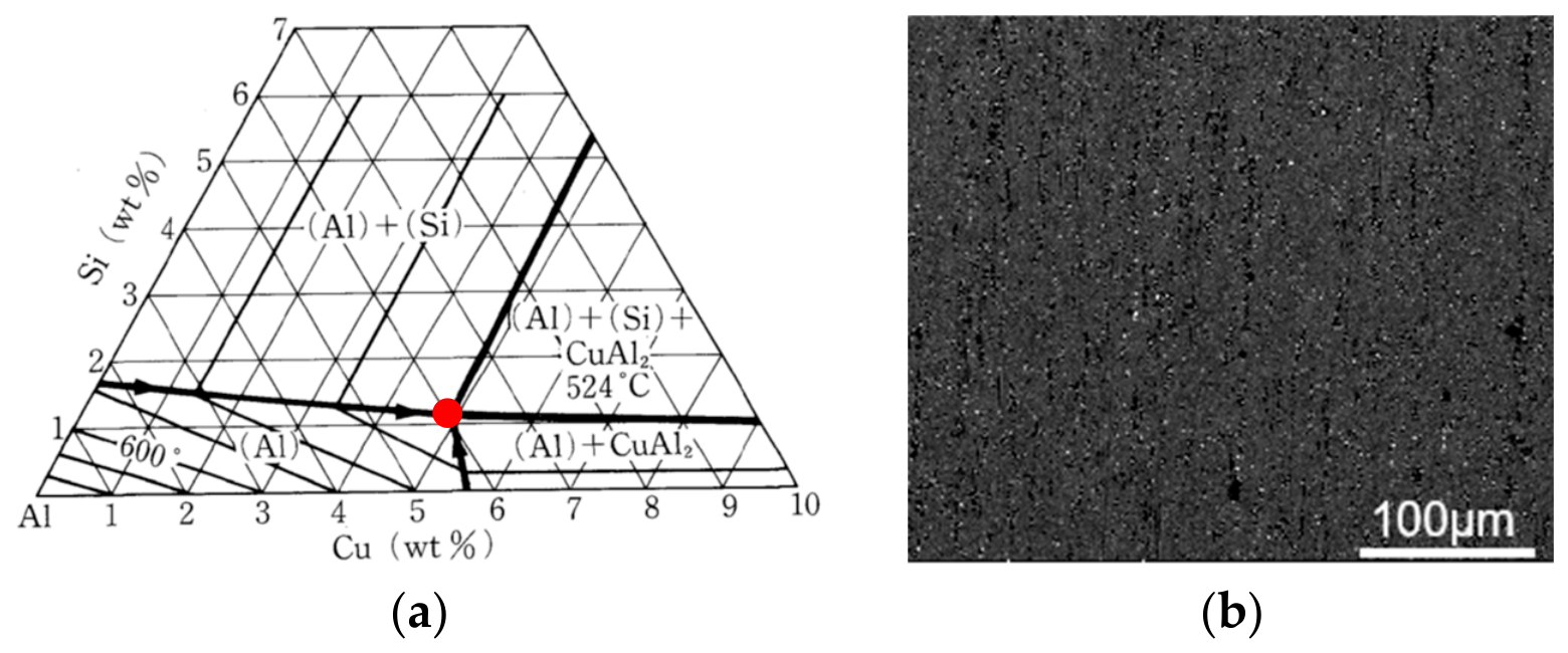
Contact-Reaction Brazing (CRB) is a relatively new joining technology [12]. CRB utilizes eutectic phases formed during the heating of dissimilar metals to join them together. Additionally, the Al–Si–Cu ternary eutectic phase diagram in Figure 1a shows Al, Si, and Cu undergo a ternary eutectic reaction at 524 °C (marked by the red circle). The eutectic reaction temperature can be reduced by 24 °C if an Al interlayer is used, resulting in a significant decrease in the required brazing temperature. In this work, large-area CRB of AA6063/Cu using a 4104 aluminum-foil interlayer will be examined. Brazing process parameters are systematically varied to evaluate their influence on joint formation. Fracture behavior and mechanical performance of the joint will also be evaluated.
Figure 1.
(a) Al–Si–Cu ternary eutectic phase diagram [13] and (b) SEM image of AA4104 foil.
2. Experimental
2.1. Materials and Characterization
Pure Cu and AA6063 are used as the base metals, with dimensions (length × width × thickness) of 40 mm × 40 mm × 4 mm and 80 mm × 80 mm × 4 mm, respectively. AA4104 foil with a thickness of 100 µm is used as the interlayer, with its SEM microstructure shown in Figure 1b. The compositions of the aluminum alloys are given in Table 1.
Table 1.
The chemical compositions of aluminum alloys (wt.%).
A Leica optical microscope (LEICA DMI5000M, Leica Microsystems Wetzlar GmbH, Wetzlar, Germany) is used to observe the optical microstructure of the materials. An FEI Scanning Electron Microscope (SEM) (Quanta 250 FEG, FEI Company, Hillsboro, OR, USA) with a maximum magnification of up to 100,000× is used to analyze the interfacial microstructures of the metal joints and fracture surfaces. An Oxford Energy-Dispersive Spectrometer (EDS) (Ultim Max 100, Oxford Instruments, Abingdon, UK) is used to analyze the local chemical composition at the joint interface and for line-scan analyses for quantitative assessment. The shear strength of the Al/Cu joints is measured using an electro-hydraulic universal testing machine (ZX-529-066, SINOTEST Equipment Co., Ltd., Changchun, China) at a loading rate of 1 mm/min. The specimens have an overlap or planar area of 40 × 40 mm2 (1600 mm2) and a thickness of around 8 mm (across two layers of AA6061 and copper). Shear strength is calculated as the maximum load divided by this area.
2.2. Material Preprocessing and Postprocessing
Before brazing, the AA6063 and the copper plates are polished with 800-grit sandpaper to reduce or remove dense oxide film, followed by cleaning with anhydrous ethanol. Further, the AA6063 plate, the AA4104 foil and the pure copper plate are ultrasonically cleaned in acetone, dried with a blower, and placed on a graphite plate. After brazing is completed, the specimens are furnace-cooled to below 100 °C, removed, and then subjected to cutting, polishing, and analysis.
2.3. Brazing Experiments
A vacuum brazing furnace (2LQ-120, Wuxi Sifang Vacuum Equipment Co., Ltd., Wuxi, China) is used for the Al/Cu contact-reaction-brazing experiments. During operation, a weighting block is positioned on the metals to be brazed, and the assembly is then loaded into the vacuum furnace with a vacuum pressure of 3.0 × 10⁻³ Pa. The furnace is first heated to a specified temperature and held to ensure a more uniform internal temperature, allowing the Al–Cu assembly to approach the target brazing temperature. Subsequently, heating proceeds at a rate of 7 °C/min. The specimens are cooled with the furnace afterward. During brazing, a nominal pressure is applied by placing calibrated weights on the upper surface of Cu. The applied pressure is calculated as the ratio of the applied weight to the nominal contact area (40 × 40 mm2).
Three main brazing process parameters—brazing temperature, holding time and applied pressure—are chosen to examine their effects on interfacial microstructures and joint mechanical properties. The brazing temperatures are varied among 530 °C, 540 °C and 550 °C under a holding time of 10 min and an applied pressure of 600 Pa. To study the influence of holding time, durations of 5 min, 10 min, and 15 min are selected at a constant brazing temperature of 540 °C and pressure of 600 Pa. Additionally, the influence of applied pressure is examined by varying pressure at 300, 600, 900, and 1200 Pa under a brazing temperature of 540 °C and a holding time of 10 min.
3. Results and Discussion
3.1. Effects of the Brazing Process Parameters on the Microstructure of the Joint Interface
3.1.1. Effects of the Brazing Temperature
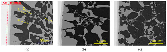
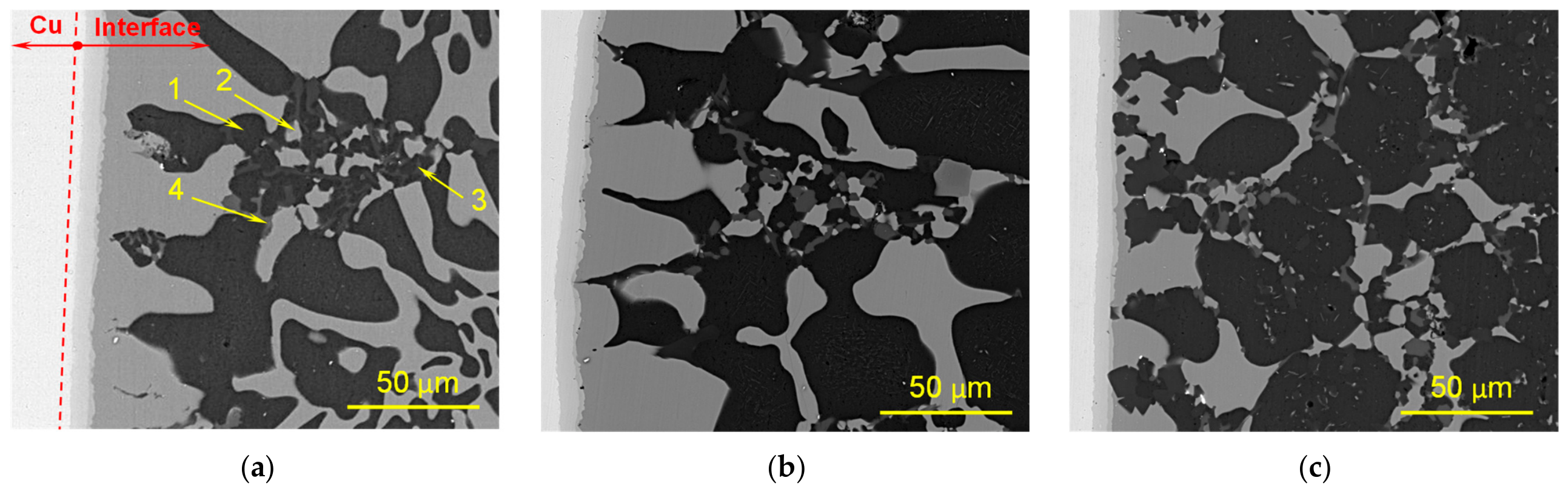
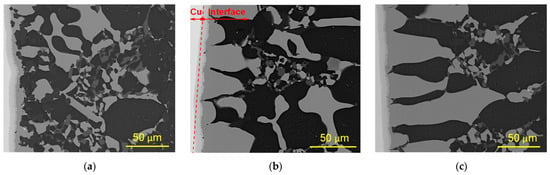
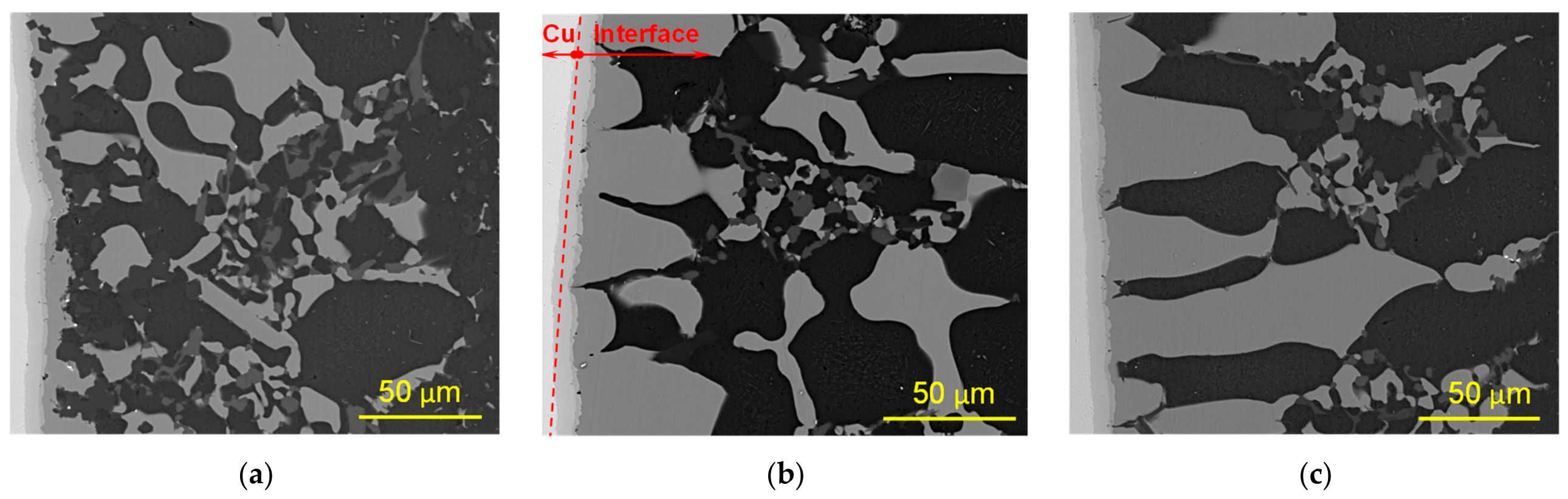
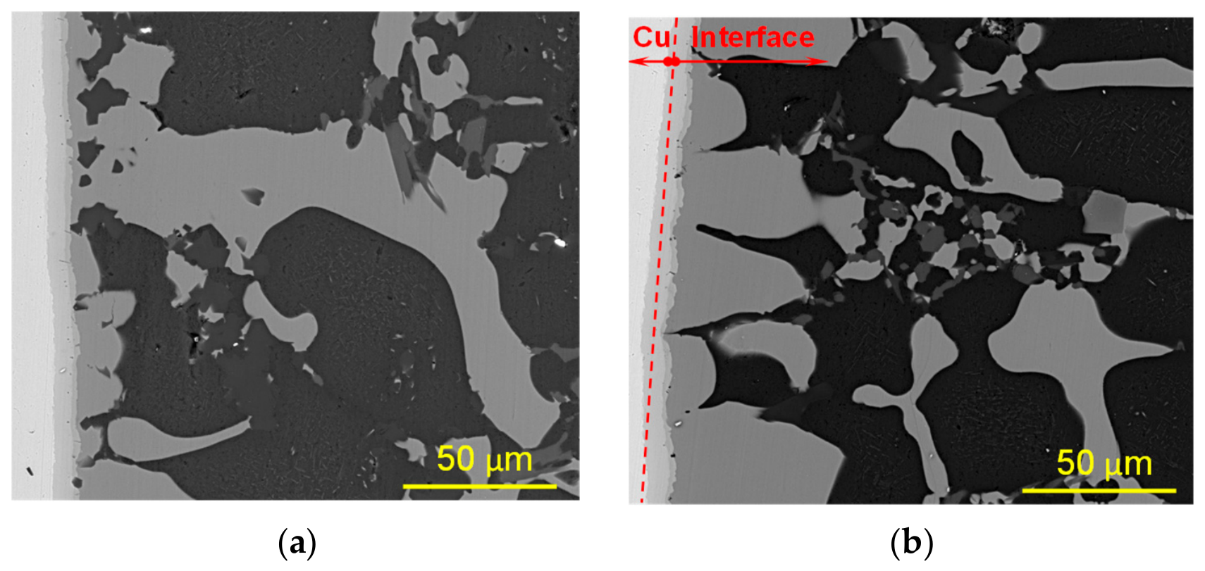
As shown in Figure 2a, the joint can be clearly divided into five distinct regions: (from left to right) the pure Cu region, the intermetallic compound (IMC) region, the eutectic region, the solid-solution region, and the AA6063 bulk region. At the Cu side, two light-gray, layered phases containing small dispersed voids are observed. To the right of this layered region, a bright-gray phase appears with a characteristic saw-tooth morphology, and the bright-gray phase in the weld center exhibits a discontinuous distribution. Near the saw-toothed bright-gray phase, block-shaped dark phases are present. Around the discontinuous bright-gray regions at the weld center, additional discontinuous block-shaped dark phases and dark-gray phases can be observed.
Figure 2.
SEM images of the interfaces of the AA6063/AA4104/Cu joint under a holding time of 10 min and an applied pressure of 600 Pa, at brazing temperatures of: (a) 550 °C; (b) 540 °C; (c) 530 °C.
The weld seam width remains relatively narrow for joints brazed at lower temperature. Kirkendall voids [14] are observed within the layered AlCu and Al4Cu9 intermetallic compounds. These voids form due to the unequal diffusion rates of Al and Cu atoms (Cu diffuses much faster than Al). As the brazing temperature increases, the diffusion rates of Al and Cu accelerate, resulting in a reduction of Kirkendall voids. The jagged Al2Cu phase continues to grow by incorporating the continuously diffusing Al and Cu atoms. The weld center exhibits a typical Al–Cu–Mg–Si quaternary eutectic structure.
At 550 °C, the weld seam widens significantly with fewer voids formed. The weld center locally exhibits the characteristic morphology of an Al–Cu eutectic, which forms during cooling and solidification when the local concentrations of Al and Cu reach the eutectic composition. As solidification progresses and the temperature continues to decrease, these eutectic phases further grow by consuming the surrounding residual liquid phase. The phase types are estimated through elemental analysis, as shown in Table 2, on EDS results obtained from the selected representative points labeled 1–4 in Figure 2a. These suggest that higher brazing temperatures promote the formation of more liquid phase, allowing it to fully spread across the interface. During subsequent cooling and solidification, once the local concentrations of Al and Cu reach the required levels, Al–Cu eutectic structures precipitate.
Table 2.
EDS analysis from the selected representative points in Figure 2a.
3.1.2. Effects of the Holding Time
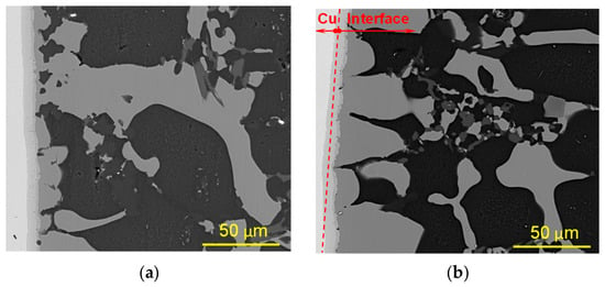
As shown in Figure 3, a high concentration of Si is observed near the Cu side when the holding time is short. The Si appears as black blocky phases surrounded by coarse Al2Cu, which can be estimated by EDS as an Al–Si–Cu ternary eutectic. This is attributed to the initial high Si content in the AA4104 interlayer (9.0–10.5 wt.%), limited diffusion due to a short holding time, and the formation of a Cu-rich composition gradient, which promotes local enrichment and preferential formation of Si-rich eutectic during solidification.
Figure 3.
SEM images of the interfaces of AA6063/AA4104/Cu near the Cu side under a brazing temperature of 540 °C and a pressure of 600 Pa, with holding times of: (a) 5 min; (b) 10 min; (c) 15 min.
When the holding time is extended to 15 min, the weld seam widens, and the saw-toothed Al2Cu phase grows significantly, leading to a denser microstructure. This is due to continued atomic diffusion, which promotes further dissolution of 6063 Al and composition evolution at the interface. Meanwhile, the Cu-rich region on the Cu side favors continued growth of Al2Cu. This suggests that partial isothermal solidification may occur at longer holding times, as Al and Cu diffuse more readily than Si, although compositional gradients are still retained.
3.1.3. Effects of the Applied Pressure
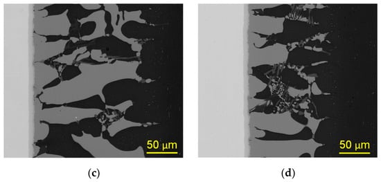
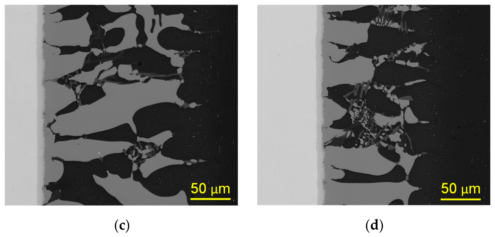
Figure 4 shows that voids are present at the interface when the applied pressure is 300 Pa, and these voids decrease as the pressure increases. Once the pressure is raised to 900 Pa, the weld seam width increases significantly, indicating that higher pressure accelerates atomic diffusion. After the AA4104 foil is completely consumed, further reaction with AA6063 occurs, causing the weld seam to continue widening. When the pressure is increased to 1200 Pa, the Al2Cu phase grows noticeably, but the weld width shows no significant increase. This is because the primary Al2Cu and α-Al solid solution form a continuous network, which hinders atomic diffusion. Since reaction with AA6063 requires the atomic concentration to reach a certain threshold, the available diffusion time becomes insufficient. Once cooling and solidification begin, dissolution of AA6063 no longer occurs.
Figure 4.
SEM images of interfaces of Al/Cu joint under brazing temperature of 540 °C and holding time of 10 min, with applied pressures of: (a) 300 Pa; (b) 600 Pa; (c) 900 Pa; (d) 1200 Pa.
3.2. Fracture Behavior and Fracture Surface Morphology of the Joints
3.2.1. Fracture Behavior
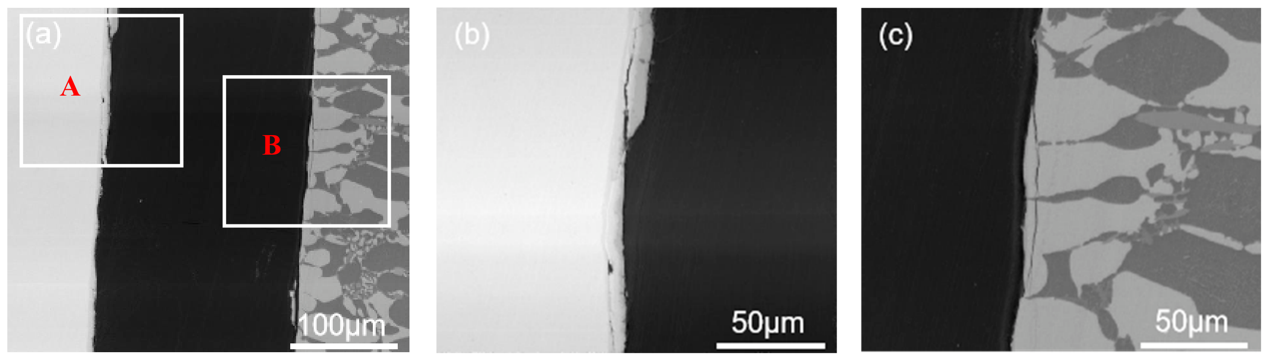
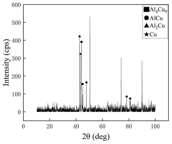
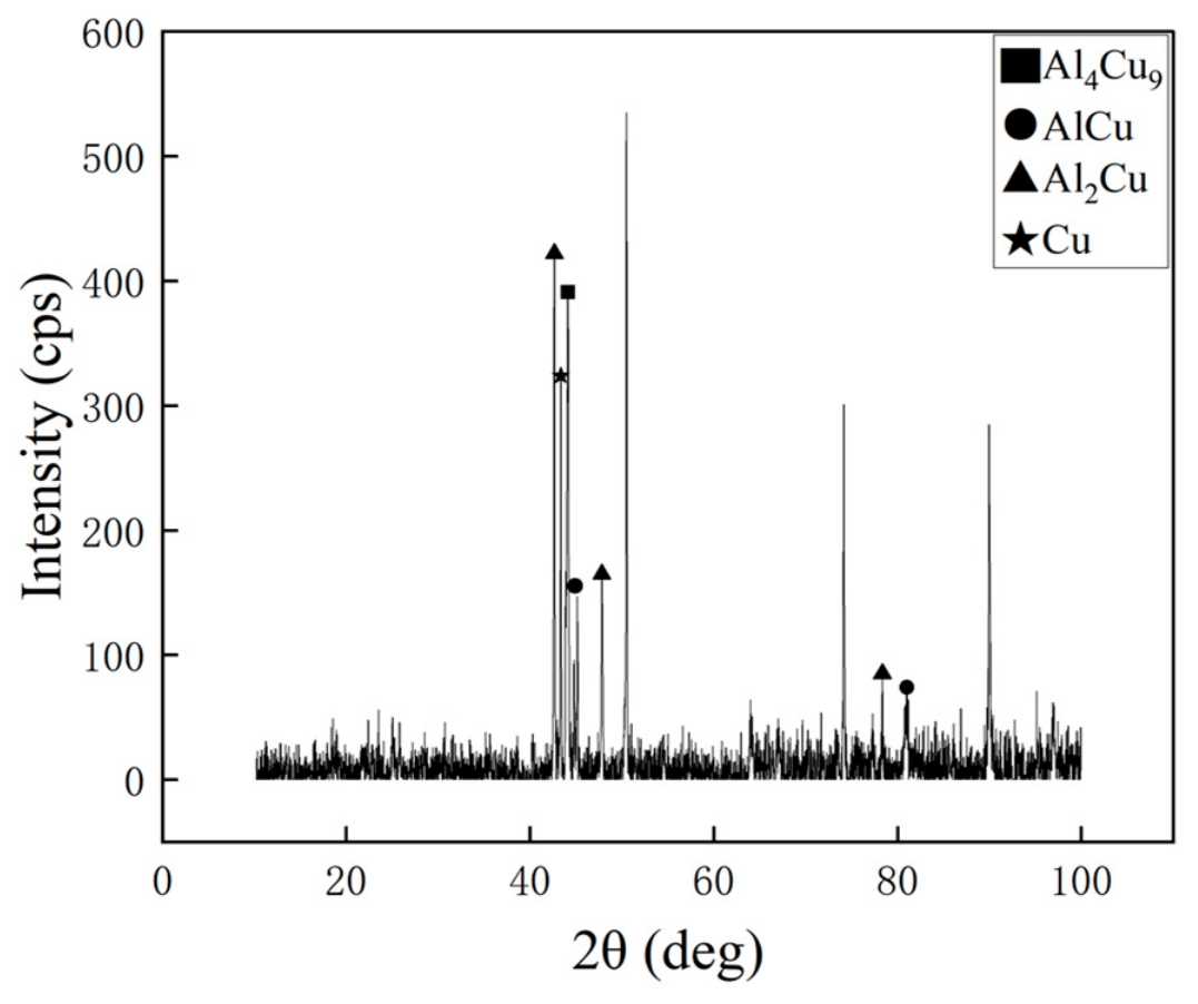
Figure 5 presents two typical fractured interfaces of the AA6063/AA4104/Cu joint made under the brazing condition in Figure 2b, using a shear test. Based on the XRD analysis at the cross-section of the joint in Figure 6, the fracture region contains AlCu, Al2Cu, and Al4Cu9 phases. Because the Al2Cu phase within the intermetallic compound interfacial layer is hard and brittle, significant stress concentrations develop when the joint is loaded, allowing cracks to initiate readily and propagate rapidly. On the Cu side shown in Figure 5b, the crack advances into the Al4Cu9 phase. This occurs because the AlCu layer is the thinnest IMC sublayer and cracks more easily penetrate it and subsequently propagate into the adjacent Al4Cu9 phase. In contrast, near the AA6063 side in Figure 5c, a fracture initiates in the primary θ-Al2Cu phase next to the eutectic region and continues to propagate through this primary phase without extending into the eutectic microstructure at the weld center.
Figure 5.
Fracture locations of the AA6063/AA4104/Cu joint: (a) at the joint; (b) near the Cu side (marked by the featured region A); (c) near the Al side (marked by the featured region B).
Figure 6.
XRD analysis results at the lateral cross-section of the AA6063/AA4104/Cu joint.
3.2.2. Fracture Surface Morphology
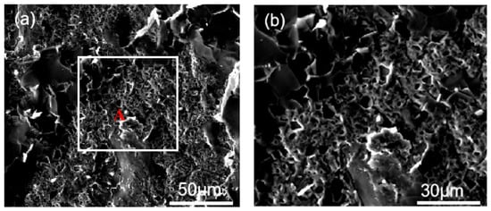
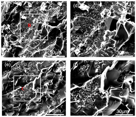
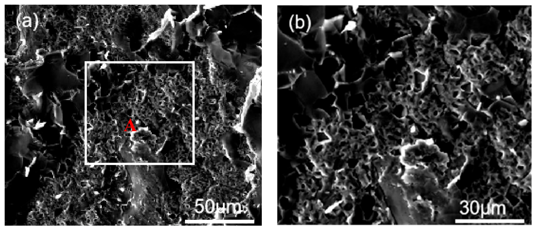
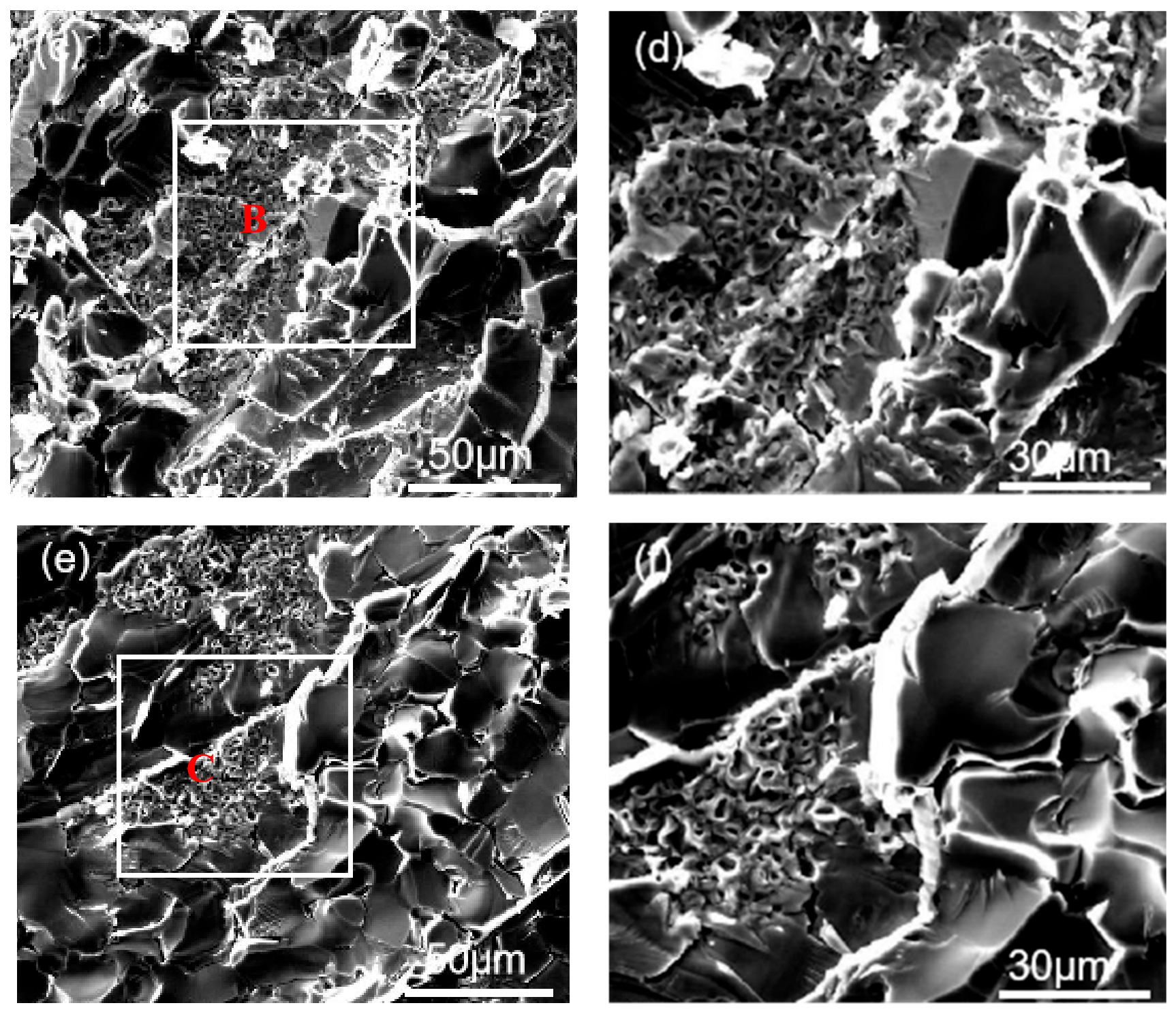
The Cu-side fracture morphologies of the joints brazed at 530 °C, 540 °C, and 550 °C under a holding time of 10 min and an applied pressure of 600 Pa are shown in Figure 7. With increasing brazing temperature, the fracture location of the joints does not exhibit any significant change. Numerous voids are observed in Figure 7b. This is consistent with the previously described microstructural features where Kirkendall voids are identified within the IMC layer. Under external loading, cracks easily propagate from these voids, which may act as crack-initiation sites.
Figure 7.
Fracture morphologies of the AA6063/AA4104/Cu joint near the Cu side: (a) at a 530 °C brazing temperature; (b) the featured region A in (a); (c) at a 540 °C brazing temperature; (d) the featured region B in (c); (e) at a 550 °C brazing temperature; (f) the featured region C in (e). The scale bars in (a,c,e) represent 50 μm, while those in (b,d,f) represent 30 μm.
The fracture surface of the joint brazed at 540 °C in Figure 7c exhibits smooth facets accompanied by crack propagation. At a higher brazing temperature (550 °C in Figure 7e), the fracture surface shows large smooth cleavage planes, river patterns, and step-like features, as well as elongated tearing ridges. No dimples or ductile fracture features are observed. Overall, the fracture morphology corresponds to a cleavage-type brittle fracture.
3.3. Mechanical Properties
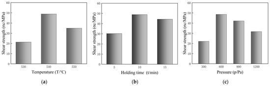
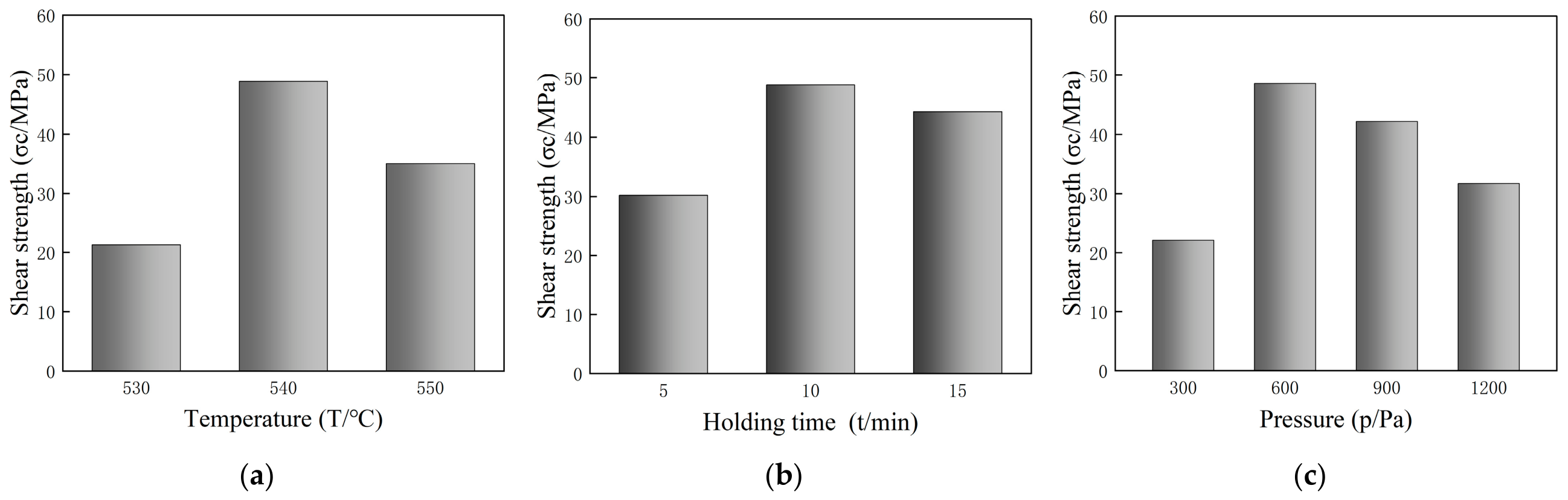
For each brazing condition, three specimens are tested, and the average shear strength value with standard deviation (±1–3 MPa) is reported. As shown in Figure 8, the shear strength first increases and then decreases with rising brazing temperature. The joint achieves its maximum shear strength of 48.8 MPa at 540 °C, whereas at 530 °C, the strength is only 21.3 MPa where numerous voids are present in Figure 7a, which severely degrade the shear strength.
Figure 8.
Relationship between shear strength and the process parameters of: (a) brazing temperature; (b) holding time; (c) applied pressure.
With increasing holding time, the joint achieves its maximum shear strength at a holding time of 10 min, while the lowest value of 30.2 MPa occurs at 5 min. As the applied pressure increases, the maximum shear strength of 48.8 MPa is obtained at 600 Pa, where a sound metallurgical bond forms at the interface. Under a pressure of 300 Pa, insufficient atomic diffusion combined with the presence of welding defects leads to reduced joint strength. In contrast, increasing the applied pressure to 1200 Pa enhances point-to-point contact between the base metals, thereby promoting Cu and Al atomic diffusion and accelerating the growth of IMCs. However, once the IMC layer becomes excessively thick, the shear strength of the joint begins to decrease.
It is noted that the applied pressure (300–1200 Pa) during brazing appears low in this study; it is sufficient because brazing is fundamentally driven by liquid-phase wetting and capillary forces rather than external pressure. Future work could investigate whether introducing rotational movement of the applied weight in brazing may improve the homogenization of joint properties, akin to the rotating-platen approach reported in [15].
4. Conclusions
Contact-reaction brazing is employed to fabricate an AA6063–Cu joint via an AA4104 foil interlayer. The main conclusions are summarized as follows:
- Large-area AA6063 and copper blocks are successfully joined using 100 μm thick AA4104 foil through vacuum contact-reaction brazing, producing a sound metallurgical bonding interface.
- The key brazing process parameters are examined by varying brazing temperature, applied pressure and holding time. The experiments identify the optimal conditions as a brazing temperature of 540 °C, a holding time of 10 min, and an applied pressure of 600 Pa, under which the joint achieves a maximum shear strength of 48.8 MPa.
- Fracture of the joint during the shear test occurs within the intermetallic compound layer and exhibits a distinctly brittle fracture mode.
Author Contributions
Conceptualization, L.W.; methodology, H.Z., T.N., Z.W., L.W., M.S. and X.M.; software, H.Z. and T.N.; validation, H.Z., T.N., Z.W., L.W. and X.M.; formal analysis, H.Z., T.N., Z.W., L.W. and X.M.; investigation, H.Z., T.N., Z.W., L.W., M.S., D.R. and X.M.; resources, L.W., D.R. and X.M.; data curation, H.Z., T.N., Z.W., L.W. and X.M.; writing—original draft preparation, H.Z., T.N., Z.W., L.W. and X.M.; writing—review and editing, H.Z., T.N., Z.W., L.W., M.S., D.R. and X.M.; visualization, H.Z., T.N., Z.W., L.W. and X.M.; supervision, L.W., M.S. and X.M.; project administration, L.W. and X.M.; funding acquisition, L.W., D.R. and X.M. All authors have read and agreed to the published version of the manuscript.
Funding
This research was partially funded by the National Natural Science Foundation of China (grant no. 51775249), SFI Future Aluminium Structures (FAST) funded by the Research Council of Norway (grant no. 360119), and the Horizon Europe research and innovation program of the European Union under the DataPACT project (grant no. 101189771).
Institutional Review Board Statement
Not applicable.
Informed Consent Statement
Not applicable.
Data Availability Statement
The research data can be provided upon request.
Conflicts of Interest
The authors declare no conflicts of interest.
References
- Moreno, G.; Narumanchi, S.; Feng, X.; Anschel, P.; Myers, S.; Keller, P. Electric-Drive Vehicle Power Electronics Thermal Management: Current Status, Challenges, and Future Directions. J. Electron. Packag. 2021, 144, 011004. [Google Scholar] [CrossRef] [Scilit]
- Amatullah, M.; Jan, M.; Farooq, M.; Zargar, A.S.; Maqbool, A.; Khan, N.Z. Effect of Tool Rotational Speed on the Friction Stir Welded Aluminum Alloys: A Review. Mater. Today Proc. 2022, 62, 245–250. [Google Scholar] [CrossRef] [Scilit]
- Shi, M.; Chen, J.; Wang, W.; Li, J.; Mao, W.; Li, S.; Ma, X. Evolution of Precipitates in a Mechanical Vibration-Assisted Metal Inert Gas Welded Joint of 6082-T6 Aluminum Alloy Made with an ER5356 Filler Wire. J. Mater. Eng. Perform. 2025, 34, 11733–11741. [Google Scholar] [CrossRef] [Scilit]
- Shi, M.; Li, J.; Mao, W.; Yang, Z.; Ma, X. Strengthening the HAZ of an MIG Welded Joint of 6082-T6 Aluminum Alloy via Mechanical-Thermal Hybrid Aging Treatment. J. Adhes. Sci. Technol. 2024, 38, 2241–2255. [Google Scholar] [CrossRef] [Scilit]
- Fang, Y.; Jiang, X.; Mo, D.; Zhu, D.; Luo, Z. A Review on Dissimilar Metals’ Welding Methods and Mechanisms with Interlayer. Int. J. Adv. Manuf. Technol. 2019, 102, 2845–2863. [Google Scholar] [CrossRef] [Scilit]
- Sadeghian, A.; Iqbal, N. A Review on Dissimilar Laser Welding of Steel-Copper, Steel-Aluminum, Aluminum-Copper, and Steel-Nickel for Electric Vehicle Battery Manufacturing. Opt. Laser Technol. 2022, 146, 107595. [Google Scholar] [CrossRef] [Scilit]
- Carlone, P.; Astarita, A.; Palazzo, G.S.; Paradiso, V.; Squillace, A. Microstructural Aspects in Al–Cu Dissimilar Joining by FSW. Int. J. Adv. Manuf. Technol. 2015, 79, 1109–1116. [Google Scholar] [CrossRef] [Scilit]
- Zhou, X.; Zhang, G.; Shi, Y.; Zhu, M.; Yang, F. Microstructures and Mechanical Behavior of Aluminum-Copper Lap Joints. Mater. Sci. Eng. A 2017, 705, 105–113. [Google Scholar] [CrossRef] [Scilit]
- Zhou, Y.; Chen, S.; Wang, D.; Li, R.; Liu, B.; Pu, J.; Yang, Z. Effect of Shoulder Diameter on the Force Generation, Microstructure and Mechanical Properties of Friction Stir-Brazed Aluminium Alloy and Copper with Ultrahigh Rotation Speed. Acta Metall. Sin. (Engl. Lett.) 2020, 33, 154–164. [Google Scholar] [CrossRef] [Scilit]
- Liang, Y.; Pan, J.; Zhang, H.; Huang, P.; Wang, J.; Shi, Y.; Chen, L. Ultrasonic-Assisted Semi-Solid Forming Method and Microstructure Evolution of Aluminum/Copper Brazed Joints. Metals 2020, 10, 223. [Google Scholar] [CrossRef] [Scilit]
- Sommer, A.-K.; Türpe, M.; Füssel, U.; Grünenwald, B. Considerations on a New Brazing Concept for Vacuum Brazing of Aluminium and Copper. Weld. World 2020, 64, 1589–1596. [Google Scholar] [CrossRef] [Scilit]
- Yang, T.; Wang, K.; Zhang, D.; Huang, J. Contact-Reaction Brazing of an AZ31 Magnesium/3003 Aluminum Alloy Using a Silver-Copper-Zinc Interlayer. J. Mater. Process. Technol. 2017, 249, 531–537. [Google Scholar] [CrossRef] [Scilit]
- Kitaoka, S.; Fujikura, C.; Kamio, A. Aluminum-Silicon Alloys. J. Jpn. Inst. Light Met. 1988, 38, 426–446. [Google Scholar] [CrossRef] [Scilit]
- Tu, K.N. Recent Advances on Electromigration in Very-Large-Scale-Integration of Interconnects. J. Appl. Phys. 2003, 94, 5451–5473. [Google Scholar] [CrossRef] [Scilit]
- Ma, X.; Barnett, M.R.; Kim, Y.H. Experimental and Theoretical Investigation of Compression of a Cylinder Using a Rotating Platen. Int. J. Mech. Sci. 2003, 45, 1717–1737. [Google Scholar] [CrossRef] [Scilit]

Disclaimer/Publisher’s Note: The statements, opinions and data contained in all publications are solely those of the individual author(s) and contributor(s) and not of MDPI and/or the editor(s). MDPI and/or the editor(s) disclaim responsibility for any injury to people or property resulting from any ideas, methods, instructions or products referred to in the content. |
© 2026 by the authors. Licensee MDPI, Basel, Switzerland. This article is an open access article distributed under the terms and conditions of the Creative Commons Attribution (CC BY) license.