


Abstract
This paper investigates the design of aluminium I-beams under major axis bending, fabricated by MIG welding three plates to form the section. The study focuses on beam sizes relevant to pedestrian bridges, with depths ranging from 508 mm to over 2540 mm. The analysis is limited to local buckling behaviour. A total of 600 geometrical material non-linear imperfection analysis-GMNIA and linear buckling analysis-LBA reference numerical results were obtained from validated non-linear shell finite element models. The influence of the heat-affected zone (HAZ) is shown to be pronounced and detrimental to the resistance of welded aluminium beams. Unlike in steel beams, where buckling often governs, local buckling modes in aluminium members may arise but are typically dominated by HAZ-related failure. The effect of strain hardening on the behaviour and resistance of aluminium alloys is examined and compared with current design approaches, which typically assume an idealised plastic plateau similar to steel. The results show that strain hardening significantly enhances resistance and is not captured by existing design methods. The effect of residual stresses in welded aluminium members is also investigated. The results indicate that MIG-induced residual stresses are sufficiently small and have a negligible influence on both structural behaviour and strength. Their effect can be conservatively accounted for by increasing the amplitude of initial geometric imperfections. The study shows that current design recommendations are inconsistent and mostly unsafe for welded aluminium beams bridge sections governed by local buckling. The findings provide improved insight into the behaviour and resistance of such members and contribute to more accurate and efficient design methods.
1. Introduction
Aluminium alloys offer a compelling combination of properties, including low density, high strength-to-weight ratio, good formability, corrosion resistance, and full recyclability, making them attractive for structural applications [1]. Since the mid-20th century, they have been widely used in building and pedestrian infrastructure, particularly in grid and shell-type structures [2]. Research in this field led to key milestones such as the ECCS recommendations in the 1970s [2], followed by U.S. Aluminium Association specifications [3], and later formal standards including CSA S157 and Eurocode 9 [4,5].
Despite these advances, the design of welded aluminium members—especially MIG-welded I-beams assembled from three plates—remains insufficiently understood. These members, commonly used in pedestrian bridges, are prone to interacting failure modes such as local buckling and strength reduction in the heat-affected zone (HAZ) [6]. Unlike steel, where buckling typically governs, HAZ softening plays a critical role in aluminium, yet is often treated conservatively in design codes for small sections [6].
Large aluminium I-beams cannot be produced by extrusion, which is generally limited to depths of about 300 mm [7,8], whereas bridge girders typically range from 500 mm to over 2500 mm [1,9]. As a result, MIG welding with fillet welds is used to fabricate such sections. This study investigates the combined effects of strain hardening, HAZ softening, and residual stresses on structural performance. While existing standards tend to conservatively predict the strength of small extruded sections [6], many cases examined here were found to be unsafe, highlighting a significant gap between codified provisions and the actual behaviour of welded aluminium bridge girders.
The study evaluates beam strength through an extensive numerical investigation using validated non-linear shell finite element models, generating over 600 GMNIA and LBA results. Current design methods are critically assessed, and their limitations for welded aluminium I-beams in pedestrian bridge applications are identified and discussed.
2. FE Shell Non-Linear Models
2.1. General
The buckling collapse behaviour of aluminium I-beams with stiffeners was simulated using the finite element software FINELg v9.0 [10]. The finite element (F.E.) mesh was carefully defined to ensure that discrete elements fully capture the extent of the heat-affected zone (HAZ), with convergence studies confirming that this discretisation provides a sufficiently accurate representation of the HAZ behaviour. The F.E. models simulated the aluminium beams under three-point bending arrangements for welded aluminium I-beams. The beams were modelled under fork support conditions at both ends, which restrain lateral displacement and twist while permitting free warping and rotation about the major axis. Lateral supports were also imposed at the beam ends and at the load application point to prevent out-of-plane displacement. The load was applied as a concentrated force at mid-span, consistent with the three-point bending arrangement. This setup was adopted to investigate the flexural and local buckling behaviour of the sections under realistic support and loading conditions.
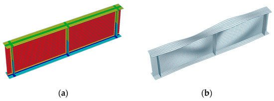
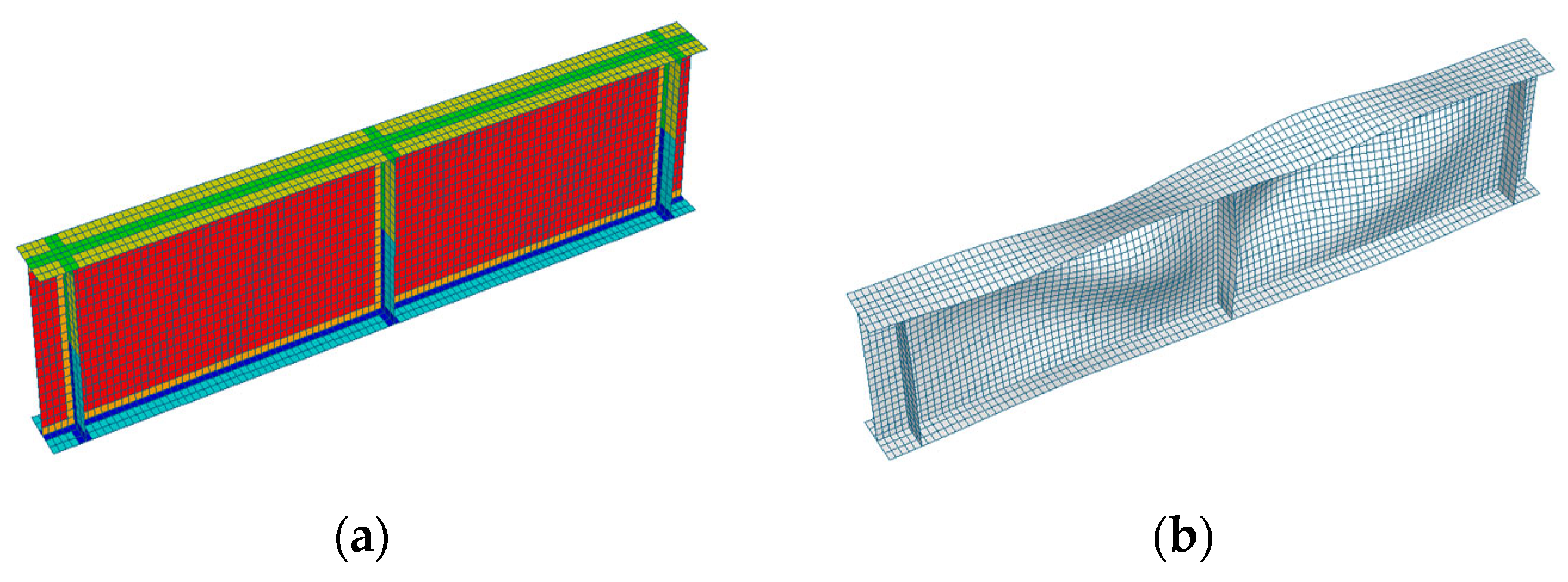
The baseline finite element models incorporate three key material and fabrication effects: strain hardening, heat-affected zone (HAZ) softening, and residual stresses. To evaluate the individual contribution of each effect, additional models were developed in which each of these three parameters was excluded one at a time, while the remaining two were retained. The HAZ width (20–40 mm) was determined in accordance with CSA S157 and Eurocode 9, where the extent of the softened region is defined as a function of the web and flange plate thicknesses; due to space limitations, the reader is referred to these standards for further details. Initial geometric imperfections were adopted affine to the first LBA eigenmode; welding residual stresses and HAZ softening effects were also incorporated into the numerical models. The modulus of elasticity of the aluminium alloy is taken as 70,000 N/mm2, and the material stress-strain response is represented by the Ramberg-Osgood relationship, characterised by the yield stress (σ0.2) and strain hardening factor (n, nw); Fy and Fu are yield strength and ultimate strength of the regular material, while Fwy and Fwu are yield strength and ultimate strength for HAZ, respectively, with relevant parameters summarised in Table 1, for aluminium alloys where the properties in CSA S157 are the same as the properties in Eurocode 9. The geometry, mesh discretisation, stiffener configuration, area of HAZ, and applied initial imperfection of a representative model are illustrated in Figure 1.
Table 1.
Material law parameters.
Figure 1.
Aluminium I-beams (a) geometry, mesh discretisation, stiffener configuration and distribution of HAZ (green and blue areas); (b) initial imperfection in a representative model (magnified).
2.2. Residual Stresses
The influence of welding residual stress on the ultimate capacity of rectangular plates with heat-affected zones (HAZs) has been reported to be relatively minor [11,12]. Nevertheless, the effect of weld-induced residual stress on the buckling strength of stiffened panels is explicitly considered in the present study and simulated in F.E. models with particular attention given to local buckling modes in thin-walled stiffened configurations. Weld-induced geometric imperfections and compressive residual stresses within the stiffeners are known to reduce the load-carrying capacity—whether governed by local buckling or yielding—and can subsequently trigger the progressive collapse of the stiffened plates. In this study, the tensile residual stress is assumed to be 30% of the aluminium alloy yield strength—as reported by Shusen et al. [13]—while the corresponding compressive residual stress is determined through equilibrium considerations based on the cross-sectional area and the magnitude of the tensile residual stress.
To isolate and quantify the contribution of residual stress to the structural response, a parallel set of numerical models is developed without residual stresses. A direct comparison between the two cases enables a systematic assessment of the influence of welding residual stress on the strength and buckling behaviour of welded aluminium.
2.3. Heat-Affected Zone (HAZ) Properties
For aluminium alloys of the 6xxx series, the material strength within the HAZ can be locally reduced to as low as 50% of that of the parent material. Consequently, neglecting the influence of the HAZ leads to a significant overestimation of the ultimate tensile load-carrying capacity in fillet-welded aluminium 6061-T6 and 6063-T6 joints, as demonstrated by Matusiak [14]. Furthermore, Kristensen and Moan [15] showed numerically that the ultimate strength of plates in aluminium alloy series 5xxx and 6xxx under axial compression was reduced by 10% to 35%, corresponding to HAZ strength reduction factors of 10% and 50%, respectively. In the present study, HAZ was simulated by F.E. models with information from CSA S157 and Eurocode 9.
2.4. Validation of the F.E. Models
To ensure the robustness of the numerical formulation, the developed finite element model was validated against laboratory tests on steel I-section beams reported by Emad et al. [16], due to the absence of experimental data for welded aluminium I-girders of comparable depth. The experimental phase of this study involved I-girder specimens manufactured from HPS-100W steel, which were loaded to failure under three-point bending to replicate the negative flexure conditions occurring at an interior pier of a bridge girder. The governing failure mode was found to be inelastic local buckling of both the web and flanges. Although the present work addresses welded aluminium bridge girders, these steel experiments were selected as a reference because the underlying failure mechanisms—local web buckling, flange–web interaction, and post-yield deformation—are governed primarily by plate slenderness and geometric instability rather than by material properties alone. Consequently, the well-documented steel test results provide a reliable benchmark against which the numerical model can be validated in terms of its ability to capture the correct local buckling behaviour. The measured geometric properties, as reported in Table 2, were directly implemented into the numerical models.
Table 2.
Measured geometrical properties of specimens and test vs. F.E. results.
The experimental setup, especially the support conditions (fork ends with the prevented lateral movement at some points), was accurately recreated numerically. Table 2 summarises the results for each specimen, allowing comparison between experimental and numerical outcomes. Overall, the numerical predictions show excellent agreement with the experimental results. On average, a difference of approximately 0.2% was observed, with a Coefficient of Variation (C.o.V.) of 2.0%, demonstrating excellent accuracy.
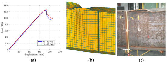
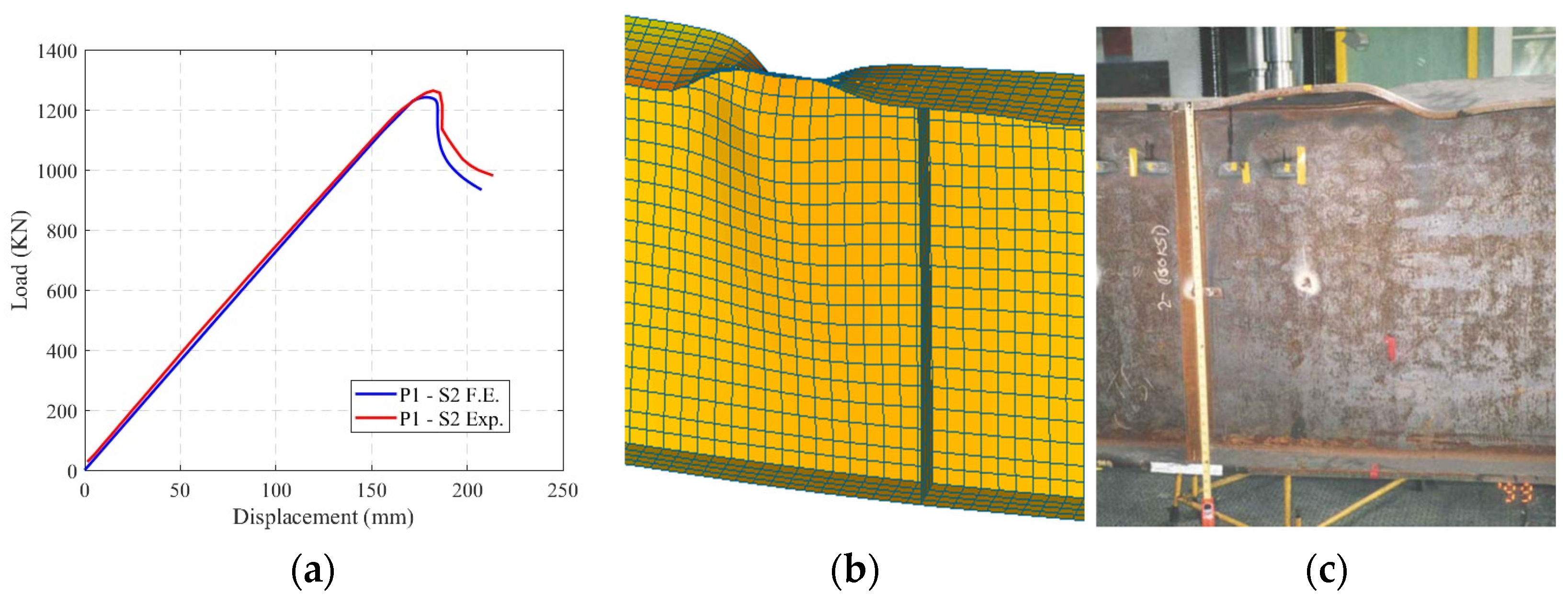
As further evidence, Figure 2a presents examples of typical load–displacement curves, showing good correspondence between numerical and experimental results in terms of peak load, initial stiffness and post-peak behaviour. Additionally, Figure 2b,c illustrate the similarity of failure modes between experiments and simulations. Based on these results, the F.E. models are deemed reliable substitutes for physical testing and were extensively used in the subsequent numerical parametric studies.
Figure 2.
Examples of test vs. F.E. (a) Load–displacement curves, (b) F.E. failure modes, (c) experimental failure modes.
2.5. Parametric Study
Once the F.E. modelling procedure was fully established, a comprehensive parametric study was carried out covering a broad spectrum of I-section geometries. In total, 25 cross-sections were considered. These sections were selected from practical applications to reflect typical constructional detailing encountered in practice, due to the lack of information from the aluminium catalogue for I-bridge sections. Each case included both L.B.A. and G.M.N.I.A. analyses. The studied section heights, h, ranged from 508 to 2540 mm; flange widths, b, from 127 to 304.8 mm; flange thicknesses, tf, from 12.7 to 34.8 mm; and web thicknesses, tw, from 7.9375 to 15.875 mm. Consequently, height-to-width ratios, h/b, ranged from 4 to 8.4; flange slenderness, b/tf, from 6.7 to 13.8; and web slenderness, h/tw, from 37.6 to 194.5. For each cross-section, two aluminium alloy were considered: C.S.A. 6061-T6 (Fy = 240 MPa); C.S.A. 6063-T6 (Fy = 170 MPa). The specimen length equals three times the section height, approximately three half-wave lengths (HWLs), suggested by a study on the local buckling behaviour of Mefande Wack et al. 2025 [17], corresponding to the case HWL = h | L = 3 h | Ampl. = h/200. In total, 600 non-linear F.E. analyses, comprising 300 L.B.A. and 300 G.M.N.I.A., were performed.
3. Effects of Strain Hardening on Aluminium Beams
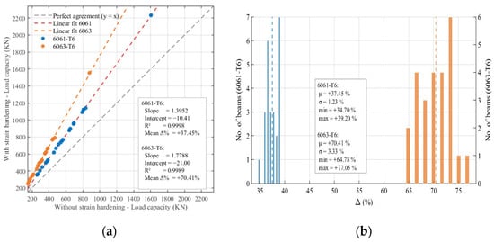
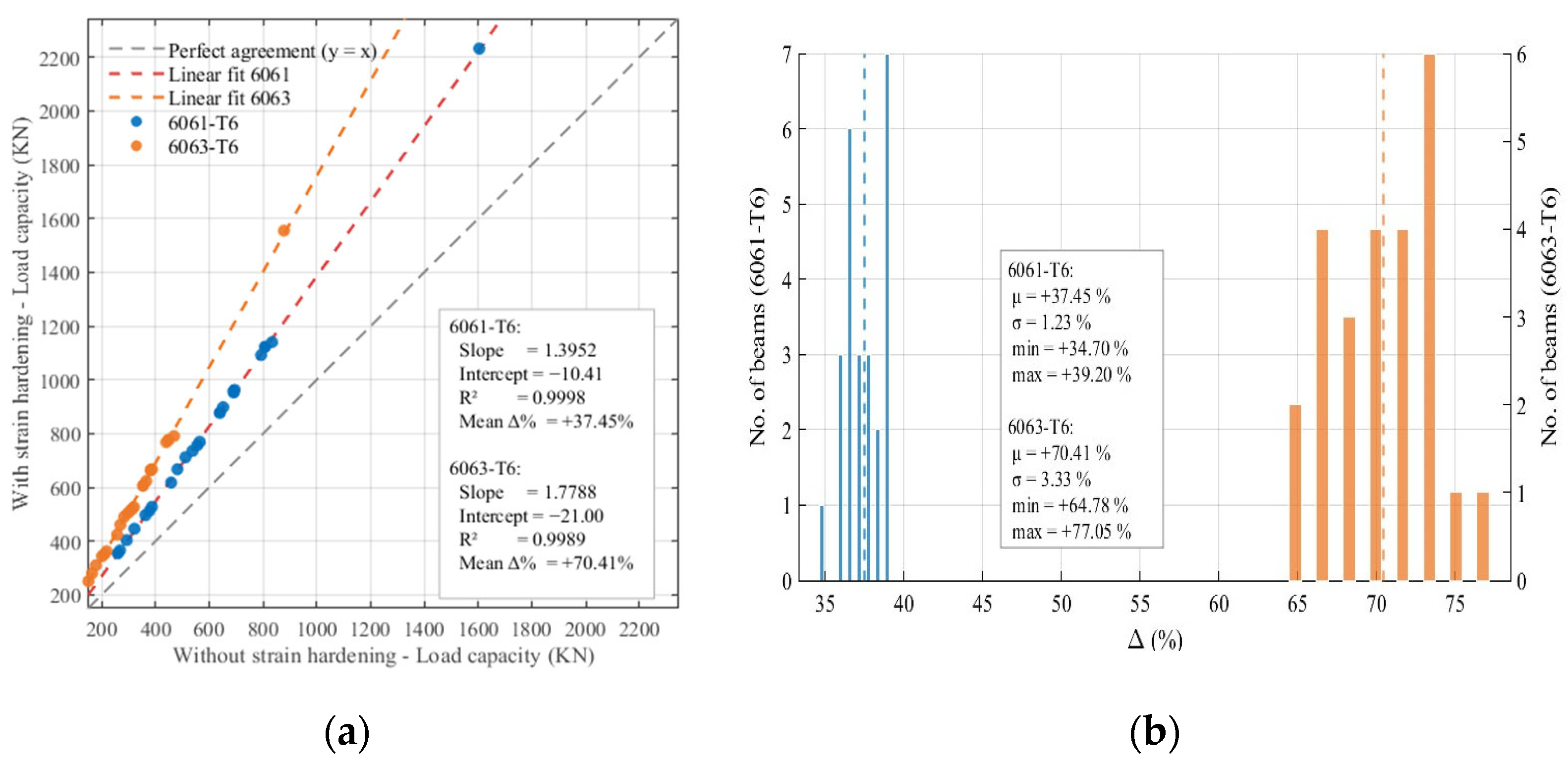
Figure 3 illustrates the influence of strain hardening (SH) through two complementary visualisations. The scatter plot (Figure 3a) compares the ultimate bending capacities obtained with and without strain hardening, where the diagonal line represents perfect agreement. Data points lying above this line indicate an increase in capacity attributable to strain hardening, while the slope of the regression line reflects the proportional amplification of bending resistance. The corresponding histograms (Figure 3b) present the distribution of the relative capacity increase Δ (%), enabling assessment of the magnitude and consistency of the strain hardening effect across all beam configurations.
Figure 3.
Comparison of strength of aluminium beams with and without strain hardening. (a) Ultimate load capacity, (b) histogram of Δ%—blue for 6061-T6 and orange for 6063-T6.
From Figure 3, we observe the SH models producing mean capacity increases of approximately +37% for 6061-T6 and +70% for 6063-T6 relative to the Without-SH condition. The difference between the two alloys reflects their contrasting metallurgical responses: 6063-T6, being more ductile, benefits more from dislocation-based hardening once yielding initiates. Both scatter plots exhibit slopes significantly greater than unity (≈1.40 for 6061-T6 and ≈1.78 for 6063-T6) and R2 ≈ 0.999, indicating that the SH strengthening mechanism is systematic and geometry-independent. The narrow Δ% distributions further show that omitting SH from material modelling leads to a predictable underestimation of cross-section resistance across all beam configurations. For structural applications, this underscores that ignoring SH is only appropriate for highly conservative assessments; otherwise, realistic aluminium beam design must include the post-yield hardening branch to avoid non-negligible unconservative predictions of flexural strength.
4. Effects of Heat-Affected Zones on Welded I-Beams
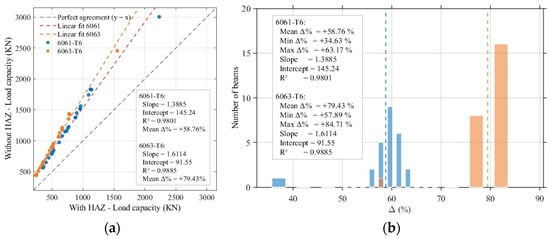
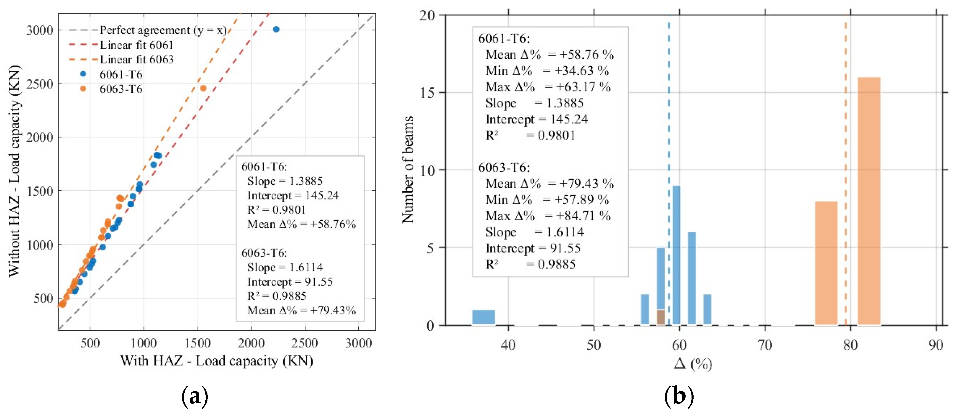
For aluminium beams subjected to bending, the heat-affected zones (HAZs) represent a localised region where thermal cycles from welding or thermal cutting significantly alter the microstructure. These metallurgical modifications significantly reduce local yield strength and stiffness, producing a measurable loss in bending capacity compared with the unaltered base material. In Figure 4, the comparison between the with-HAZ and no-HAZ specimens shows a consistent increase in ultimate load after the removal of HAZ, demonstrating the sensitivity of thin-walled aluminium beams to thermally weakened regions. The scatter plot confirms a strong linear relationship between the two load states (R2 > 0.99 for both alloys), indicating that the “HAZ effect” manifests primarily as a systematic strength reduction (Figure 4a).
Figure 4.
Comparison on strength of aluminium beams with and without HAZ. (a) Ultimate load capacity, (b) histogram of Δ%—blue for 6061-T6 and orange for 6063-T6.
Quantitatively, the Δ% distributions show that removing the HAZ increases bending load capacity by approximately +35% to +63% for 6061-T6 and +77% to +83% for 6063-T6, revealing that 6063 is more sensitive to thermal softening. This suggests that welded or flame-cut connections in 6063-T6 beams require more stringent detailing or post-processing. The comparison further highlights that the width of the HAZ must be properly considered in design, as underestimated HAZ dimensions can lead to unconservative predictions of bending strength. From the present results, the relationship between HAZ width and strength reduction appears linear and predictable, supporting the development of HAZ-dependent reduction factors or localised strengthening strategies (e.g., mechanical cold-working, thermal treatment, or controlled trimming of softened regions). These findings reaffirm that accurate modelling of HAZ effects is essential for aluminium beam reliability in real structural applications.
5. Influence of Residual Stresses for Welded Shapes
Unlike extruded members, welded aluminium beams develop highly localised residual stress (RS) patterns arising from thermal gradients during fusion welding, rapid cooling, and restraint from adjoining material. This residual stress distribution typically consists of tensile stresses at the weld line balanced by compressive regions away from the heat input. The F.E. model used residual stress distribution from laboratory tests on aluminium alloy 6061-T6 plates with an MIG weld technique with tensile residual stress equalling 30% yield strength (RS30) of the materials reported by Zhao et al. [13].
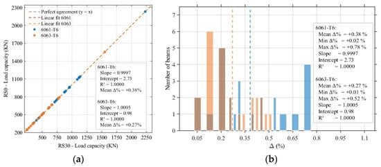
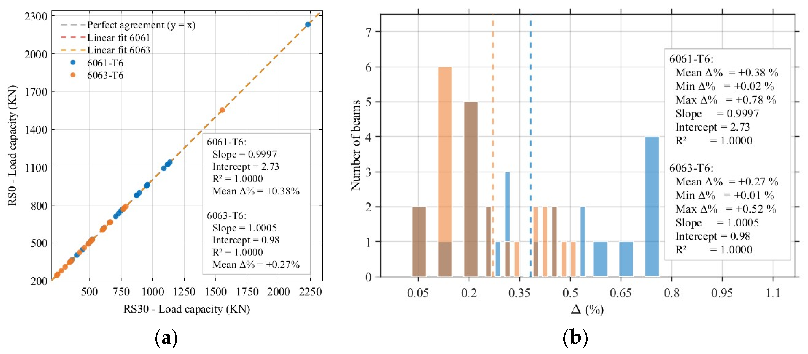
The comparison between the RS30 and without-residual stress (RS0) configurations for all aluminium beam specimens—including both 6061-T6 and 6063-T6—shows that the influence of welding-induced residual stresses on flexural strength is quite small. Across the full dataset, the differences between RS0 and RS30 are almost indistinguishable in the scatter plot (Figure 5a), where all points lie nearly on the perfect-agreement line with only a marginal upward shift. The regression slope is only slightly above unity and the R2 is effectively equal to 1.0, confirming that RS-induced changes in strength are uniform and minimal. This behaviour is also evident in the Δ% histogram (Figure 5b), where all values fall within a narrow band of +0.03% to +0.80%, with negligible dispersion across all the beams. Such consistently small differences indicate that residual stresses do not govern the bending response of these large, slender welded I-sections. Unlike the pronounced effects observed for HAZ softening or strain hardening behaviour, residual stresses affect only a very limited region within the web and do not significantly alter either the global section stiffness or the local buckling behaviour. For slender aluminium bridge beams with deep webs and high slenderness, geometric imperfections and plate slenderness dominate the instability mechanism, rendering the RS effect secondary. Consequently, the explicit modelling of residual stresses may be safely omitted in practical non-linear analysis.
Figure 5.
Comparison on strength of aluminium beams with and without residual stress. (a) Ultimate load capacity, (b) histogram of Δ%—blue for 6061-T6 and orange for 6063-T6.
6. Comparison Between Current Design Rule Predictions and F.E. Results
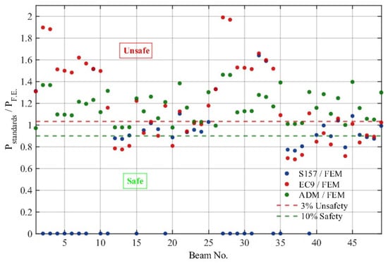
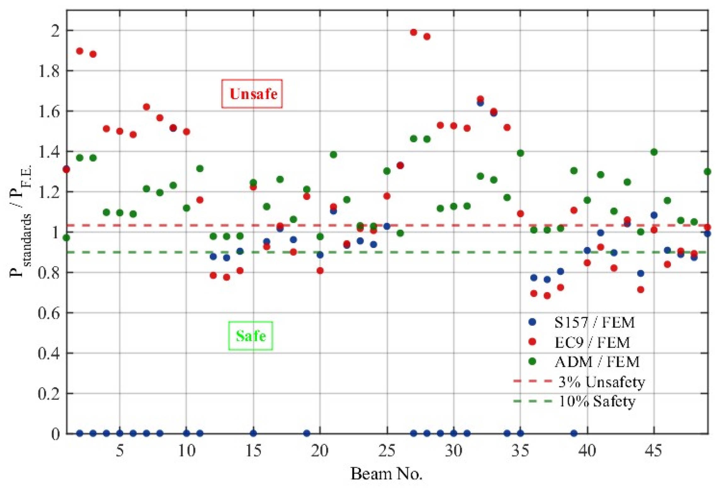
The comparison between the load-carrying predictions of the three aluminium design standards (S157, EC9 and ADM) and the validated F.E. model (with strain hardening, area of HAZ following current designs and tensile residual stresses with 30% yield strength of materials) shows that none of the current provisions fully captures the flexural response of large, welded aluminium I-sections (Figure 6). Although all specimens are nominally classified as Class 3 sections (slender), the associated plate slenderness values (λ) calculated based on section properties—especially most of the web slenderness ranging from 0.76 to 2.39—are far beyond the range implicitly assumed in the development of existing rules. As a result, the standards exhibit markedly different behaviours. S157 is the most restrictive: whenever both the flange and web are Class 3 and λ exceeds its applicability range, the standard does not allow a design bending strength to be calculated. These cases manifest in the scatter plot as zero-capacity points and highlight that S157 is unsuitable for deep, highly slender welded aluminium beams. However, for the calculated beams considered in this study, the results remain relatively conservative and fall within the commonly accepted range of 0.90–1.03 for F.E. predictions.
Figure 6.
Comparison of strength of aluminium 6061-T6 and 6063-T6 I-beams based on current design recommendations and F.E. results.
EC9 produces capacity predictions for all specimens, but with a large scatter and numerous values above the 3% unsafety threshold. The effective-width reduction rules in EC9 are highly sensitive to section slenderness, and for the quite high slenderness encountered here, the assumed post-buckling distribution becomes non-representative of the actual instability modes captured in the FE model. ADM, although generally more consistent, also exhibits a substantial number of unsafe predictions. This trend reflects the fact that ADM—while smoother and less abrupt than those in S157 or EC9—were still calibrated for extruded profiles with moderate depths (typically < 300 mm). When applied to welded bridge-scale I-beams with depths between 500 mm and 2500 mm, the large slenderness ratios cause premature web buckling that none of the standards predict accurately, resulting in systematic overestimation of bending resistance.
Overall, the results confirm that all three standards require refinement before they can be reliably used for large aluminium I-girders. S157 is overly conservative or non-applicable under high slenderness; EC9 becomes inconsistent with the results distributed from conservatively to frequently at extreme unsafety; and ADM still overpredicts capacity for many specimens. These findings indicate a strong need for future research focused on revising slenderness-dependent reduction factors, redefining Class 3 limits for aluminium plates with λ > 0.8, and developing improved post-buckling models calibrated using validated numerical simulations. Such developments are essential to extend the safe and economical design of aluminium bridge girders beyond the dimensional limits of existing standards.
7. Conclusions and Future Work
The parametric study shows that the three examined mechanisms—strain hardening, HAZ softening, and welding-induced residual stress—affect the bending response of welded aluminium I-beams to markedly different degrees. Strain hardening and HAZ softening are dominant, significantly influencing flexural capacity, while residual stresses have a negligible effect, with differences between RS30 and RS0 within a few tenths of a percent. This indicates that bending resistance of deep, slender welded beams is governed mainly by plate slenderness, geometric imperfections, and web-flange interaction rather than residual stresses.
The design standards S157, EC9, and ADM exhibit notable limitations for large bridge-scale aluminium I-beams: S157 is often inapplicable, EC9 shows high scatter with unsafe predictions, and ADM provides the most consistent—though still imperfect—agreement with FE results. These findings suggest that residual stresses can be omitted in numerical models if slightly increased geometric imperfections are used. In contrast, the strong influence of HAZ softening and strain hardening highlights the need for improved material characterisation and modelling of welded regions. The discrepancies with current standards also indicate the need to recalibrate slender-plate resistance models, which were originally developed for smaller extruded sections.
Future work will focus on experimental validation of local buckling in aluminium bridge sections, including web, flange, and interaction effects at welded joints, as well as lateral–torsional buckling in slender, asymmetric configurations. The Overall Interaction Concept (O.I.C.) will also be further developed as a promising approach to improve predictions of buckling behaviour and support more reliable and efficient design of welded aluminium bridges.
Author Contributions
Conceptualization, N.H.D.; methodology, N.H.D. and N.B.; software, N.H.D.; validation, N.H.D.; formal analysis, N.H.D.; investigation, N.H.D.; resources, N.B.; data curation, N.H.D. and K.A.; writing—original draft preparation, N.H.D. and K.A.; writing—review and editing, N.H.D. and K.A.; visualization, N.H.D. and K.A.; supervision, N.B.; project administration, K.A.; funding acquisition, N.B. All authors have read and agreed to the published version of the manuscript.
Funding
The authors gratefully acknowledge the financial supports from the AluQuébec (grant number FT136943), for the Doctoral Program of Higher Education. Thanks are also extended to the Department of Civil Engineering, Laval University for the test conditions and equipment provided. Also, a special thanks to REGAL group for research environment and supporting.
Institutional Review Board Statement
Not applicable.
Informed Consent Statement
Not applicable.
Data Availability Statement
The data presented in this study are available within the article.
Conflicts of Interest
The authors declare no conflict of interest.
References
- Mazzolani, F.M. Aluminium Alloy Structures, 2nd ed.; E & FN Spon: London, UK, 1995. [Google Scholar]
- ECCS. European Recommendations for Aluminium Alloy Structures; European Convention for Constructional Steelwork: Brussels, Belgium, 1978. [Google Scholar]
- The Aluminum Association. Aluminum Design Manual; The Aluminum Association: Washington, DC, USA, 2015. [Google Scholar]
- EN 1999-1-1; Eurocode 9–Design of Aluminium Structures–Part 1-1: General Structural Rules. CEN: Brussels, Belgium, 2007.
- CSA S7:23; Pedestrian, Cycling, and Multiuse Bridge Design Guideline. CSA: Mississauga, ON, Canada, 2023.
- Dahboul, S.; Coderre, T.; Liya, L.; Boissonnade, N. Behaviour and Design of I-Shaped Aluminium Sections. Eng. Proc. 2023, 43, 35. [Google Scholar] [CrossRef] [Scilit]
- Kissell, J.R.; Ferry, R.L. Aluminum Structures: A Guide to Their Specifications and Design, 2nd ed.; John Wiley & Sons: New York, NY, USA, 2002. [Google Scholar]
- EN 755-9; Aluminium and Aluminium Alloys—Extruded Rod/Bar, Tube and Profiles—Part 9: Profiles, Tolerances on Dimensions and Form. European Committee for Standardization (CEN): Brussels, Belgium, 2016.
- AASHTO. AASHTO LRFD Bridge Design Specifications, 9th ed.; American Association of State Highway and Transportation Officials: Washington, DC, USA, 2020. [Google Scholar]
- Bureau d’Etudes Greisch. FINELG—Non-Linear Finite Element Analysis Program, User’s Manual, Version 9.0; Department ArGEnCo, University of Liège & Bureau Greisch: Liège, Belgium, 1989. [Google Scholar]
- Zha, Y.; Moan, T. Ultimate strength of stiffened aluminium panels with predominantly torsional failure modes. Thin-Walled Struct. 2001, 39, 631–648. [Google Scholar] [CrossRef] [Scilit]
- Rigo, P.; Sarghiuta, R.; Estefen, S.; Lehmann, E.; Otelea, S.C.; Pasqualino, I.; Simonsen, B.C.; Wan, Z.; Yao, T. Sensitivity analysis on ultimate strength of aluminium stiffened panels. Mar. Struct. 2003, 16, 437–468. [Google Scholar] [CrossRef] [Scilit]
- Shusen, Z.; Yanmin, L.; Rui, H.; Zhanshu, H. Numerical study of the residual stress and welding deformation of mid-thick plate of AA6061-T6 in the multi-pass MIG welding process. J. Mech. Sci. Technol. 2021, 35, 4931–4942. [Google Scholar] [CrossRef] [Scilit]
- Matusiak, M. Strength and Ductility of Welded Structures in Aluminium Alloys. Ph.D. Thesis, Norwegian University of Science and Technology (NTNU), Trondheim, Norway, 1999. [Google Scholar]
- Kristensen, O.H.H.; Moan, T. Ultimate strength of aluminium plates under biaxial loading. In Proceedings of the Fifth International Conference on Fast Sea Transportation (FAST ‘99); Society of Naval Architects and Marine Engineers: New York, NY, USA, 1999. [Google Scholar]
- Said, S.E.; Richard, S. Flexural Strength and Ductility of Highway Bridge I-Girders Fabricated from HPS-100W Steel. Ph.D. Thesis, Lehigh University, Bethlehem, PA, USA, 2004. [Google Scholar]
- Mefande Wack, M.C.; Chhoeng, O.; Tremblay, R.; Boissonnade, N. On the definition of geometric imperfections in the F.E. modelling of local buckling in hot-rolled channel sections. In Proceedings of the Annual Stability Conference Structural Stability Research Council, SSRC 2025, Louisville, KY, USA, 1–4 April 2025. [Google Scholar]

Disclaimer/Publisher’s Note: The statements, opinions and data contained in all publications are solely those of the individual author(s) and contributor(s) and not of MDPI and/or the editor(s). MDPI and/or the editor(s) disclaim responsibility for any injury to people or property resulting from any ideas, methods, instructions or products referred to in the content. |
© 2026 by the authors. Licensee MDPI, Basel, Switzerland. This article is an open access article distributed under the terms and conditions of the Creative Commons Attribution (CC BY) license.