


Abstract
Aluminum hollow structural sections are increasingly used in construction due to their high strength-to-weight ratio, corrosion resistance, formability, and compatibility with advanced manufacturing processes that enable optimized geometries. While the local buckling behavior of conventional Square Hollow Sections (SHSs) and Circular Hollow Sections (CHSs) has been extensively studied, limited research exists on Polygonal Hollow Sections (PHSs), which geometrically bridge SHSs and CHSs and are commonly used in applications such as sign structures, lighting poles, and transmission towers. This study presents a comprehensive numerical investigation of local buckling behavior and ultimate compressive resistance of aluminum CHSs, polygonal, and SHSs. A wide parametric study covering multiple aluminum alloys, dimensions, and side numbers is conducted. The results demonstrate a progressive transition in buckling behavior from plate-dominated response in SHSs to shell-dominated response in CHSs, with polygonal sections showing intermediate behavior. Increasing the number of polygon sides enhances compressive resistance and reduces sensitivity to slenderness. Comparisons with current design standards highlight gaps in predicting the resistance of polygonal sections, particularly due to the absence of dedicated classification rules and limited consideration of strain hardening effects. The findings support the development of improved design approaches for closed aluminum sections.
1. Introduction
According to current construction trends, aluminum has become a widely used material due to its numerous benefits as a structural material, i.e., high strength-to-weight ratio, ease of fabrication, high degree of workability, considerable ductility, excellent thermal conductivity, high corrosion resistance and attractive appearance at their natural finish. For this reason, 25% of the global aluminum production is currently used in the construction sector [1]. In addition, the aluminum manufacturing processes allow the generation of irregular sections using processes such as extrusion [1] and 3D printing manufacturing techniques such as WAAM (Wire Arc Additive Manufacturing) or powder bed fusion (PBF) [2]. These features make aluminum an attractive and promising material for optimizing structural sections and increasing efficiency in material consumption.
Standardized sections like Square Hollow Sections (SHSs) and Circular Hollow Sections (CHSs) have been used for several aluminum alloys and manufacturing processes to develop structural solutions in construction. In the past, these sections have been investigated to understand the plate and shell buckling behavior under compression loads for a wide variety of aluminum alloys and width-to-thickness ratios for both SHSs [2,3,4,5,6,7,8] and CHSs [9,10,11,12].
In contrast, Polygonal Hollow Sections (PHSs), which occupy an intermediate position between SHSs and CHSs, are used in many structures, like overhead road sign members, light posts, power transmission poles, etc. [13]. However, the study and understanding of the local buckling and ultimate strength resistance of aluminum polygonal sections are still lacking. Current international standards like EC9 [14] and CSA S157 [15] do not provide specific formulas for the local buckling resistance and section cross-section classification for these elements.
The local buckling resistance in Polygonal Hollow Sections has been studied using other metallic materials such as carbon steel, high-strength steel and stainless steel. Bulson [16] performed compression tests on short polygonal columns with a different number of sides between 4 and 40 to determine the ultimate compression load for different slenderness ratios. It was found that the ultimate load increases with the number of corners. Migita and Fukumoto [17] developed different analytical and experimental studies for polygonal thin-walled steel sections considering different aspect ratios, bent angles, number of sides and buckling modes. Gadot et al. [13] studied the local buckling behavior of different polygonal steel sections under concentric compressive loads (eight-sided, twelve-sided and sixteen-sided) with different slenderness ratios. Initial imperfections were also measured. Additionally, an equation was proposed to determine ultimate stress based on Loov’s design equation. Dalia et al. [18] performed a parametric finite element (FE) analysis on different polygonal steel sections (eight-sided, twelve-sided and sixteen-sided) for different slenderness ratios under pure compression, pure bending and combined load cases. In this study a comparison was performed between the numerical results and different standards (EC3, AASHTO, ASCE), concluding that EC3 and AASHTO provide accurate equations. Kabanda and MacDougall [19] study the bending capacity for RHS and Polygonal Hollow Sections, obtaining a higher bending capacity and four times more rotational capacity for polygonal sections than for standard RHS.
Despite the ease of manufacture and its benefits as a structural material, especially for irregular sections, local buckling of polygonal cross-sections made of aluminum alloys has not been studied exhaustively. Yokoya et al. [20], Baleh et al. [21] and Rossi et al. [22] studied the post-buckling and collapse behavior and the energy absorption capacity under impact loads for different aluminum polygonal sections.
As seen above, there are few studies concerning the local buckling behavior of PHS made of aluminum alloys. Therefore, in this paper a numerical study is conducted to study the structural response of PHS aluminum sections subjected to compression loads with the objective of understanding the local buckling influence on the multi-sided elements and analyzing the transition between plate buckling and shell buckling.
Section 2 describes the finite element model with the parametric study and the initial imperfection selection. Section 3 presents the numerical results for the different aluminum alloys and PHSs studied, and different comparisons between slenderness and relations are developed, showing an increase in the ultimate compression resistance among the cross sections considered with more sides.
2. Numerical Analysis
2.1. Finite Element Modeling
A numerical model is developed employing the nonlinear FE software ABAQUS 2025 [23] to study the compression resistance for different polygonal sections, with the aim of understanding the local buckling progression from SHSs to CHSs stub columns. The modeling process considers the evaluation of the elastic buckling load associated with the first eigenmode through the development of a Linear Buckling Analysis (LBA). Then, a Geometrically and Materially Nonlinear with Imperfections Analysis (GMNIA) is used to determine the ultimate compression load, considering the shape of the first buckling mode, to evaluate the ultimate compression resistance and the post-buckling behavior for the different polygonal sections.
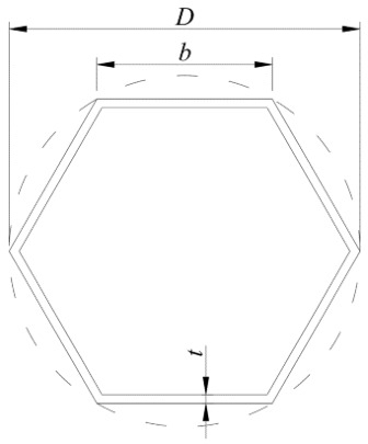
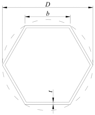
The element size has been considered by developing a mesh sensitivity study to ensure the model precision to represent properly the local buckling without an excessive computational consumption. The adopted mesh size is equivalent to Nsidesb/100, where Nsides is the number of sides and b is the length of the cross-section side (See Figure 1), while also ensuring at least eight shell elements per cross-section side.
Figure 1.
Geometry and notation for regular polygon sections.
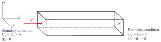
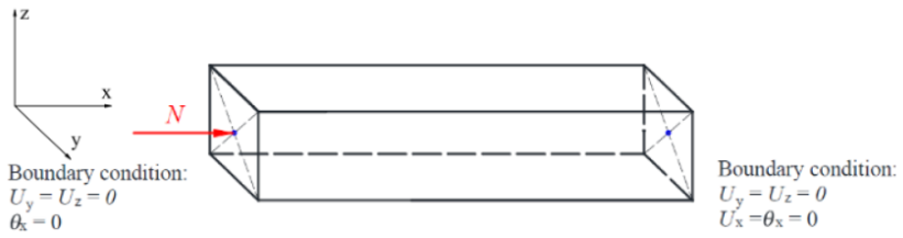
The boundary conditions in the numerical models are based on a simply supported fork-type condition. The edges are restricted to rotations and out-of-plane displacements, i.e., Ux = Uy = Uz = θx = 0 for the left corner and Uy = Uz = θx = 0 at the right corner, as shown in Figure 2. On the other hand, the compressive load is applied at a reference point located at the centroid of the section and is coupled to the end section with a rigid body constraint, ensuring uniform load transfer around the entire cross-section.
Figure 2.
Boundary conditions in numerical models.
The material definition considers the engineering stress–strain curve, converting into true stress and logarithmic plastic strain [23]. The material behavior of aluminum alloys was characterized using the Ramberg–Osgood equation, considering the strain hardening effects and adapted for nonlinear analysis in finite element modeling. The numerical models consider four aluminum alloys: 6061-T6, 6063-T6, 6082-T6 and 5356. Table 1 shows the mechanical properties considered and the calibrated parameters used to represent the nonlinear materials.
Table 1.
Mechanical properties of aluminum alloys.
These materials enable a meaningful comparison of the structural response across different aluminum alloy series. In particular, 6000-series alloys are widely used in structural applications, whereas the 5356 alloy is predominantly employed in WAAM applications, thereby allowing the assessment of both conventional and additively manufactured material behaviors.
2.2. Parametric Study
A parametric study is performed to determine the ultimate compressive resistance of different aluminum SHSs, PHSs and CHSs. The parameters were selected from commercial CHS databases. Figure 2 shows how the different hollow sections were generated based on the external circumference for regular PHSs, where D is the external diameter of the section, t is the section thickness and b is the length of the section side. It is important to note that these hollow sections do not consider any corner filet radius.
According to the notation presented in Figure 2, four different types of PHSs with 4, 6, 8 and 10 sides and CHSs are studied, with a diameter D range from 25 to 160 mm, a thickness t range from 1.20 mm to 8.00 mm and a slenderness ratio D/t range from 12.00 to 106.67.
The parametric study considers the analysis of 180 models to develop the initial imperfection study explained in the next section and 525 models to determine the ultimate compression load in the GMNIA analyses for the different PHSs and CHSs studied.
2.3. Initial Imperfections Influence
The initial imperfection amplitude was selected according to Equations (1)–(4), selected from different authors that developed studies on the initial imperfection influence on CHSs based on parameters related to geometry,
where r is the mid-thickness radius for the outer circumference of the polygonal sections.
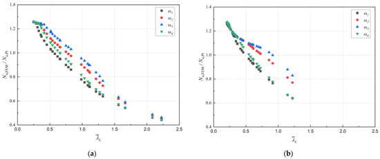
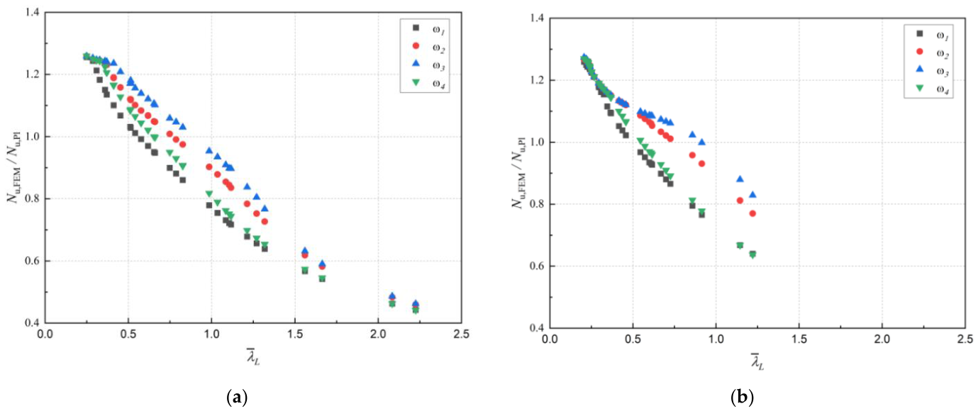
The initial imperfection study is developed for the aluminum alloy 6061-T6 with the cross-sections corresponding to two different PHSs (four sides and eight sides). Figure 3a,b shows the influence of the initial imperfection on the ultimate compression resistance for the selected cross-sections.
Figure 3.
Comparison of compression resistance for different initial imperfections: (a) 4 sides, (b) 8 sides.
The compression resistance is compared against the normalized slenderness (), defined as follows:
where is the elastic critical load obtained from LBA and carried out in ABAQUS 2025 [23], (taken as the 0.2% proof stress) is the material yield strength, and A is the cross-sectional area. The vertical axis corresponds to the normalized ultimate resistance, expressed as , where considers the ultimate resistance from the GMNIA.
Figure 3a,b as expected, presents a diverse behavior in the compression resistance for the analyzed types of initial imperfection. and show an increase in compressive strength for values of > 0.5. On the other hand, the imperfections and exhibit very similar values and show a gradual decrease as increases.
Thus, the initial imperfection associated with is selected, as it provides more uniform ultimate compression load predictions across the range of normalized slenderness values for the considered sections.
3. SHSs’, PHSs’ and CHSs’ Ultimate Resistance
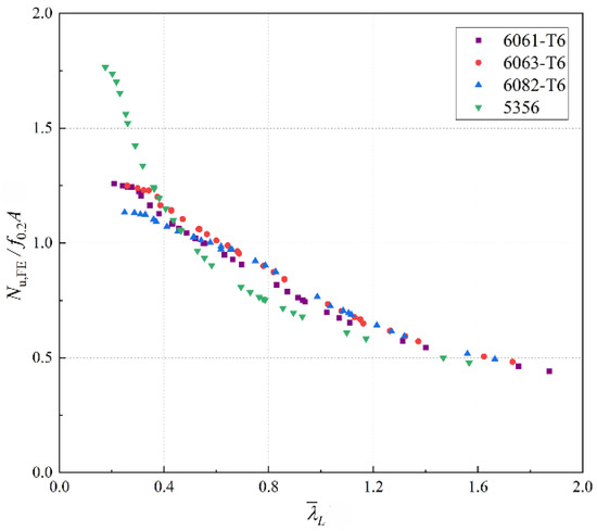
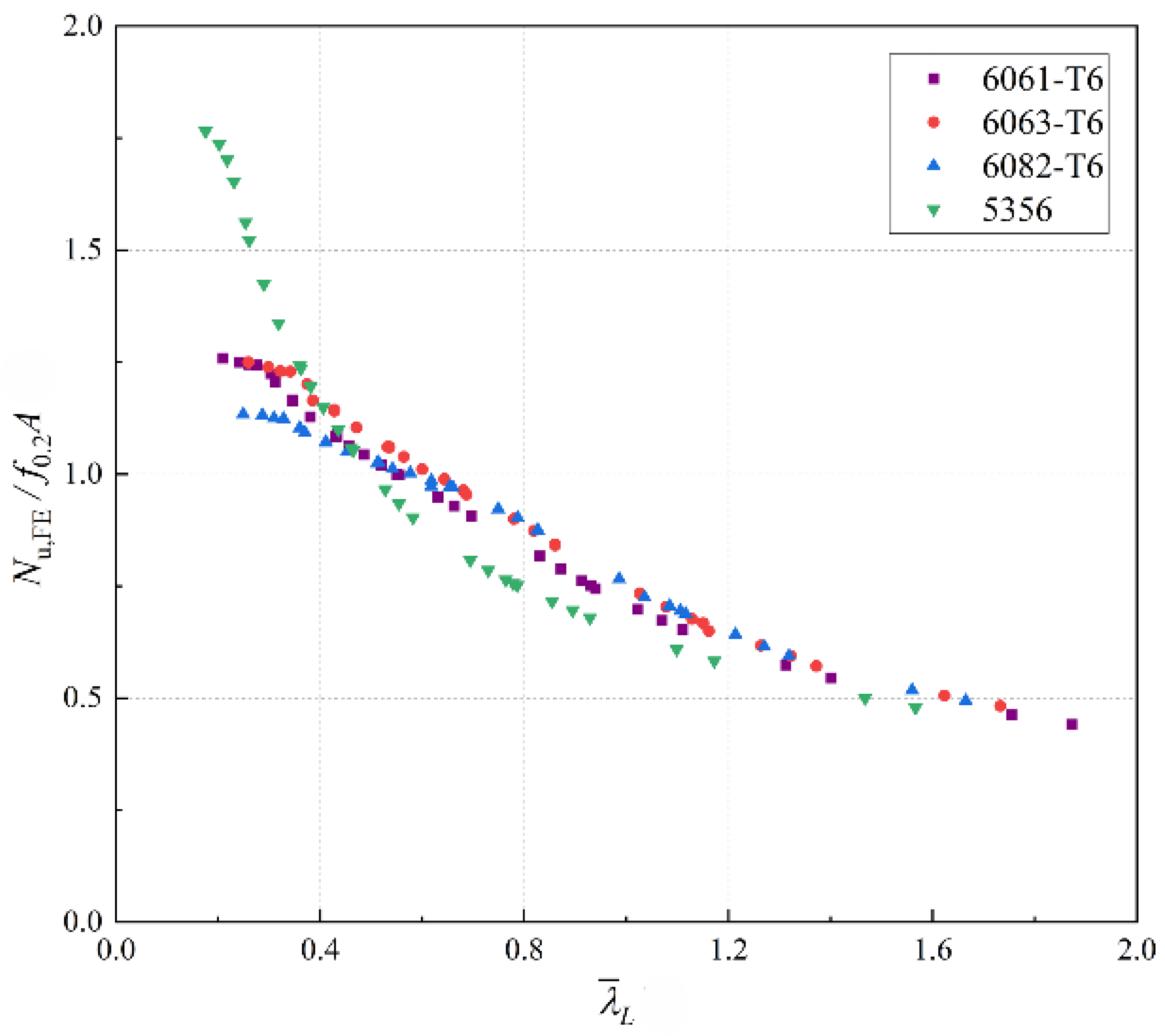
The results of the parametric study are presented in this section for the different PHSs and CHSs configurations analyzed. Figure 4 presents the normalized compressive resistance of eight-sided PHSs plotted against normalized slenderness for the four different alloys considered in this study.
Figure 4.
Comparison of cross-section resistance for different alloys—8-sided PHSs.
Although the normalized slenderness of the sections is influenced by variations in yield strength among the alloys, the resistance curves exhibit a similar overall trend. This behavior allows a relatively uniform response to be observed for the 6000-series alloys. In contrast, for the 5356 alloy, slightly lower compressive resistance values are obtained for > 0.5 when compared to the 6000-series alloys. However, for < 0.5, the influence of strain hardening becomes dominant, significantly exceeding the resistance levels observed for the 6000-series alloys.
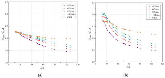
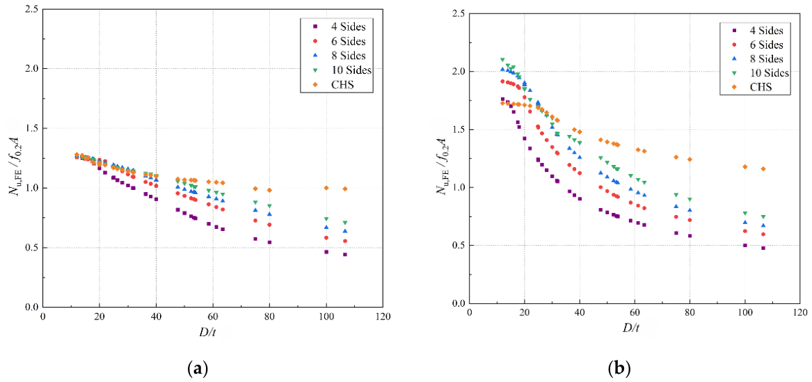
Figure 5a,b show the normalized ultimate compressive load as a function of the width-to-thickness ratio (D/t) for each polygonal section, corresponding to the 6061-T6 and 5356 alloys, respectively. As expected, the ultimate compressive resistance decreases as the D/t ratio increases.
Figure 5.
Comparison of cross-section resistance for different numbers of sides with D/t ratio: (a) Alloy 6061-T6; (b) Alloy 5356.
Furthermore, the influence of the number of sides indicates that an increase in the number of sides of the cross-section leads to a higher compressive resistance due to the stiffening effect of the section, with the maximum compressive resistance achieved by CHSs. Additionally, for larger D/t ratios, the influence of the number of sides becomes more pronounced, resulting in higher compressive resistance for CHSs and PHSs with more sides.
Moreover, a significant influence of the strain-hardening effect on the ultimate compressive resistance is observed between the 6061-T6 and 5356 alloys, where strain hardening in the 5356 alloy increases the compressive resistance up to 2.2 times the plastic resistance of the section. An exception is observed for CHSs, which only reach a value of 1.70 for the most compact sections.
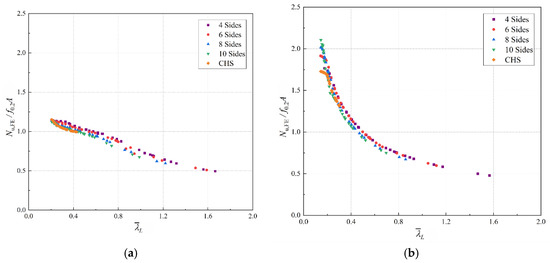
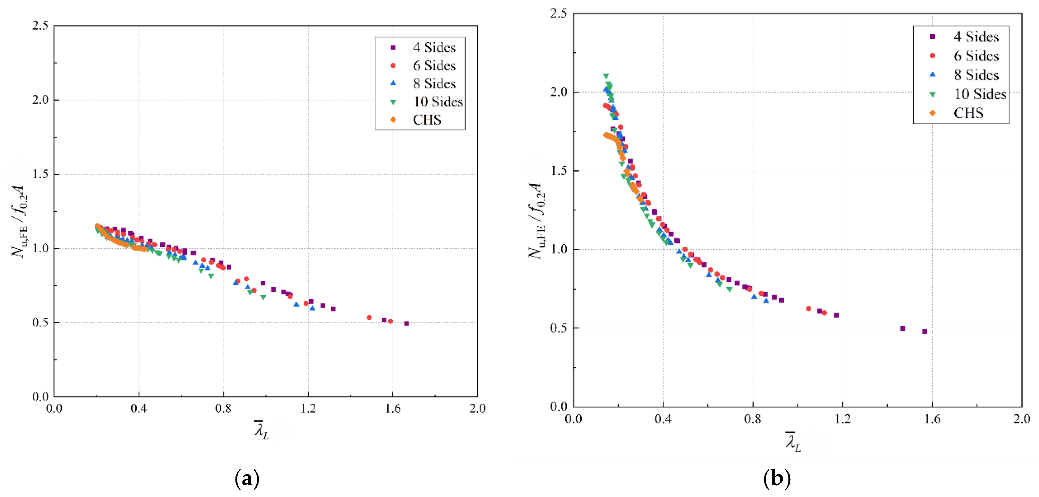
Figure 6 compares the ultimate compressive resistance with the slenderness-based cross-section resistance of the PHSs and CHSs, determined according to Equation 5, previously described, for the 6061-T6 and 5356 alloys.
Figure 6.
Comparison of cross-section resistance for different numbers of sides normalized slenderness: (a) alloy 6082-T6; (b) alloy 5356.
Figure 6a,b indicate that an increase in the number of sides of the cross-section leads to a reduction in normalized slenderness, decreasing from maximum values of = 1.55 for four-sided sections to 0.33 for CHSs. Additionally, similar ultimate compressive resistance values are obtained for both alloys, indicating that the slenderness-based section classification allows reliable prediction of cross-sectional resistance for sections with different numbers of sides.
Regarding the strain-hardening effect observed for the different alloys, the 6061-T6 alloy reaches a maximum value of approximately 1.15 times the plastic resistance, whereas the 5356 alloy achieves values of up to 2.2 times the plastic resistance of the section. This highlights the importance of strain hardening in this alloy and its significant contribution to strength enhancement, particularly for slenderness ratios lower than < 0.50.
4. Comparison Between EC9 and CSA S157
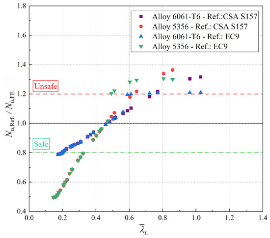
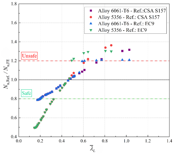
The compression resistance from FE models for the PHS are compared with the aluminum design codes EC9 and CSA S157, as shown in Figure 7, where the NU,ref./NU,FE ratio provides the comparison between the reference codes and the numerical results.
Figure 7.
Design codes vs. numerical results for 8-sided PHSs.
The compressive resistance of the studied eight-sided PHSs within the compact and slender ranges allows identifying that the two considered alloys exhibit a structural behavior strongly influenced by material properties. Furthermore, in the slender section range ( < 0.50), the compressive resistance achieved by the sections under the studied conditions is overestimated, particularly when applying the provisions of the CSA S157 code. Within this range ( < 0.50) the compressive resistance for EC9 and CSA S157 the results superimposed each other.
For compact sections, it is important to highlight the effect of strain hardening, where the compressive resistance is underestimated, leading to strength ratios of 0.80 and 0.50 for the 6061-T6 and 5356 alloys, respectively.
5. Conclusions
The study has shown the progression of the normalized slenderness from Square Hollow Sections (SHSs) through polygonal multi-sided sections to circular hollow sections, highlighting the increase in section efficiency from four-sided PHSs to CHSs.
The numerical results for the four studied alloys show an increase in compressive resistance as the number of sides increases. At the same time, this increase in the number of sides enhances the compressive resistance with an increasing D/t ratio. Comparisons based on normalized slenderness were carried out, demonstrating that this type of classification allows for a homogeneous classification of sections, regardless of the number of sides for PHSs and CHSs.
It is observed that alloy 5356 has great potential for the development of structures manufactured by WAAM, where it is important to consider the influence of the mechanical properties in order to avoid underestimating the compression resistance when compared to conventional 6000-series alloys.
Comparisons with aluminum design codes were carried out and revealed a lack of accuracy in section classification, leading to overestimations for slender sections and inaccurate predictions within the compact range. These approaches neglect the strain hardening effect provided by aluminum materials. It is observed that Eurocode 9 (EC9) reaches resistance estimations that are closer to the FE-obtained section strength.
This study is part of an experimental program on WAAM aluminum polygonal sections, and the presented results will be validated with the experimental data. In addition, future studies will focus on proposing polygonal cross-section classification and compression resistance approaches. Furthermore, a lack of consideration in current design codes for complex geometries is identified, which, with the introduction of new manufacturing processes, can be developed. This study highlights the importance of improving the understanding of WAAM-produced sections.
Author Contributions
Conceptualization and methodology J.D.O. and L.L.; software, J.D.O.; validation, J.D.O., L.L. and C.G.; formal analysis, J.D.O.; investigation, J.D.O.; resources, L.L. and C.G.; data curation, J.D.O.; writing—original draft preparation, J.D.O.; writing—review and editing, J.D.O., L.L. and C.G.; visualization, J.D.O.; supervision, L.L. and C.G.; project administration, L.L.; funding acquisition, L.L. All authors have read and agreed to the published version of the manuscript.
Funding
The authors acknowledge the financial support provided by the Fonds de recherche du Québec–Nature et technologies (FRQNT). Their support is sincerely appreciated and contributed to the completion of this research.
Institutional Review Board Statement
Not applicable.
Informed Consent Statement
Not applicable.
Data Availability Statement
Data will be made available on request.
Conflicts of Interest
The authors declare no conflict of interest.
References
- Georgantzia, E.; Gkantou, M.; Kamaris, G.S. Aluminium alloys as structural material: A review of research. Eng. Struct. 2021, 227, 111372. [Google Scholar] [CrossRef] [Scilit]
- Zhang, R.; Amraei, M.; Piili, H.; Gardner, L. Testing of additively manufactured aluminium material and cross-sections in compression. Eng. Struct. 2025, 341, 120798. [Google Scholar] [CrossRef] [Scilit]
- Faella, C.; Mazzolani, F.M.; Piluso, V.; Rizzano, G. Local Buckling of Aluminum Members: Testing and Classification. J. Struct. Eng. 2000, 126, 353–360. [Google Scholar] [CrossRef] [Scilit]
- Feng, R.; Zhu, W.; Wan, H.; Chen, A.; Chen, Y. Tests of perforated aluminium alloy SHSs and RHSs under axial compression. Thin-Walled Struct. 2018, 130, 194–212. [Google Scholar] [CrossRef] [Scilit]
- Feng, R.; Liu, J. Numerical investigation and design of perforated aluminium alloy SHS and RHS columns. Eng. Struct. 2019, 199, 109591. [Google Scholar] [CrossRef] [Scilit]
- Hu, Y.; Rong, B.; Zhang, R.; Zhang, Y.; Zhang, S. Study of buckling behavior for 7A04-T6 aluminum alloy rectangular hollow columns. Thin-Walled Struct. 2021, 169, 108410. [Google Scholar] [CrossRef] [Scilit]
- Li, B.; Wang, Y.; Zhang, Y.; Yuan, H.; Zhi, X.; Baniotopoulos, C.C. Flexural behaviour of 7A04-T6 high-strength aluminium alloy SHS and RHS beams under moment gradient. Eng. Struct. 2022, 259, 114138. [Google Scholar] [CrossRef] [Scilit]
- Bock, M.; Theofanous, M.; Dirar, S.; Lipitkas, N. Aluminium SHS and RHS subjected to biaxial bending: Experimental testing, modelling and design recommendations. Eng. Struct. 2021, 227, 111468. [Google Scholar] [CrossRef] [Scilit]
- Zhu, J.-H.; Young, B. Aluminum alloy circular hollow section beam-columns. Thin-Walled Struct. 2006, 44, 131–140. [Google Scholar] [CrossRef] [Scilit]
- Zhu, J.-H.; Young, B. Numerical investigation and design of aluminum alloy circular hollow section columns. Thin-Walled Struct. 2008, 46, 1437–1449. [Google Scholar] [CrossRef] [Scilit]
- Rong, B.; Zhang, Y.; Zhang, S.; Li, Z. Experiment and numerical investigation on the buckling behavior of 7A04-T6 aluminum alloy columns under eccentric load. J. Build. Eng. 2022, 45, 103625. [Google Scholar] [CrossRef] [Scilit]
- Li, L.; Dahboul, S.; Verma, P.; Dey, P.; Fafard, M.; Boissonnade, N. O.I.C.-Based Design of Aluminum Circular Hollow Sections under Compression or Pure Bending. Eng. Proc. 2023, 43, 31. [Google Scholar] [CrossRef] [Scilit]
- Godat, A.; Legeron, F.; Bazonga, D. Stability investigation of local buckling behavior of tubular polygon columns under concentric compression. Thin-Walled Struct. 2012, 53, 131–140. [Google Scholar] [CrossRef] [Scilit]
- BS EN 1999-1-1:2007; Eurocode 9 (EC9): Design of Aluminium Structures. Part 1-1: General Structural Rules—General Structural Rules and Rules for Buildings. European Committee for Standardization (CEN): Brussels, Belgium, 2022.
- CSA S157-17; Strength Design in Aluminum. Canadian Standards Association: Toronto, ON, Canada, 2017.
- Bulson, P.S. The strength of thin-walled tubes formed from flat elements. Int. J. Mech. Sci. 1969, 11, 613–620. [Google Scholar] [CrossRef] [Scilit]
- Migita, Y.; Fukumoto, Y. Local buckling behaviour of polygonal sections. J. Constr. Steel Res. 1997, 41, 221–233. [Google Scholar] [CrossRef] [Scilit]
- Dalia, Z.M.; Bhowmick, A.K.; Grondin, G.Y. Local buckling of multi-sided steel tube sections under axial compression and bending. J. Constr. Steel Res. 2021, 186, 106909. [Google Scholar] [CrossRef] [Scilit]
- Kabanda, J.S.; MacDougall. Comparison of the moment rotation capacities of rectangular and polygonal hollow sections. J. Constr. Steel Res. 2017, 137, 66–76. [Google Scholar] [CrossRef] [Scilit]
- Yokoya, K.; Miyazaki, M.; Tojo, Y.; Yamashita, M. Deformation behavior of axially compressed aluminum polygonal tube. Procedia Eng. 2017, 207, 251–256. [Google Scholar] [CrossRef] [Scilit]
- Baleh, R.; Abdul, A.; Menouer, A.; Razafindramary, D. New experimental investigation of non-conventional dynamic biaxial plastic buckling of square aluminum tubular structures. Int. J. Impact Eng. 2018, 122, 333–345. [Google Scholar] [CrossRef] [Scilit]
- Rossi, A.; Fawaz, Z.; Behdinan, K. Numerical simulation of the axial collapse of thin-walled polygonal section tubes. Thin-Walled Struct. 2005, 43, 1646–1661. [Google Scholar] [CrossRef] [Scilit]
- ABAQUS 2025 Documentation; Dassault Systèmes Simulia Corp.: Providence, RI, USA, 2025.

Disclaimer/Publisher’s Note: The statements, opinions and data contained in all publications are solely those of the individual author(s) and contributor(s) and not of MDPI and/or the editor(s). MDPI and/or the editor(s) disclaim responsibility for any injury to people or property resulting from any ideas, methods, instructions or products referred to in the content. |
© 2026 by the authors. Licensee MDPI, Basel, Switzerland. This article is an open access article distributed under the terms and conditions of the Creative Commons Attribution (CC BY) license.