Proceeding Paper

Improvement of Joint Strength in Resistance Spot-Welded Joints of Steel/Aluminum Alloy Dissimilar Materials by Using Interface Shape Control †
1
Department of Mechanical Engineering, Faculty of Engineering, Osaka Institute of Technology, 5-16-1 Omiya Asahi-ku, Osaka 535-8585, Japan
2
Department of Mechanical Engineering, Graduate School Engineering, Osaka Institute of Technology, 5-16-1 Omiya Asahi-ku, Osaka 535-8585, Japan
3
Kobe Steel, Ltd., 100-1 Miyamae, Fujisawa 251-8551, Japan
*
Author to whom correspondence should be addressed.
Presented at the 16th International Aluminium Conference (INALCO 2026), Trondheim, Norway, 10–12 June 2026.
Eng. Proc. 2026, 151(1), 17; https://doi.org/10.3390/engproc2026151017
Published: 29 July 2026
(This article belongs to the Proceedings of The 16th International Aluminium Conference)

Abstract

In recent years, the automotive industry has increasingly adopted aluminum alloys in vehicle bodies to improve fuel efficiency. However, it is known that applying resistance spot welding—widely used in automotive production lines—to join steel and aluminum alloys results in the formation of brittle intermetallic compounds at the joint interface, leading to reduced joint strength and increased variability. In this study, the anchor effect—defined as mechanical interlocking at the interface—was examined, and the effect of introducing a rectangular interface on tensile shear strength (TSS) was investigated. The rectangular interface was formed by pre-machining a groove on the steel sheet prior to welding. The effect of the rectangular interface on TSS was examined by comparing joints with and without the interface. The results showed that TSS increased in joints with the rectangular interface. Furthermore, TSS was influenced by the groove geometry, as variations in groove depth and width resulted in changes in TSS. These results indicate that appropriate control of the interface geometry can effectively enhance joint strength.

1. Introduction

In recent years, increasing environmental concerns have driven the automotive industry to adopt multi-material structures, particularly those combining steel and aluminum alloys [1]. This approach enables significant reductions in vehicle weight, thereby contributing to enhanced fuel efficiency and decreased emissions [2,3]. Therefore, when resistance spot welding (RSW), a widely used joining method in automotive manufacturing, is applied to dissimilar materials composed of steel and aluminum alloys, joints are formed through the formation of an intermetallic compound (IMC) layer at the interface [4,5,6]. On the other hand, it is well established that excessive growth of the IMC layer degrades joint strength [7]. In resistance spot-welded joints, peel strength and shear strength are commonly used to evaluate joint strength. A previous study focused on the shape of the joint interface, reporting that forming a rectangular interface alters the orientation of the IMC layer, thereby increasing peel strength [8].
However, the effect of rectangular interfaces on tensile shear strength (TSS) remains unclear. In addition, it is expected that the formation of a rectangular interface could improve TSS through the anchoring effect in the shear direction. Therefore, this study investigates the improvement of TSS in joints with rectangular interfaces, as well as the relationship between interface geometry and the anchoring effect, which arises from mechanical interlocking at the interface.

2. Materials and Methods

2.1. Materials and Welding Conditions

The materials used were 980 MPa-class steel sheets (1.2 mm thick) and A6061-T6 sheets (1.0 mm thick). The chemical composition of each material is shown in Table 1 and Table 2. Welding was performed using a resistance spot welding system equipped with a DC inverter power supply operating at 60 Hz. The electrode force was applied pneumatically. During welding, the steel sheet was placed on the positive electrode side, while the aluminum alloy sheet was placed on the negative electrode side. The welding conditions are shown in Table 3. The electrodes were made of alumina dispersion-strengthened copper. A type R100 electrode was used on the anode side, and a type R25 electrode was used on the cathode side.

2.2. Method for Fabricating a Joint with Rectangular Interface

Figure 1 schematically illustrates the fabrication method of the rectangular interface in this study. As shown in Figure 1a, a groove was pre-machined on the steel sheet using a flat-end mill. The aluminum alloy sheet was then welded onto the grooved steel sheet, resulting in the formation of a rectangular interface (Figure 1b,c). The groove dimensions used in this study are summarized in Table 4. The W1.0/D0.4 condition corresponds to the groove geometry reported in previous studies to improve peel strength. The D0.6 and D0.8 represent increased groove depths, whereas the W1.5 and W2.0 conditions represent increased groove widths.

2.3. Methods for Cross-Sectional Observation and Determining IMC Layer Thickness

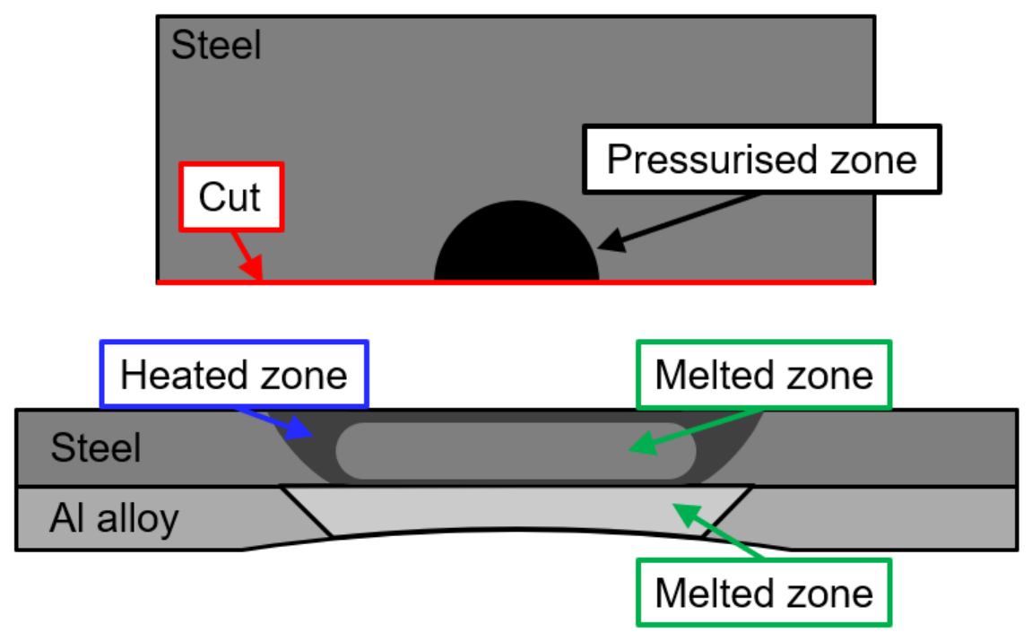
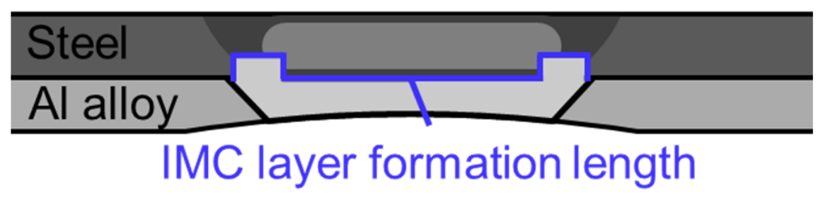
Cross-sectional observations and measurements of the IMC layer were conducted to evaluate the joint quality. The welded joints were sectioned at the center of the indentation and observed using an optical microscope, as shown in Figure 2. The IMC layer thickness distribution was determined by capturing images of the IMC layer region at 200 µm intervals from the left edge to the right edge. The IMC layer thickness was measured at five locations in each image, and the average value was calculated. Also, Figure 3 shows the measurement locations of the IMC layer formation length in a joint with a rectangular interface.

2.4. Tensile Shear Test Method

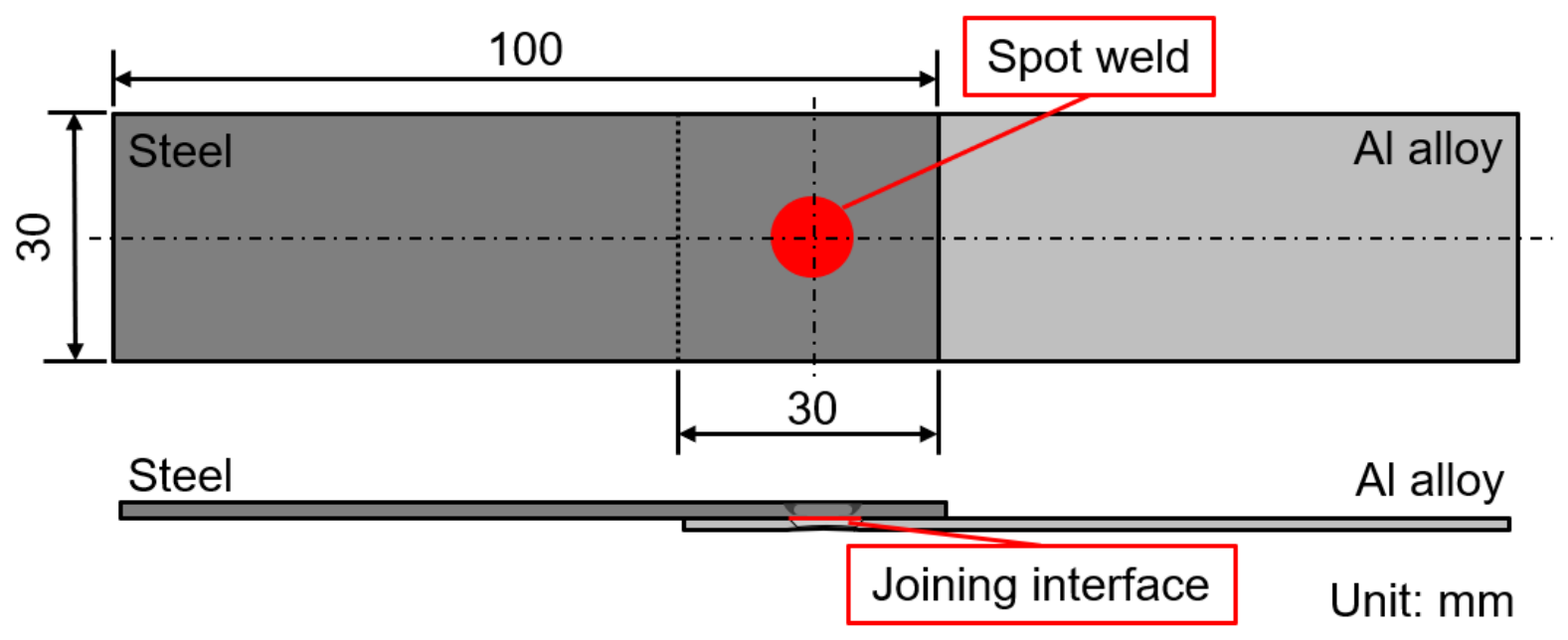
Tensile shear tests were conducted to evaluate the effect of interface geometry on joint strength. Tensile shear tests were conducted in accordance with JIS Z 3136 using test specimens measuring 30 × 100 mm, with three tests performed under each condition. (Figure 4) [9]. The crosshead speed was set to 1 mm/min.

3. Results and Discussion

3.1. The Feasibility of Improving TSS in Joints with Rectangular Interface

3.1.1. Interface Geometry and IMC Layer Formation Depending on the Presence or Absence of Grooves

Cross-sectional observations and measurements of IMC layer thickness distributions were conducted to determine whether a rectangular interface was formed in joints with and without grooving. The cross-sectional photographs are shown in Figure 5. As shown in Figure 5, a rectangular interface was formed in the grooved joint. These results confirm that grooving leads to the formation of a rectangular interface, consistent with previous reports showing improved peel strength.
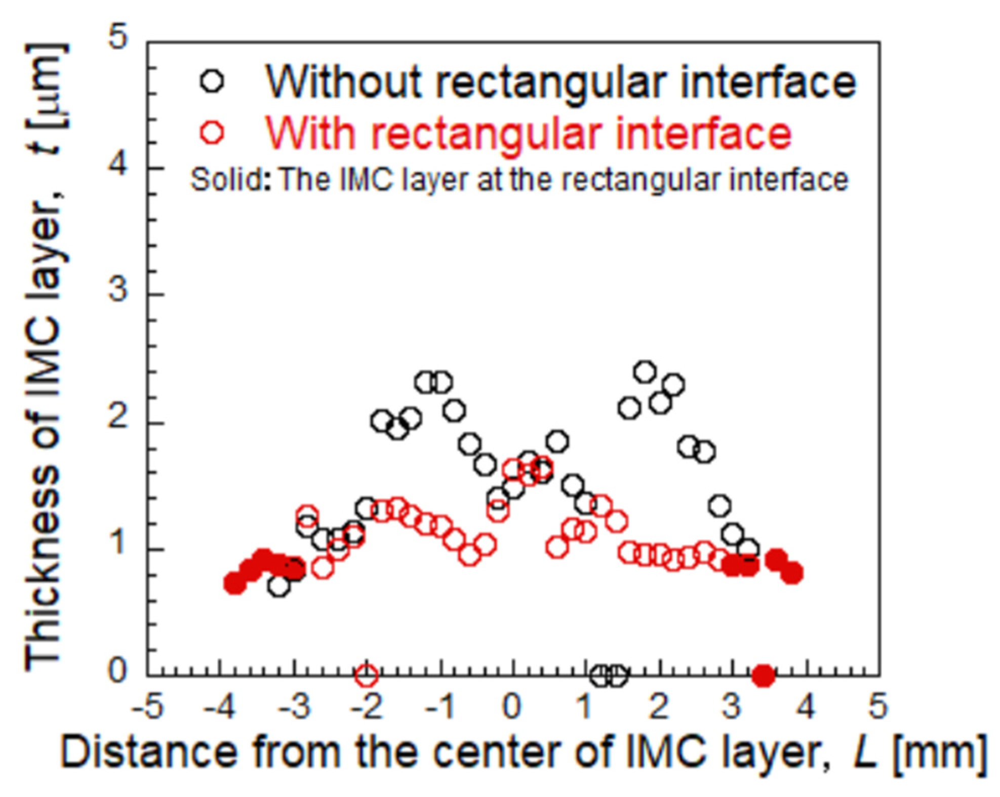
To evaluate the effect of a rectangular interface on IMC layer formation, the IMC layer thickness was measured. Figure 6 shows the measurement results. As shown in Figure 6, a relatively thin IMC layer was observed in joints with a rectangular interface. It is established that the growth behavior of IMC layers at steel–aluminum alloy interfaces is temperature dependent [10,11]. These results suggest that grooving alters the contact configuration between the materials, leading to reduced heat generation during welding.

3.1.2. The Effect of the Presence or Absence of a Rectangular Interface on TSS

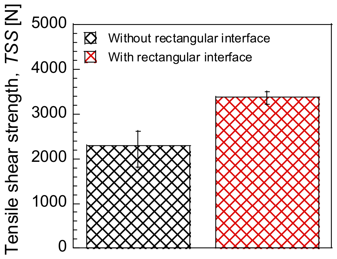
Tensile shear tests were conducted to evaluate the effect of a rectangular interface on TSS. Figure 7 shows the results of the tensile shear tests. As shown in Figure 7, TSS increased in joints with rectangular interfaces. To clarify the mechanism of this improvement, post-fracture cross-sectional observations were conducted. Photographs of the post-fracture cross-sections are shown in Figure 8. In joints without a rectangular interface (Figure 8a), fracture occurred at the interface. In contrast, in joints with a rectangular interface (Figure 8b), fracture occurred within the aluminum alloy base metal at the rectangular interface, as indicated by the red circle. These results suggest that the increase in TSS is attributable to the anchoring effect at the rectangular interface.
The results indicate that two main factors contribute to the increase in TSS. First, the formation of a relatively thin IMC layer contributes to improved TSS. Second, fracture analysis revealed that failure occurred within the aluminum alloy base metal at the rectangular interface, indicating the contribution of the anchoring effect. However, the relative contributions of these two factors have not been clearly distinguished. Further investigation is required to clarify the dominant mechanism governing the improvement in TSS.

3.2. The Relationship Between TSS and Anchoring Effect Due to Changes in Rectangular Interface Shape

The previous results indicate that both IMC layer formation behavior and the anchoring effect contribute to the increase in TSS. Therefore, in this section, the effect of rectangular interface geometry on TSS is investigated, with particular focus on the relationship between interface geometry, anchoring effect, and joint strength.

3.2.1. Effects of Groove Dimensions on Joint Interface Geometry and IMC Layer Formation

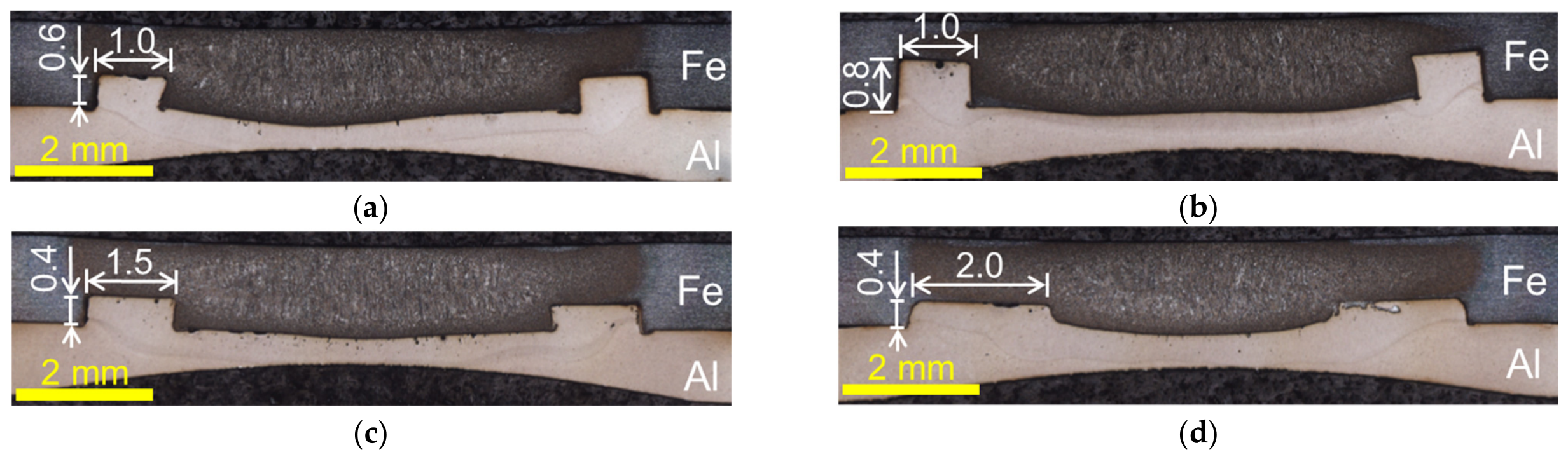
The groove depth and width were varied to examine their effects on the rectangular interface and joint morphology. Cross-sectional images for each groove condition are shown in Figure 9. As shown in Figure 9, the shape of the rectangular interface varied depending on the groove geometry. The aluminum alloy penetrated into the groove, forming a rectangular interface regardless of the groove shape.
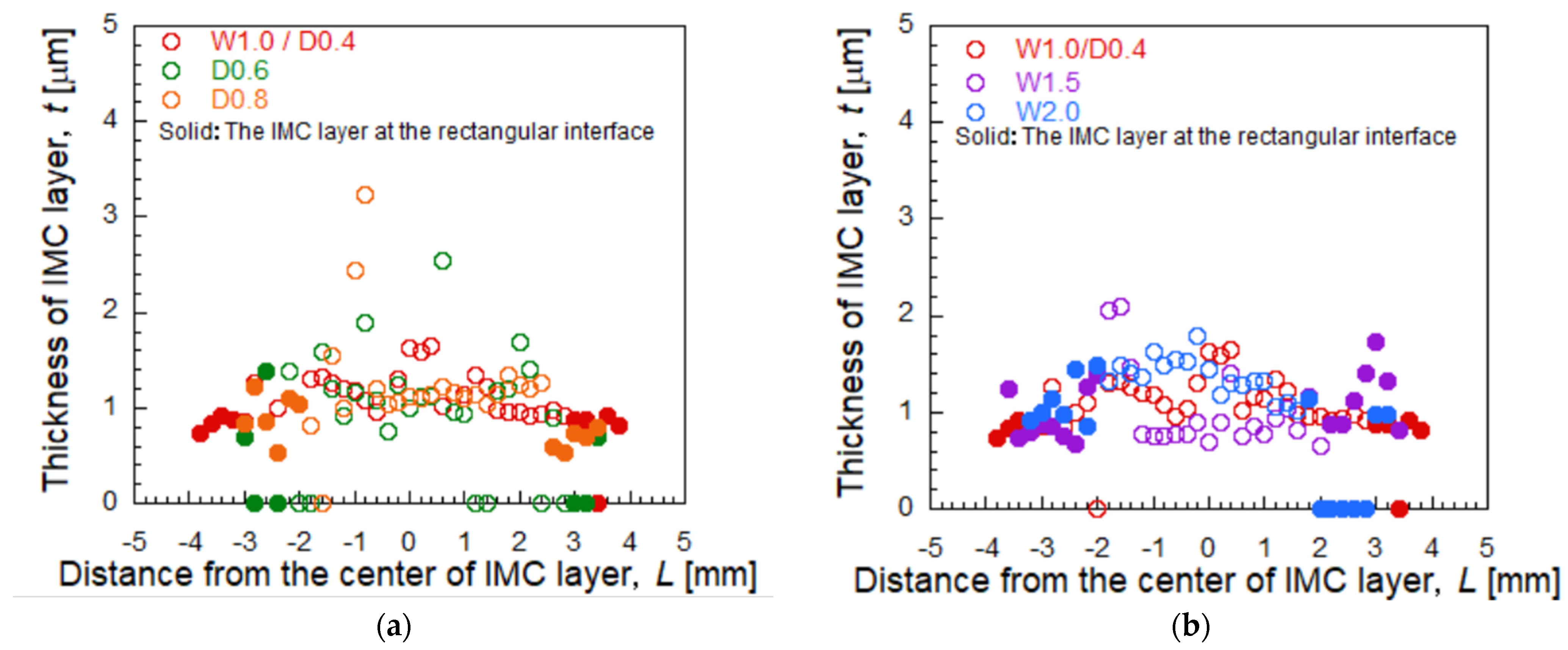
The IMC layer thickness distributions for each condition are shown in Figure 10. Under increased groove depth conditions (Figure 10a), the IMC layer was locally thicker in the central region compared to the W1.0/D0.4 condition; however, the overall IMC layer thickness remained similar. Similarly, under increased groove width conditions (Figure 10b), the IMC layer thickness was comparable to that of the W1.0/D0.4 condition. These results indicate that the IMC layer thickness is largely independent of the rectangular interface geometry.

3.2.2. The Effect of Rectangular Interface Shape on TSS

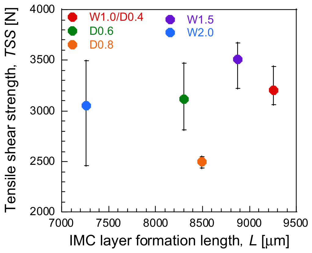
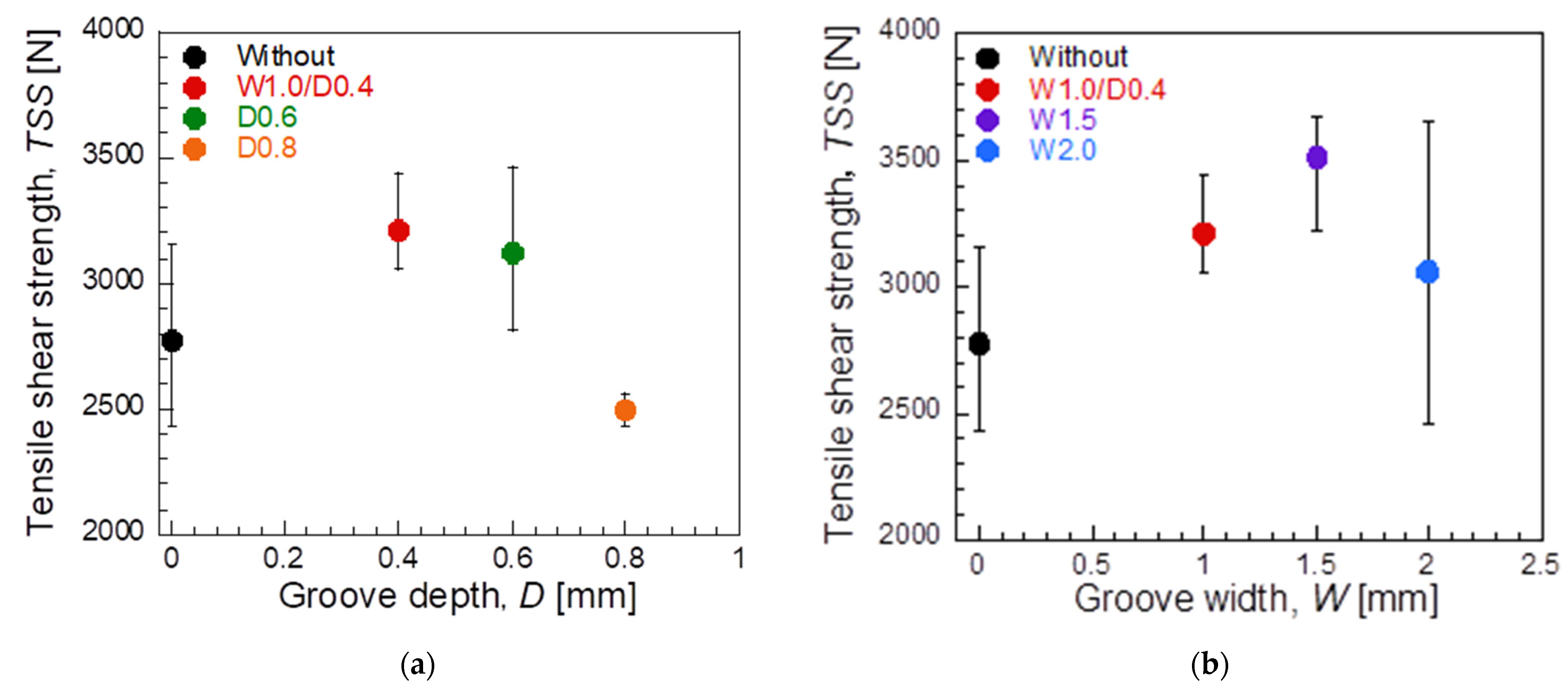
Tensile shear tests were conducted to investigate the relationship between the anchoring effect and TSS for different rectangular interface geometries. First, since it is necessary to examine the relationship between IMC layer formation length and TSS based on differences in rectangular interface shapes, Figure 11 summarizes the data by IMC layer formation length and TSS. The results show that under the W2.0, D0.6, and W1.5 conditions, TSS tends to increase as the IMC layer formation length increases. Under the W1.5 condition, TSS increased compared with the W1.0/D0.4 condition, even though the IMC layer formation length decreased. Furthermore, under the D0.8 condition, TSS decreased despite an increase in IMC layer formation length compared with the W2.0 and D0.6 conditions. This suggests that the shape of the rectangular interface may have influenced TSS more than the IMC layer formation length. Therefore, Figure 12 summarizes the differences in rectangular interface shapes and TSS. The results show that, as shown in Figure 12a, TSS decreased with increasing groove depth compared with the W1.0/D0.4 condition. In contrast, as shown in Figure 12b, under increased groove width conditions (Figure 12b), TSS increased at W1.5 but decreased at W2.0. A previous study has shown that reducing the thickness of aluminum alloys affects the reduction in TSS [12]. In this study, the reduction in the thickness of the aluminum alloy sheets may be attributed to differences in the rectangular interface geometry. However, under the W1.5 condition, although thinning of the aluminum alloy sheets is conceivable due to increased penetration into the grooved area compared to the W1.0/D0.4 condition, the TSS actually increased; therefore, it is considered that the effect of aluminum alloy thinning caused by differences in rectangular interface shapes on the TSS is minimal. In addition, in the previous section, since no significant differences in IMC layer thickness were observed under the various groove dimension conditions, the observed variation in TSS indicates that these results suggest that the anchoring effect associated with interface geometry strongly influences joint strength.
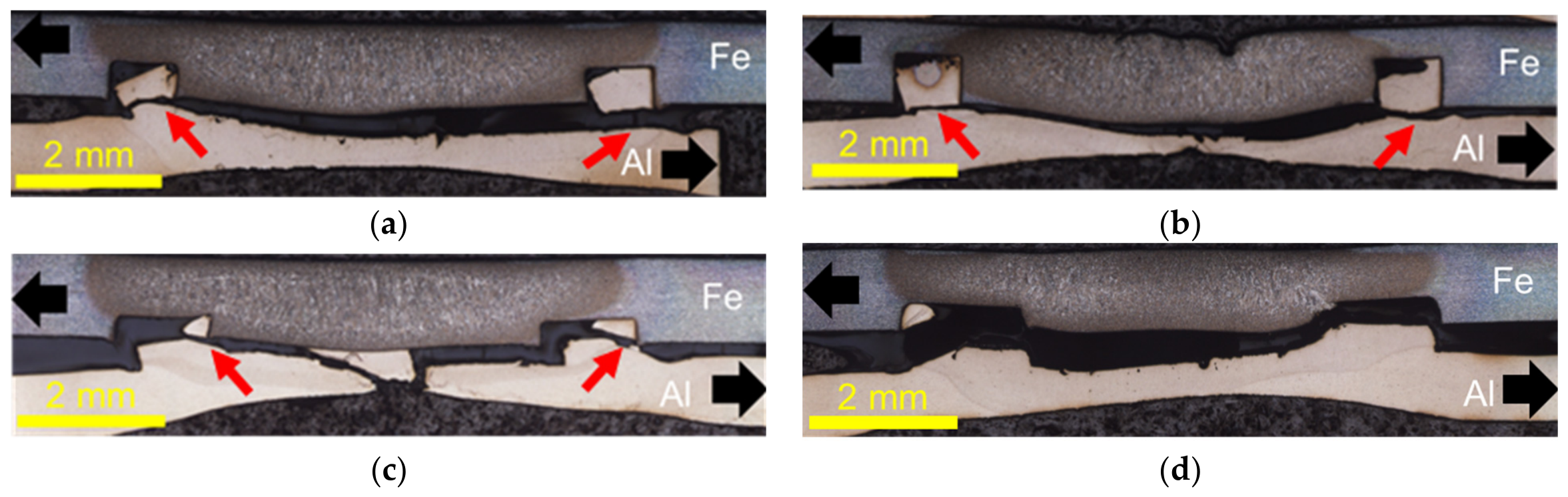
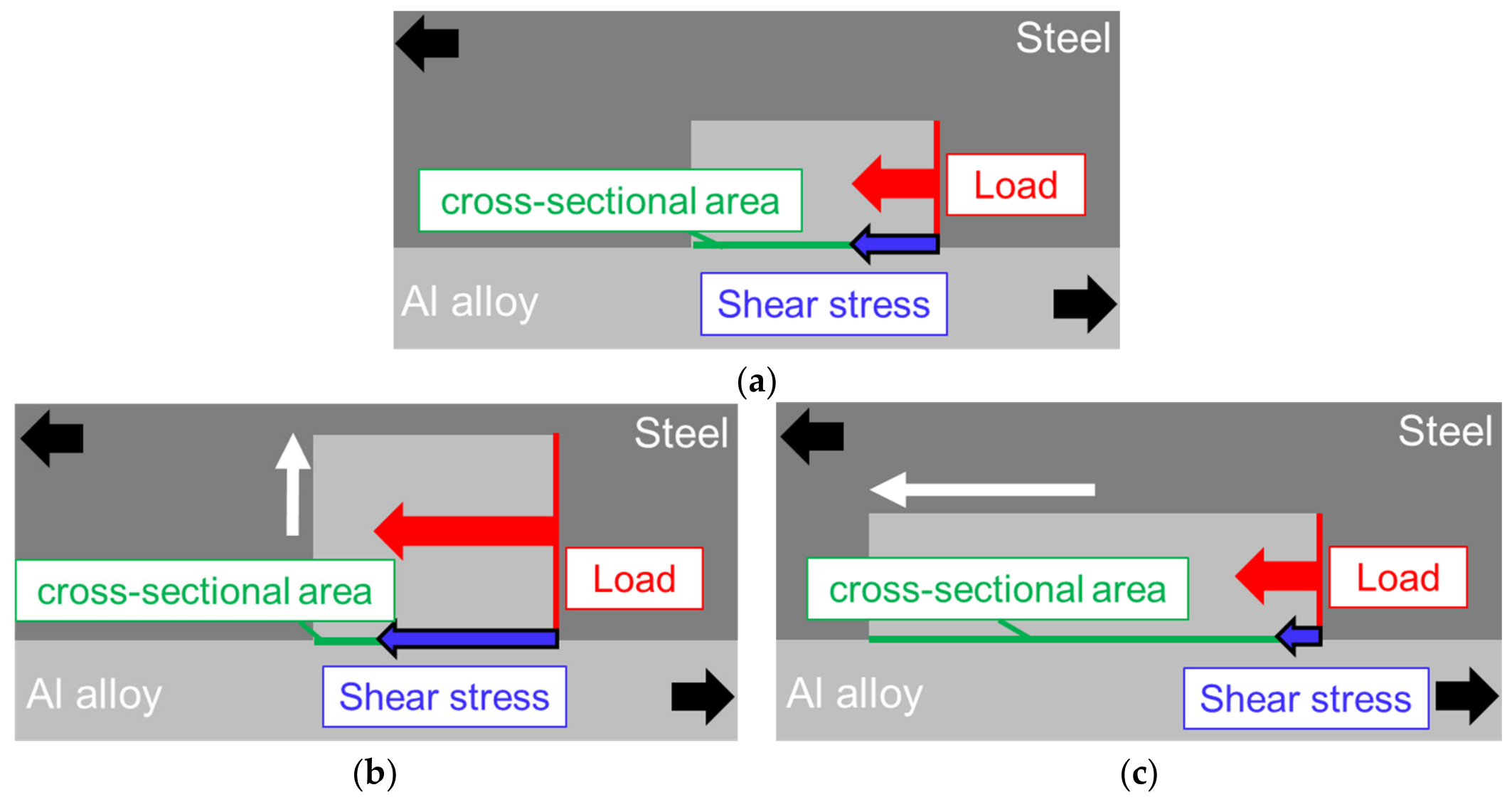
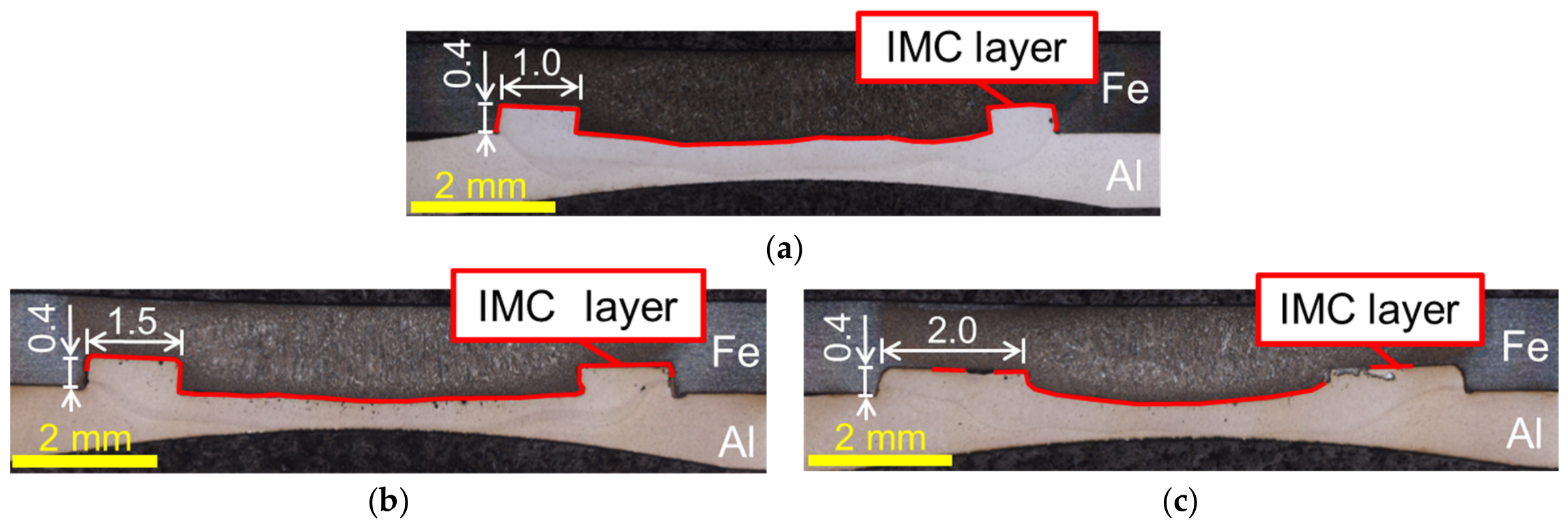
To investigate the relationship between the shape of the rectangular interface geometry and TSS, post-fracture cross-sectional observations were conducted. Photographs of the post-fracture cross-sections are shown in Figure 13. As shown in Figure 13, in the joints with increased groove depth (Figure 13a,b), damage to the aluminum alloy base metal occurred at the bottom of the rectangular interface, as indicated by the red arrows. In contrast, in the joints with increased groove width, crack propagation was observed in the aluminum alloy at the rectangular interface under the W1.5 condition, whereas failure occurred at the joint interface under the W2.0 condition. The mechanisms underlying these results are illustrated in Figure 14. As shown in Figure 14b, increasing the groove depth leads to a higher shear load at the rectangular interface, resulting in increased shear stress and a decrease in TSS. Conversely, as shown in Figure 14c, increasing the groove width increases the cross-sectional area of the rectangular interface, thereby reducing the shear stress and contributing to an increase in TSS. However, under the W2.0 condition, TSS decreased despite the increased groove width. It was considered that this was due to the fracture occurring at the joint interface. To clarify this behavior, the IMC layer formation was examined using cross-sectional observations. Figure 15 shows the distribution of the IMC layer under increased groove width conditions. As shown in Figure 15, under the W1.0/D0.4 and W1.5 conditions, the IMC layer formed up to the outer periphery of the rectangular interface. In contrast, under the W2.0 condition, the IMC layer was not observed at the outer periphery of the rectangular interface. These results indicate that although increasing the groove width reduces shear stress, the presence of an IMC layer at the interface periphery is essential for maintaining high TSS. Based on these results, TSS in joints with a rectangular interface is enhanced by both IMC layer formation at the interface periphery and the anchoring effect associated with the interface geometry.

4. Conclusions

This study investigated the feasibility of improving TSS in steel/aluminum alloy dissimilar material RSW joints using a rectangular interface. Joints with rectangular interfaces were fabricated, and cross-sectional observations and tensile shear tests were conducted. The following results were obtained.
  • The TSS increased in joints with rectangular interfaces due to the formation of a thin IMC layer and the anchoring effect.
  • The IMC layer thickness was generally similar among joints with different groove dimensions.
  • The TSS decreased in joints with increased groove depths of 0.60 mm and 0.80 mm.
  • The TSS increased at a groove width of 1.5 mm, whereas it decreased at 2.0 mm.
  • In joints with increased groove width, regions without IMC layer formation at the rectangular interface were observed under the W2.0 condition.

Author Contributions

Conceptualization, F.N. and M.I.; methodology, F.N. and M.I.; validation, F.N., K.K., T.I. and M.I.; investigation, F.N., K.K., T.I. and M.I.; data curation, F.N. and K.K.; writing–original draft preparation, F.N.; writing–review and editing, F.N.; supervision, M.I.; project administration, M.I.; funding acquisition, M.I. All authors have read and agreed to the published version of the manuscript.

Funding

This research was funded by Kobe Steel, Ltd. through a collaborative research agreement with Osaka Institute of Technology.

Institutional Review Board Statement

Not applicable.

Informed Consent Statement

Not applicable.

Data Availability Statement

No new data were created or analyzed in this study. Data sharing is not applicable to this article.

Conflicts of Interest

This research was conducted as part of a collaborative research project funded by Kobe Steel, Ltd. Tetsu Iwase is employees of Kobe Steel, Ltd. Kobe Steel, Ltd. was involved in the study design, interpretation of the results, and review of the manuscript. The other authors declare no conflicts of interest.

References

  1. Giampieri, A.; Ling-Chin, J.; Ma, Z.; Smallbone, A.; Roskilly, P. A review of the current automotive manufacturing practice from an energy perspective. Appl. Energy 2020, 261, 114074. [Google Scholar] [CrossRef] [Scilit]
  2. Shan, H.; Ma, Y.; Niu, S.; Yang, B.; Lou, M.; Li, Y.; Lin, Z. Friction stir riveting (FSR) of AA6061-T6 aluminum alloy and DP600 steel. J. Mater. Process. Technol. 2021, 295, 117156. [Google Scholar] [CrossRef] [Scilit]
  3. Li, M.; Tao, W.; Zhang, J.; Wang, Y.; Yang, S. Hybrid resistance-laser spot welding of aluminum to steel dissimilar materials: Microstructure and mechanical properties. Mater. Des. 2022, 221, 111022. [Google Scholar] [CrossRef] [Scilit]
  4. Walker, L.; Zhang, W. An investigation of the effect of steel alloying elements on iron-aluminum intermetallic characteristics for dissimilar resistance spot welding. Mater. Des. 2024, 248, 113514. [Google Scholar] [CrossRef] [Scilit]
  5. Jabar, S.; Baghbani, A.; Franciosa, P.; Kotadia, H.R.; Ceglarek, D. Effects of the adjustable ring-mode laser on intermetallic formation and mechanical properties of steel to aluminium laser welded lap joints. Mater. Des. 2023, 227, 111774. [Google Scholar] [CrossRef] [Scilit]
  6. Zhang, W.; Sun, D.; Han, L.; Gao, W.; Qiu, X. Characterization of intermetallic compounds in dissimilar material resistance spot welded joint of high strength steel and aluminum alloy. ISIJ Int. 2011, 51, 1870–1877. [Google Scholar] [CrossRef] [Scilit]
  7. Iwase, T.; Sasabe, S.; Matsumoto, T.; Tanigawa, M.; Tawara, M.; Hattori, Y. Dissimilar metal joining between aluminum alloy and hot-dip aluminized steel sheet, new materials and technologies for automobile bodies. Kobelco Technol. Rev. 2008, 28, 29–34. [Google Scholar]
  8. Kubo, K.; Tomari, K.; Iwase, T.; Iyota, M. Relationship between convex surface shape and joint strength of steel/aluminum alloy dissimilar materials resistance spot welded joint. In Proceedings of the 147th Conference of Japan Institute of Light Metals, Ota City, Japan, 8–10 November 2024; pp. 515–516. [Google Scholar]
  9. JIS Z 3136; Specimen Dimensions and Procedure for Tensile Shear Testing of Spot and Projection Welded Joints. Japanese Standards Association: Tokyo, Japan, 2025.
  10. Kutsuna, M.; Rathod, M. Laser roll bonding of A5052 aluminium alloy and SPCC steel. Q. J. Weld. Soc. J. 2003, 21, 282–294. [Google Scholar] [CrossRef] [Scilit]
  11. Yamashita, S.; Saida, K. Evaluation of growth rate of intermetallic compound during dissimilar laser brazing of steel and aluminum alloy using Al-Si filler metal. Q. J. Weld. Soc. 2023, 41, 242–247. [Google Scholar] [CrossRef] [Scilit]
  12. Miyamoto, K.; Nakagawa, S.; Sugi, C.; Tsushima, K.; Iwatani, S.; Hojo, S.; Ogura, T.; Hirose, A.; Kobayashi, F.K. Dissimilar metals joining of steel and aluminum alloy by resistance spot welding-Dissimilar metals joining of steel and aluminum alloy by Zn insertion. Q. J. Jpn. Weld. Soc. 2014, 32, 83–94. [Google Scholar] [CrossRef] [Scilit]
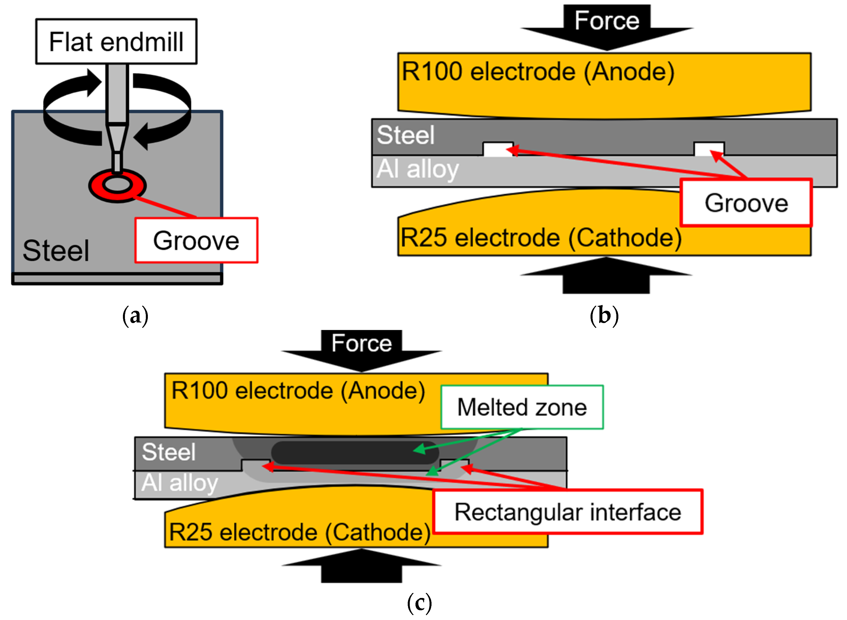
Figure 1. Schematic diagram of the method for fabricating rectangular interface: (a) Grooving method; (b) Before current application; (c) After current application.
Engproc 151 00017 g001
Figure 2. Methods for cross-sectional observation.
Engproc 151 00017 g002
Figure 3. Schematic diagram at the measurement location of the IMC layer formation length.
Engproc 151 00017 g003
Figure 4. Dimension of tensile shear test specimen.
Engproc 151 00017 g004
Figure 5. Cross-sectional macro photographs showing the presence or absence of rectangular interface: (a) Without rectangular interface; (b) With rectangular interface (W1.0/D0.4).
Engproc 151 00017 g005
Figure 6. The effect of rectangular interface on IMC layer thickness in the IMC layer formation zone.
Engproc 151 00017 g006
Figure 7. The effect of rectangular interface on TSS.
Engproc 151 00017 g007
Figure 8. The effect of rectangular interface on fracture morphology; (a) Without rectangular interface; (b) With rectangular interface (W1.0/0.4). (The red circle indicates the location where fracture occurred within the aluminum alloy base metal at the rectangular interface).
Engproc 151 00017 g008
Figure 9. Formation morphology of rectangular interface due to changes in groove dimensions: (a) D0.6; (b) D0.8; (c) W1.5; (d) W2.0.
Engproc 151 00017 g009
Figure 10. Thickness of IMC layer distribution during changes in rectangular interface shape: (a) Increased groove depth dimension; (b) Increased groove width dimension.
Engproc 151 00017 g010
Figure 11. The relationship between IMC layer formation length and TSS.
Engproc 151 00017 g011
Figure 12. The relationship between rectangular interface shapes and TSS: (a) Increased groove depth dimension; (b) Increased groove width dimension.
Engproc 151 00017 g012
Figure 13. The effects of rectangular interface shape on fracture morphology: (a) D0.6; (b) D0.8; (c) W1.5; (d) W2.0. (The red arrows indicate the location where fracture occurred within the aluminum alloy base metal at the rectangular interface).
Engproc 151 00017 g013
Figure 14. Schematic diagram illustrating the effect of rectangular interface geometry on shear stress: (a) W1.0/D0.4; (b) Increasing groove depth dimension; (c) Increasing groove width dimension.
Engproc 151 00017 g014
Figure 15. Formation zones of IMC layer in rectangular interface shapes due to increased groove width: (a) W1.0/D0.4; (b) W1.5; (c) W2.0.
Engproc 151 00017 g015
Table 1. Chemical composition of 980 MPa-class steel (wt%).
CSiMnPSFe
0.0840.4812.530.0120.003Bal.
Table 2. Chemical composition of A6061-T6 alloy (wt%).
SiFeCuMnMgCrZnTiAl
0.610.420.281.00.240.240.050.04Bal.
Table 3. Welding conditions for rectangular interface joints.
Electrode Force, F (kN)Current, I (kA)Current Time, tW (Cycles)Hold Time, th (Cycles)
3.7161299
Table 4. Conditions for groove dimension with changed width and depth increased.
Condition NameOuter Diameter, Do (mm)Groove Width, W (mm)Groove Depth, D (mm)
W1.0/D0.48.01.00.4
D0.60.6
D0.80.8
W1.51.50.4
W2.02.0
Disclaimer/Publisher’s Note: The statements, opinions and data contained in all publications are solely those of the individual author(s) and contributor(s) and not of MDPI and/or the editor(s). MDPI and/or the editor(s) disclaim responsibility for any injury to people or property resulting from any ideas, methods, instructions or products referred to in the content.