1. Introduction
Low-cost automation is a global trend for automating discrete manufacturing processes. The need to increase the competitiveness of enterprises to enter international markets makes low-cost automation particularly relevant.
Low-cost automation systems (LCASs) are widely used in various fields, mechanical engineering, electronics and electrical engineering, metallurgy and metal casting, the food industry, etc., in the automation of various technological operations—pressing, drilling, threading, assembly, etc. [
1,
2,
3,
4,
5,
6,
7]. These systems are particularly effective in production runs with medium to high production volumes, i.e., die cast parts and injection-molded parts (for example connectors used in electronic devices).
The application of LCASs in the automation of control and sorting operations is particularly promising, since the continuous increase in the requirements for the quality of products leads to an increase in the role of these operations, which are characterized by labor intensity, monotony, etc. Characteristic features of automatic sorting systems include high cost, complex design, need for personnel for maintenance and repair with special knowledge, etc. Increasing the efficiency of control and sorting operations is achieved in two main ways—by choosing an optimal control plan and by reducing investment costs for technical means. The first method is applied in sample percentage control by minimizing the volumes of samples while maintaining reliability [
8]. With 100% control and sorting, only the second method remains.
The purpose of this paper is to present some approaches and methods implemented by the authors to develop a system for sorting plastic products (connectors) with complex shapes at maximum productivity and minimal costs.
2. Assessing the Suitability of Parts for Automatic Sorting
When developing a project to automate the production of any product, it is necessary to analyze its design and technological process. The analysis allows us to assess the degree of suitability of the design of the product for automated production and the feasibility of the development even in the early stages of design [
9]. The feasibility of the product for automatic feeding, orienting and sorting is a relative concept and depends on the adopted sorting method and the technical means provided for this purpose.
To analyze the degree of suitability of parts for automatic sorting, a methodology for quantitative assessment of the manufacturability of products is used, discussed in [
10]. The methodology is based on an element-by-element analysis of the product design from the point of view of the possibility and technical feasibility of automatically performing the following manipulation functions: orienting the parts in space and time; feeding into the work area; establishing the parts in working positions; transportation; and unloading. The methodology evaluates the basic properties of the parts: configuration, adhesion, shape, material, dimensions and their relationships, symmetry, specific properties, etc. The properties of the parts are grouped into seven levels, with each level characterizing a qualitatively defined set of properties. To quantitatively assess the degree of suitability of the parts for automatic production, a numerical code designation is assigned to each level, determined by experts. The numerical value of the code takes into account the complexity of automation and determines the complexity score for the level under consideration. The complexity score meaning is given in
Table 1.
Based on the sum of the digits of the code number for all grades, the suitability of the part for automatic production is judged. If the evaluation of a given product shows that it is in the third or fourth category of complexity, then automatic production is very complicated and even impractical.
Table 2 shows the results of the expert assessment of the parts of the type “Connector”.
The complexity score of the parts is b = 20, therefore it is in the second category of complexity. Hence, the automation of the sorting of parts is of medium complexity. From this, we see that a VBF is feasible to be used as a feeding and orienting device. It is necessary to work out the system used for orienting when feeding parts. It is advisable to carry out experimental verification of the adopted design solutions.
3. Choosing the Optimal Variant of the Automatic Control and Sorting System
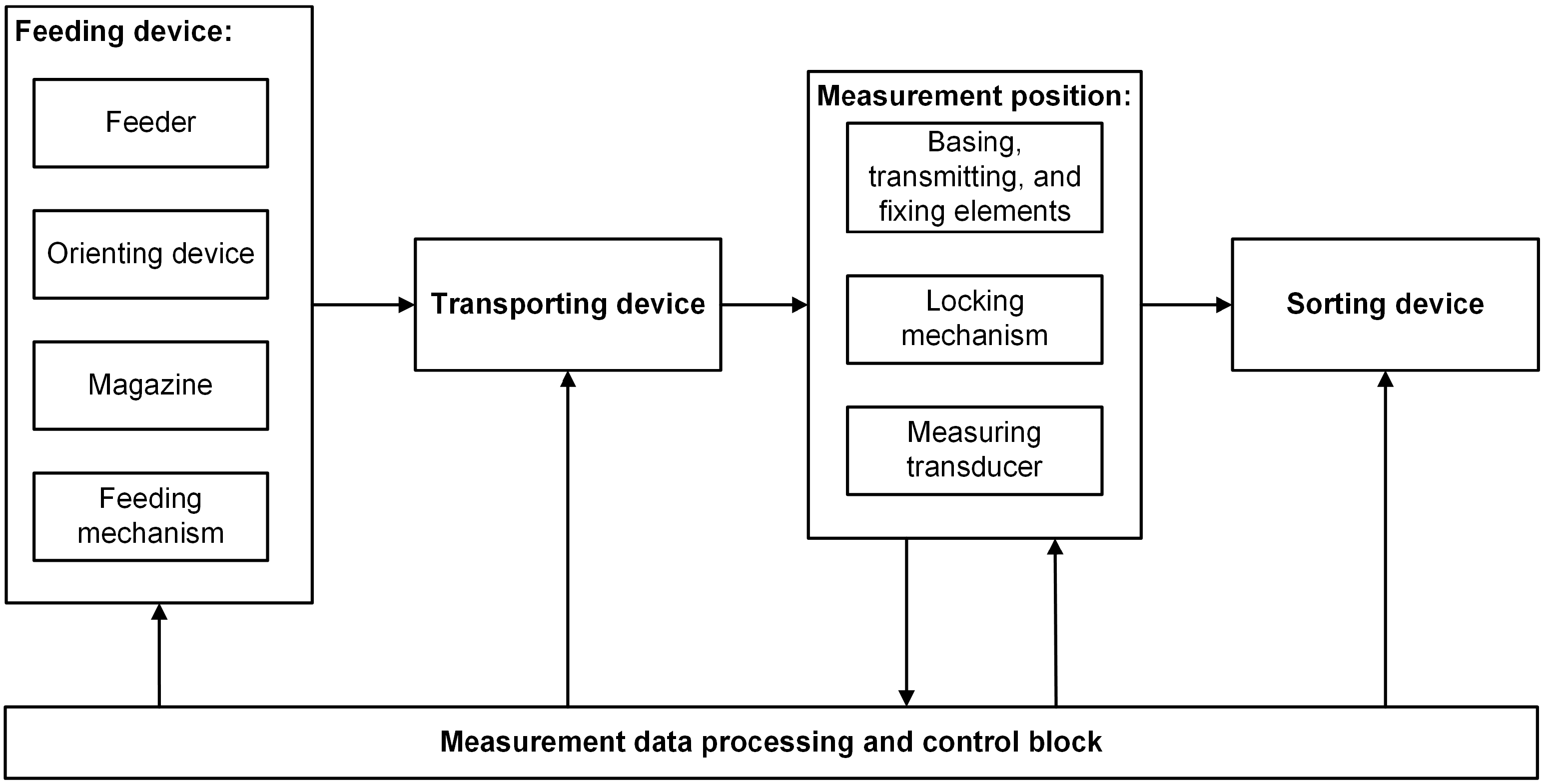
The classic version of a control and sorting machine (CSM) is shown in
Figure 1. The main characteristic of the machine—production rate Q—depends primarily on the control time, the number of measuring positions and the overlap of the times for feeding, orienting, transportation and sorting.
Based on the specifics of the parts and the requirement for maximum production rate, control is best implemented non-contact, in continuous motion, which results in three methods.
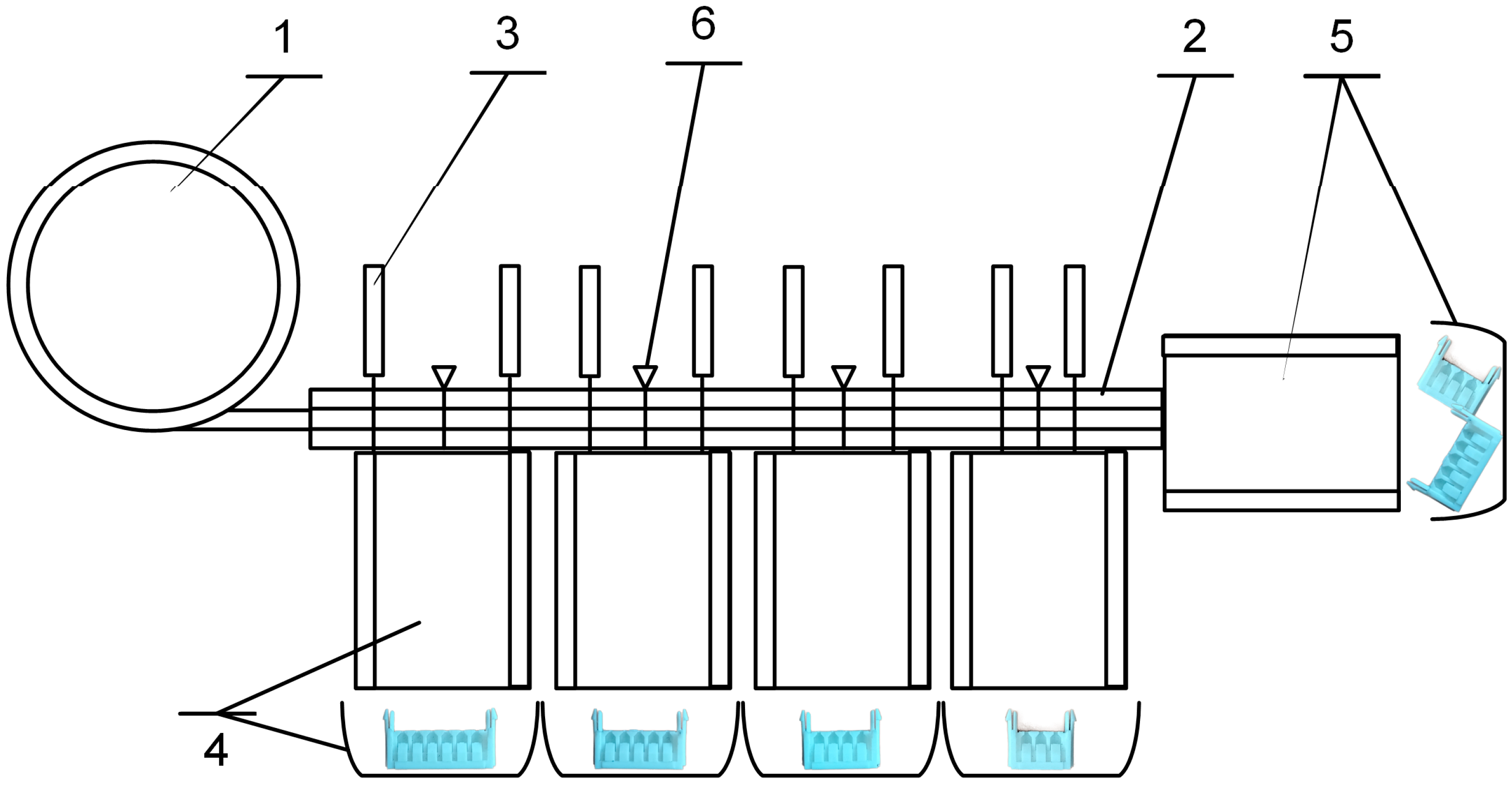
The first method is as follows: control with photoelectric converters with transmitted light [
11] (
Figure 2). The number of necessary optical “emitter–receiver” pairs is 8—two for each size. In order to implement the sorting, it is necessary to have a time interval between the parts, depending on the speed of the sorting devices (e.g., with an electromagnetic drive) and the distance to the most distant one. The sorting devices are controlled directly by signals from the optical pairs.
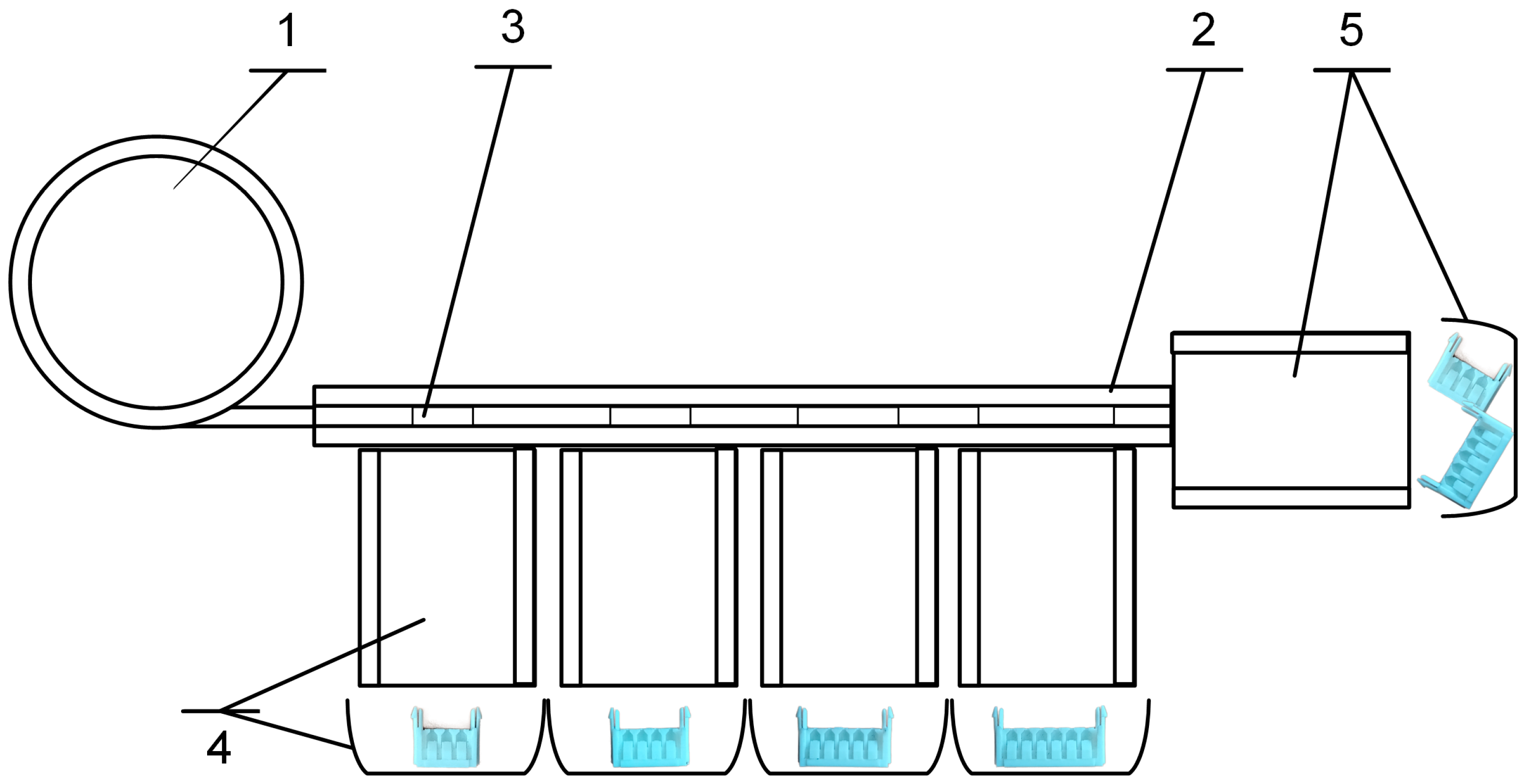
The second method is through passing gauges (
Figure 3). The step between the standard sizes in length (2.5 mm) is sufficient for its implementation. The shifted center of gravity at the most probable position of the part (N1,
Table 3) allows the use of incomplete profile gauges, arranged sequentially in increasing control size. This eliminates the need for measuring, comparing and sorting. In this method, these functions are combined. The simplified design and high reliability, and the relatively low price, make this option preferable.
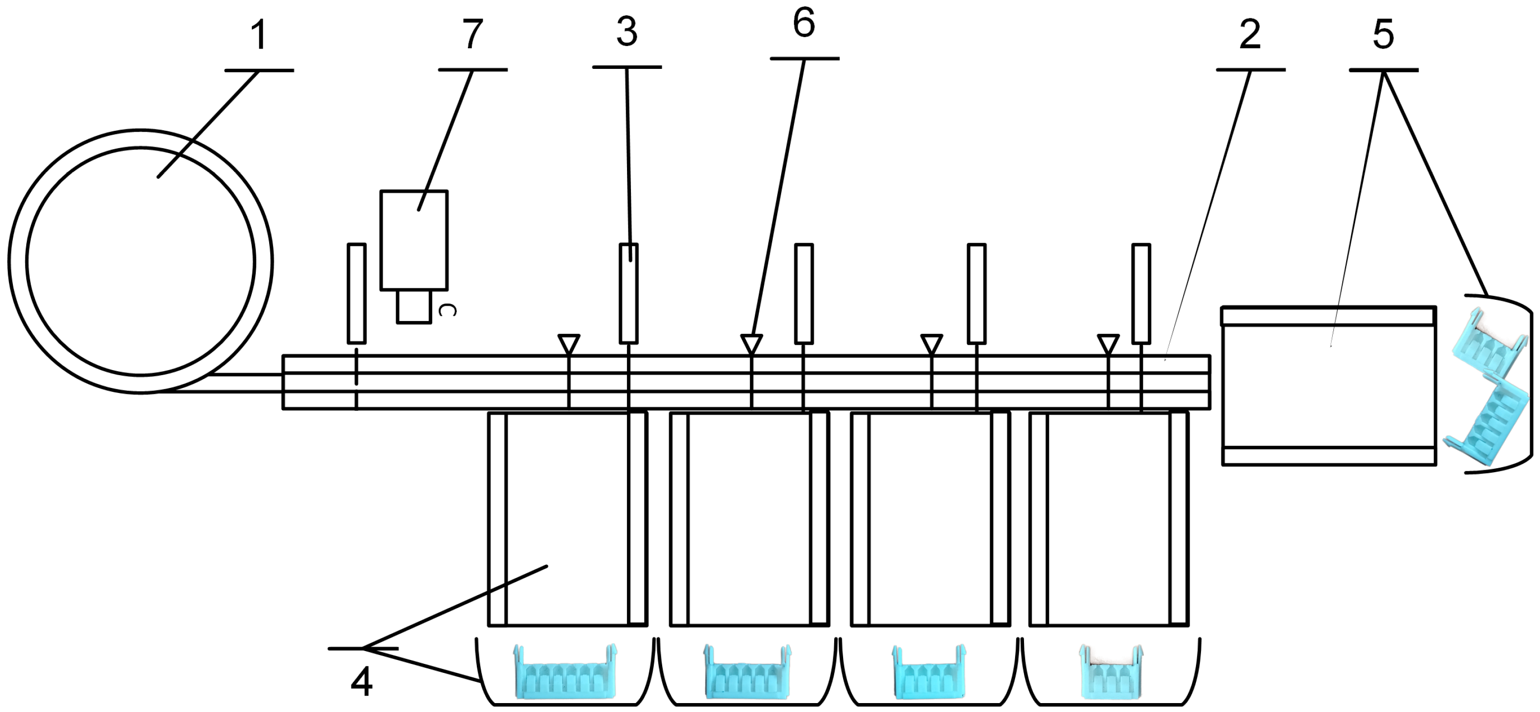
The third method uses a machine vision camera [
12,
13,
14] (
Figure 4). A possible application of the method is by means of photoelectric transducers with transmitted light and a set of compressed air nozzles equal to the number of sorted parts. The transducer and the nozzles are installed one after the other (sequentially) along the length of the transport path. In this scheme, it is necessary for the parts to pass in front of the sensor individually and they must be oriented so that they lie on their wider part (the lower row for positions 1–4 and the upper row for position 5 in
Table 2). Automated transport can be implemented both by means of a conveyor belt and by means of a vibratory feed track. The photoelectric transducers are installed as follows: the first one just before the camera and the next four just before the nozzles, relative to the direction of movement of the parts. The first serves as a capture trigger, giving a signal to the camera to capture when a part passes in front of the lens, and the rest are triggers for the nozzles. The camera recognizes the corresponding type of part and controls the nozzles, each of which can blow the part to a magazine for the corresponding type. The advantages of this solution are the greater flexibility in terms of the different stable positions that the camera can recognize—and then sort through the nozzles—and the fine tuning that the control system allows, independent of the manufacture of physical components such as calibers, but dependent on the software settings. The disadvantage is the significant cost of the system, mainly coming from the machine vision camera—the more complex control system compared to the other two variants and with its maintenance requiring qualified personnel.
After developing conceptual models of sorting systems using the three methods described, and based on information on the prices of the components [
15,
16,
17] and an expert assessment of the costs of design and manufacture, the estimated prices of the sorting systems were determined, shown in
Table 4.
As can be seen from
Table 4, the system using passing gauges for sorting the parts has the lowest cost and it was selected for design.
The selected method of control and sorting has a theoretical productivity
, which is limited by the time for the parts to fall through the gauges. The clearance between the part and the gauge
is from 0.7 mm to 1 mm. The speed of movement is limited by the condition for the part to fall through the gauge:
where
is the movement speed of the part, m/min;
—the clearance between the part and the gauge, mm;
—the thickness of the part, mm; and
—the acceleration due to gravity, m/s
2. For the specific case at
= 4 mm the speed
is 2 m/min. At an average length of the parts
= 16 mm, the value of
is 125 parts/min.
After analyzing the type of sorted parts and the requirements for maximum productivity and reliability, and based on practical experience and recommendations in specialized sources in the literature, a vibratory bowl feeder (VBF) is selected. The performance of the VBF
depends on the speed of the parts v, the length
and the grip coefficient
The grip coefficient can be determined most accurately experimentally; it is usually 0.6–0.9. The resulting performance is reduced depending on the number of orienting devices used and the average amount of parts removed from the flow. Thus, the design performance of the VBF
is obtained
where
is the probability of occurrence of the unwanted aspect of the part, and
—the number of unwanted natural resting aspects. This probability depends on the position of the center of gravity and the degree of stability of the corresponding aspect. The determination can be done by expert assessment or experimentally.
Table 2 gives the possible natural resting aspects of the sorted parts and the values of P
i for them, determined experimentally.
Taking into account the specified reduction factors, the performance of the VBF results in a working range of 45 parts/min to 70 parts/min.
The system operates as follows: The parts are poured in the bowl of the feeder and assume random orientations. Their primary and secondary orientation in space is performed by the VBF. A passive contact system for automatic orienting has been developed, including the following types of orienting devices—“narrowing of the chute” and “barrier”. In the first device, all parts that are in natural resting aspects NN 2, 3 and 4 (see
Table 2) are removed, and by means of the second orienting device, the parts are brought into a single-layer flow and parts in position N5 are removed (see
Table 2). The incoming chute of the VBF parts in position N1 (see
Table 2) enter the control and sorting system located on the balanced vibratory feeder. The parts, sorted by size, fall into the corresponding magazines under the action of gravity. Incorrectly sorted parts are separated into an auxiliary magazine.
The developed automatic orientating system is characterized by a reduction in the number of main functional devices compared to the classical functional structure of control and sorting machines (
Figure 1). In the proposed variant, they are reduced to two devices: a feeding device, performing the functions of automatic feeding and orienting of parts in space; and a multifunctional device, performing the functions of transportation, control and sorting. This leads to a simplification of the design, increased reliability, ease of maintenance, reduction in investment costs and an increase in the efficiency of control and sorting operations.
4. Low-Cost Automation System for Sorting Parts of Type “Connector”
The system is designed for automatic sorting of four sizes of “Connector”-type parts (
Figure 5). The parts have a complex shape and are produced by injection molding. The proposed system is also suitable for parts of a similar shape that are produced by die casting processes.
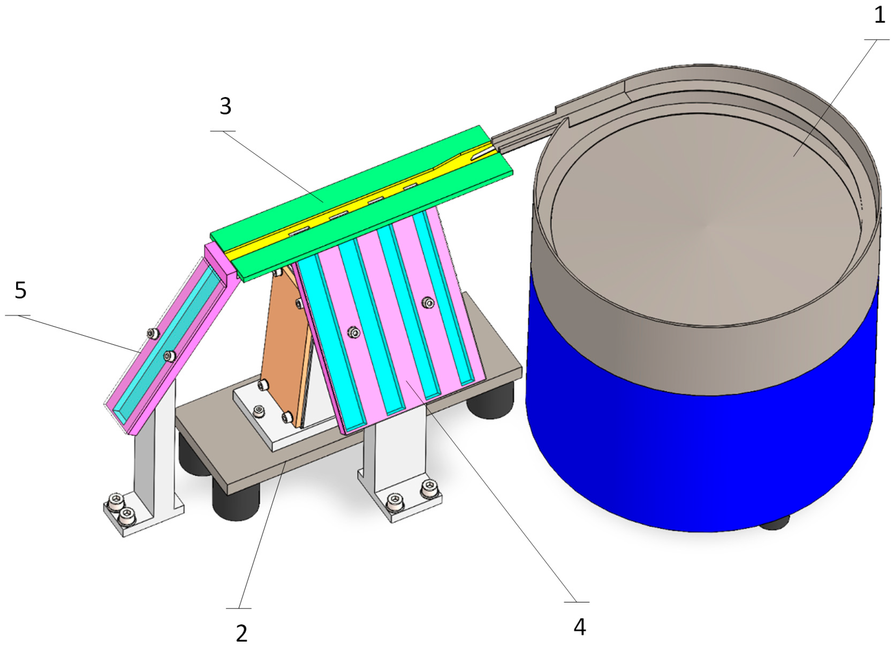
Figure 6 shows the general view of the designed system parametric CAD model. It consists of a vibrating bowl feeder (1), a balanced vibratory feeder (2), a sorting device with gauges (3), magazine for sorted parts (4 pcs.) (4), an auxiliary magazine for incorrectly sorted parts (5), and a device for regulating the speed of movement of the parts (not shown in the figure).
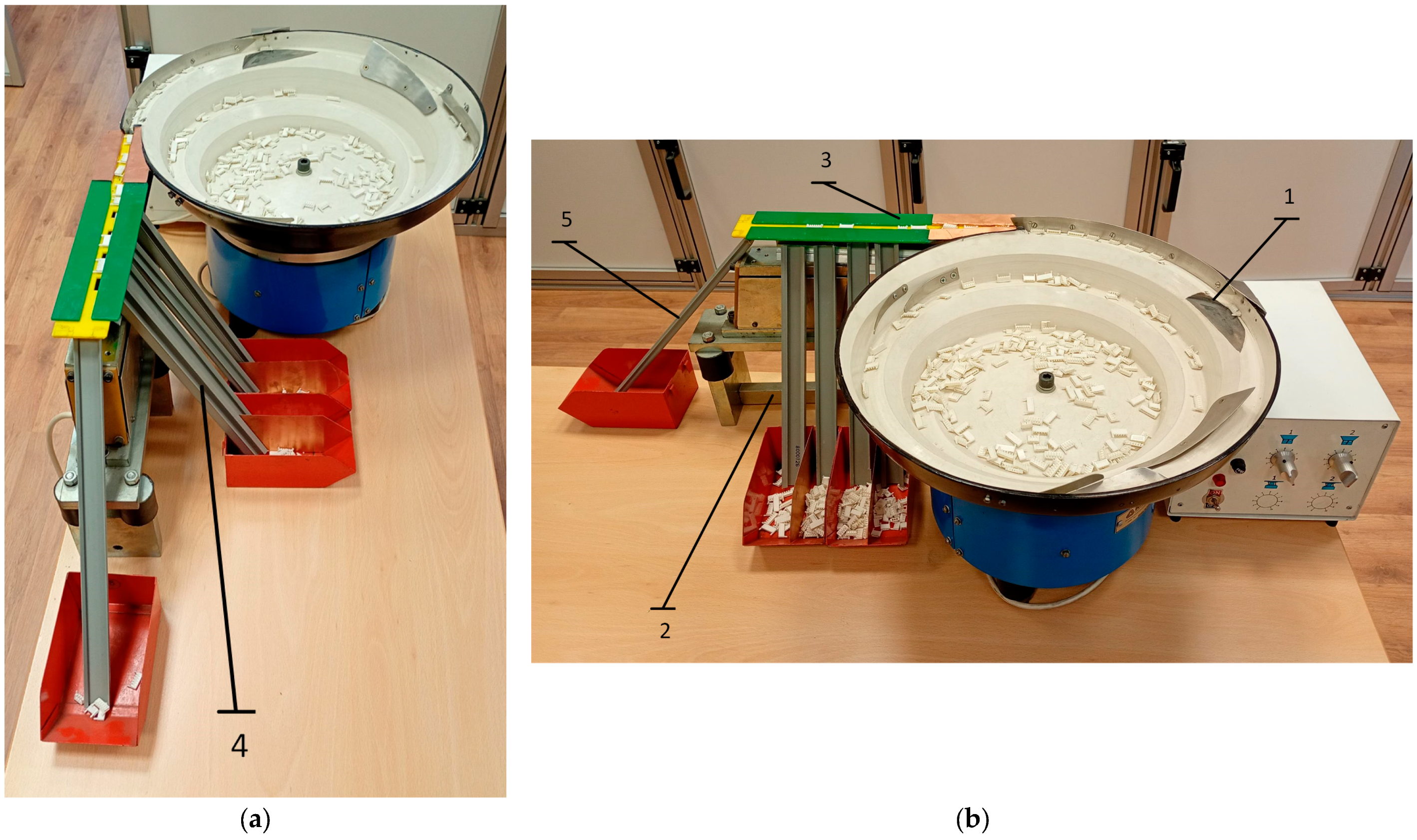
In
Figure 7, a prototype of the presented in
Figure 6 designed system is shown. The results of the sorting of 1000 parts are presented by a classification matrix (
Table 5). The main diagonal contains the correctly sorted parts, while the off-diagonal elements reflect single cases of misclassification. The resulting matrix structure shows high efficiency of the system, with errors having a one-way nature and being limited to neighboring groups of larger sizes. This behavior is consistent with the sequential principle of sorting by gauges and confirms the absence of inverse classification. The overall accuracy, defined as the ratio between the number of correctly sorted and the total number of analyzed parts, reaches 99.4%, which indicates that the influence of boundary effects in the sorting is limited and does not lead to a significant deterioration of the results.
The analysis of the accuracy by groups shows a high degree of uniformity of the results, which is an indication of well-chosen classification boundary values and the absence of systematic shift in the sorting process. This analysis is illustrated in
Table 6 based on the experiments performed.
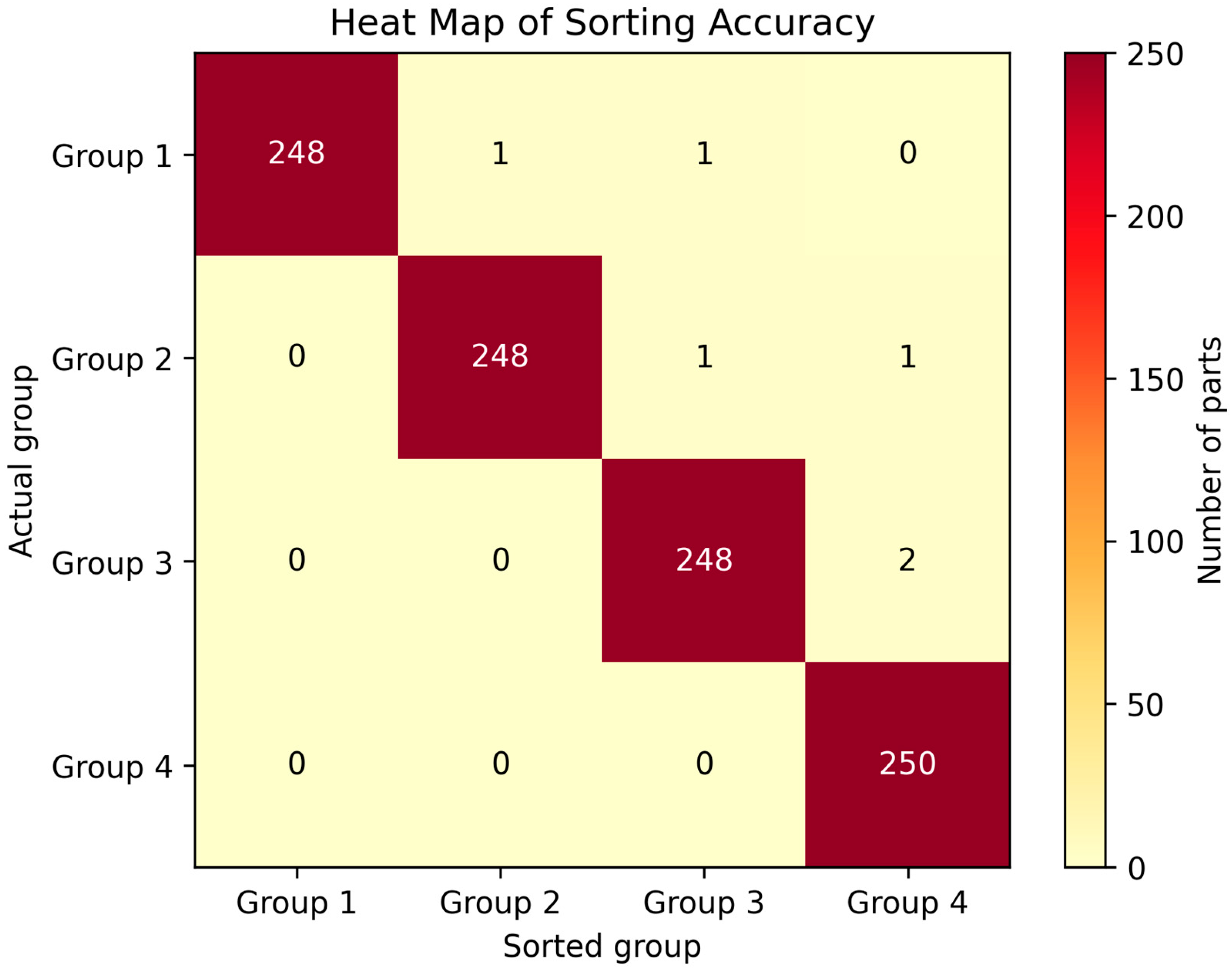
The heat map presented in
Figure 8 visualizes the results of the automatic sorting of parts using a color scale reflecting the number of elements in each combination of a reference and a specific group. The clearly expressed main diagonal indicates high accuracy of the system. A one-way nature of the errors is observed, with deviations occurring only in neighboring groups with larger sizes, which is consistent with the physical logic of the sorting process. The last group does not contain misclassified parts, which confirms the full reliability of the sorting for the largest sizes.
The resulting matrix structure has a triangular nature, which indicates that the errors are not random, but are determined by the sequential sorting principle and the calibration boundary conditions.
The technical data of the LCAS for sorting of “Connector”-type parts are shown in
Table 7.
To assess the economic efficiency of the developed system, the production cost and the payback period of the capital investments are determined. For comparison, an existing variant of manual sorting of the parts by three workers with an actual productivity of 3600 pcs./h and a single-shift operation mode is used.
The production cost of sorting is determined by the formula [
18]:
where
is the production cost, EUR/pc.;
—the costs of service personnel, EUR/h;
—the costs of production equipment (value of one machine hour), EUR/h; and
—the actual hourly rate of production of the workstation, pcs./h.
The value of one machine hour is determined by the formula [
19]:
where
,
,
,
,
are the annual costs, respectively for depreciation, interest, maintenance and repair, premises and energy, EUR/year; s—number of work shifts; and
—the actual annual working hours for a single-shift operation, h,
.
The costs included in Formula (5) are determined as follows [
19]:
where
are the up-to-date costs for building the sorting system, EUR;
—the price (capital investment) of the sorting system, EUR;
—the discount rate of capital investment (annual percentage depreciation of the national currency, average interest rate for long-term loans); and
—the economic period of use of the system (depreciation period), years.
where
is the calculated annual interest rate. Its value is equal to the interest rate for long-term loans [
19].
where
,
are the overall dimensions of the sorting system, m;
—the coefficient taking into account the additional area,
; and
—the annual costs per unit of occupied production area, €/m
2.
where
represents the annual electricity costs, kWh;
—the annual compressed air consumption, m
3;
—the price of electricity, EUR/kWh; and
—the price of compressed air, EUR/m
3.
Table 8 shows the values of the main economic parameters of the manual and automated sorting systems.
Table 9 shows the results obtained for the production cost.
The payback period
in years for capital investments is determined by the dependence:
where indices 1 and 2 refer to the values of the technical and economic characteristics, respectively before and after the implementation of the automated sorting system.
After substituting the data from
Table 9 in (11), the following is obtained:
Therefore, the payback period of the designed system is 2 months, i.e., the designed system meets the condition for low-cost automation systems, whose payback period must be less than 1 ÷ 2 years.