


Abstract
In recent years, the use of aluminum alloys in the automotive industry has been increasingly promoted to achieve lightweight vehicle bodies. Meanwhile, resistance spot welding (RSW) has long been widely employed for automotive body assembly, and thus considerable efforts have been devoted to improving the weldability of aluminum alloys by RSW. In particular, the stability of nugget formation, i.e., the molten region, during consecutive welding has emerged as a critical technical challenge. In this study, electrode wear, which is a key factor influencing nugget formation, was investigated to improve the continuous spot weldability of aluminum alloys. The relationship between the extent and morphology of electrode wear and nugget formation behavior was systematically examined. Furthermore, the electrode wear morphology that enhances continuous weldability was identified. The results revealed that stable nugget formation during consecutive welding requires the generation of sufficient heat at the center of the joint during the initial stage of current flow. Moreover, it was demonstrated that achieving such heat concentration at the joint center necessitates maintaining electrode wear as uniform as possible.
1. Introduction
In recent years, the automotive industry has been driven by the need to improve fuel efficiency in response to environmental concerns regarding vehicle emissions, leading to ongoing efforts to reduce vehicle weight. The adoption of lightweight materials, particularly aluminum alloys, has therefore attracted significant attention for automotive body applications [1,2,3]. However, the application of aluminum alloys requires reliable joining technologies. Among various joining methods, resistance spot welding (RSW) is widely employed in automotive manufacturing due to its high productivity and cost-effectiveness [4,5,6]. In contrast to mechanical fastening methods such as flow drill screws, RSW does not require additional components, making it highly suitable for mass production [6]. However, resistance spot welding of aluminum alloys presents significant challenges compared to that of steels, primarily due to their high thermal conductivity and low electrical resistance, which result in rapid heat dissipation and severe electrode degradation [7,8,9]. In particular, electrode wear has been identified as a critical factor influencing weld quality and process stability [8,9]. This electrode degradation leads to instability in current distribution and heat generation, which in turn affects nugget formation. One of the major issues associated with electrode wear is the variation in nugget diameter during continuous spot welding [7,10]. Since nugget diameter is generally related to the effective load-bearing area and mechanical performance of spot-welded joints [11,12], maintaining a stable nugget diameter throughout continuous welding is important for ensuring weld quality. Standards such as JIS Z 3140 specify that the nugget diameter should be at least 5√t (t: sheet thickness). Therefore, maintaining a stable nugget diameter throughout continuous welding is essential. To address this issue, advanced electrode designs, such as multiple concentric electrodes, have been developed to suppress electrode degradation and stabilize nugget formation [8,13]. While these approaches contribute to improved weld consistency, nugget diameter variation has still been reported throughout the welding process [7,9]. Furthermore, nugget diameter variation has been observed even in the early stages of spot welding, where electrode wear is relatively limited [7,10]. These findings indicate that such variation cannot be explained solely by electrode geometry or wear progression but is likely governed by more fundamental factors. Despite extensive research on electrode wear and weld quality, the mechanisms responsible for nugget diameter variation, particularly in the initial stage of welding, remain insufficiently understood [8,9,14].
In this study, the factors and mechanisms responsible for nugget diameter variation from the initial stage of aluminum alloy resistance spot welding are investigated, and methods for suppressing such variation are proposed.
2. Materials and Methods
2.1. Material
In this study, the test specimens were made of A6061-T6 material with a thickness of 1.0 mm. The chemical composition of material is shown in Table 1.
Table 1.
Chemical composition of A6061-T6 alloy (wt%).
2.2. Welding Procedure
The electrodes used were R-type electrodes with a diameter of 16 mm and a tip radius of 100 mm, made of alumina-dispersion-strengthened copper. The welding machine used in this experiment was a DC inverter type with servo-controlled electrode force.
The welding conditions examined are shown in Table 2 and Table 3, respectively. First, in Table 2, to investigate the effect of applied electrode force on nugget formation, conditions were set with the applied electrode force increased to 6.0 kN and decreased to 2.0 kN relative to the reference value of 4.0 kN. Using these conditions, the state of nugget formation at the start of current flow (5 ms) and after current flow completion (100 ms) were examined.
Table 2.
Welding conditions with varying electrode force.
Table 3.
Continuous welding conditions varying by electrode force and with and without pre-welding.
Table 3 lists the welding conditions used in the continuous welding test. For continuous welding, a method was adopted in which 30 welds were performed consecutively without grinding or replacing the electrode tip. Furthermore, for the continuous welding test, a condition with a reduced pressure of 2.0 kN was adopted, compared to the standard 4.0 kN. Additionally, under the 2.0 kN condition, a pre-welding was performed to examine the effect of the electrode wear process on the nugget formation state. Here, a pre-welding refers to performing a single weld on a separate test specimen prior to the continuous welding experiment, thereby intentionally causing aluminum to adhere to the electrode. Note that the welding conditions for the pre-welding—a current of 30 kA and a welding time of 200 ms—were set higher than those for the continuous welding test to promote the adhesion of aluminum to the electrode. These pre-welding conditions were selected based on preliminary trials. The welding current and welding time were intentionally set higher than those used in the continuous welding test to sufficiently promote aluminum adhesion to the electrode surface and form a uniform worn surface on the electrode tip. Under lower current or shorter welding time conditions, aluminum deposition on the electrode surface was insufficient, whereas excessively severe conditions tended to cause unstable expulsion and excessive electrode damage. Therefore, the selected conditions were adopted as practical pre-welding conditions for obtaining a reproducible electrode wear state. It should be noted that these conditions were not fully optimized, and further optimization remains a subject for future work.
2.3. Measuring Method of Contact Area
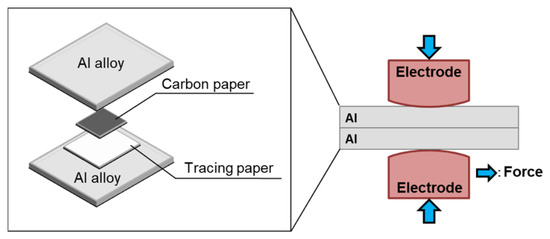
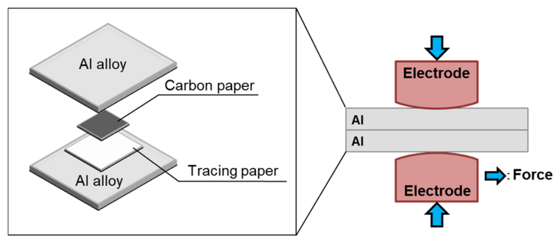
To investigate changes in the contact state as the electrode force varies, the contact area between two sheets was measured using carbon paper and tracing paper. A schematic diagram of this setup is shown in Figure 1. As shown in the figure, the two sheets are pressed together by the electrodes using the respective electrode forces. In this process, pressure is applied to the carbon paper and tracing paper placed between the plates; as a result, carbon from the carbon paper is transferred to the tracing paper, allowing the contact area to be measured.
Figure 1.
Evaluation method for the contact area between sheets when the applied electrode force is varying.
2.4. Measuring Method of Nugget Size
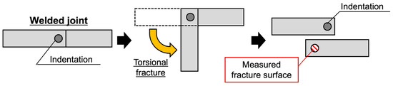
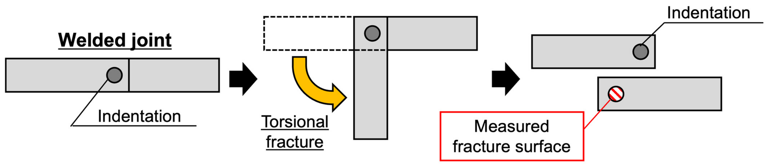
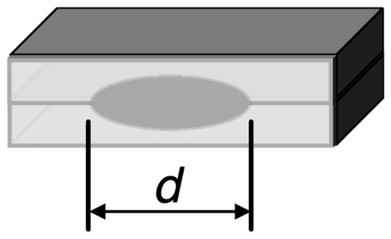
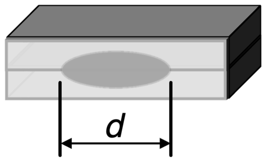
Figure 2 and Figure 3 show schematic diagrams of the methods used to measure the nuggets. First, as shown in Figure 2, the shape of the nuggets was determined by torsion-rupturing the welded sheets, thereby examining the nugget marks formed at the sheet interfaces. Furthermore, as shown in Figure 3, the nugget diameter was measured by performing macroscopic cross-sectional observations of the welded joints.
Figure 2.
Evaluation method for nugget shape observed at the interface between sheets.
Figure 3.
Evaluation method for nugget diameter observed from the cross-section of a joint.
2.5. Measuring Method of Electrode Wear
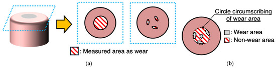
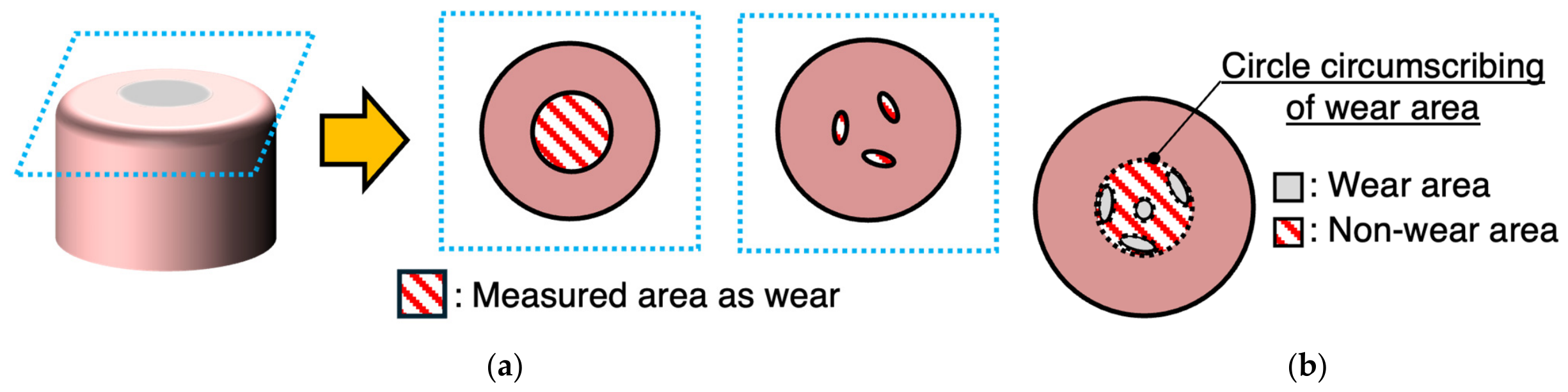
The wear condition of the electrodes was measured as shown in Figure 4. First, wear was assessed by observing the condition of the electrode surface; all areas exhibiting wear—including those with aluminum deposits and pitting—were included in the measurement as wear areas. Furthermore, the non-worn areas were also measured. The non-worn area was defined as the area obtained by subtracting the area of the wear area from the area of a circle circumscribing the wear area. By measuring this non-wear area during continuous welding experiments, it was possible to investigate the formation process of electrode wear, which typically occurs in a circular pattern.
Figure 4.
Evaluation method for electrode wear: (a) Evaluation method for electrode wear area; (b) Evaluation method for the non-wear area of an electrode based on an encircling circle in relation to electrode wear.
3. Results and Discussion
3.1. Changes in Contact Area Due to Changes in Electrode Force
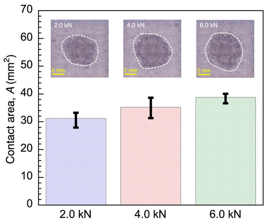
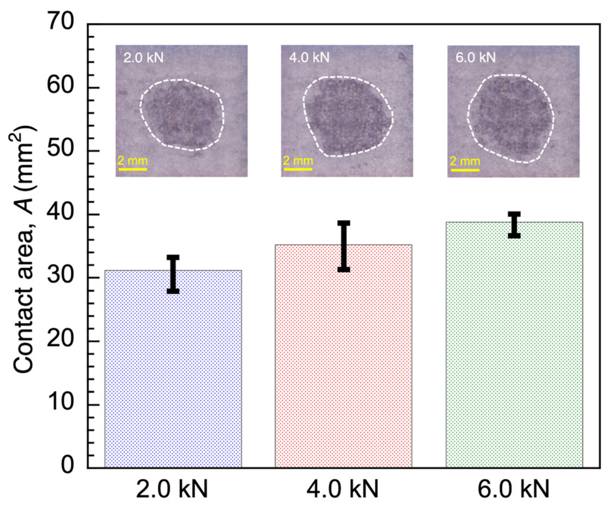
Figure 5 shows the results of observations of tracing paper after the application of pressure under each condition, as well as the measured contact areas. The outer perimeter of the contact area is indicated by a white dashed line. The figure shows that the contact area between the sheets decreases as the applied electrode force decreases. Furthermore, it was observed that the contact area decreases with decreasing electrode force.
Figure 5.
Measurement results for the applied electrode force and the contact area between sheets.
3.2. Changes in Nugget Size Due to Changes in Electrode Force
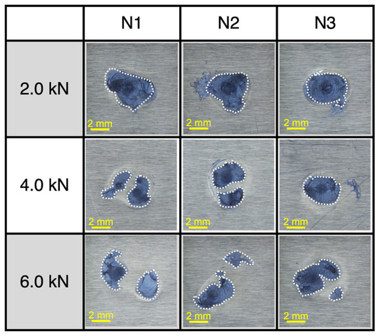
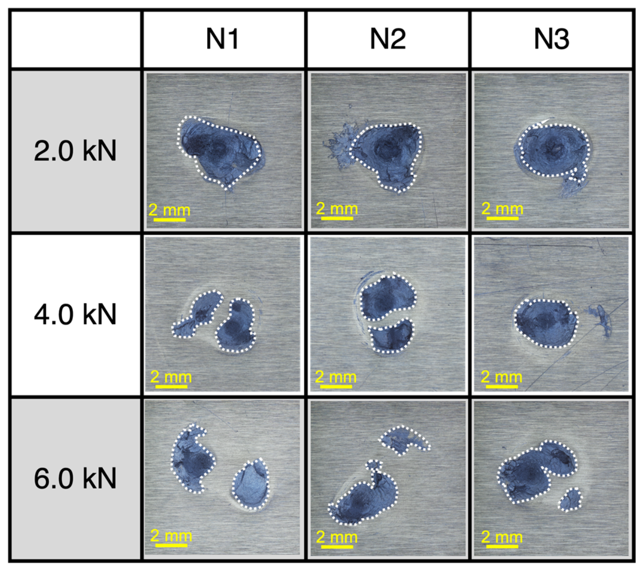
Figure 6 shows the formation state of the nugget at the interface between the sheets after a 5 ms current application time. As shown in the figure, under electrode force of 4.0 kN, the nuggets in two of the three joints are formed as separate nuggets, while one is formed as a single merged nugget. On the other hand, in the joints where the electrode force was reduced to 2.0 kN, the nuggets are formed as a single merged nugget in all joints. Conversely, when the electrode force was increased to 6.0 kN, the nuggets are formed as separate nuggets in all joints.
Figure 6.
Shape of the nugget formed at the plate interface when the current application time is 5 ms.
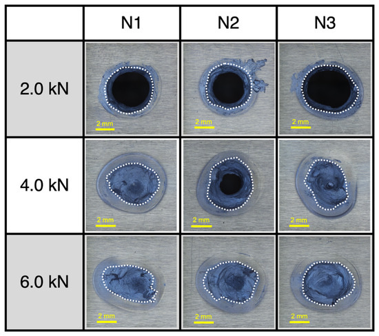
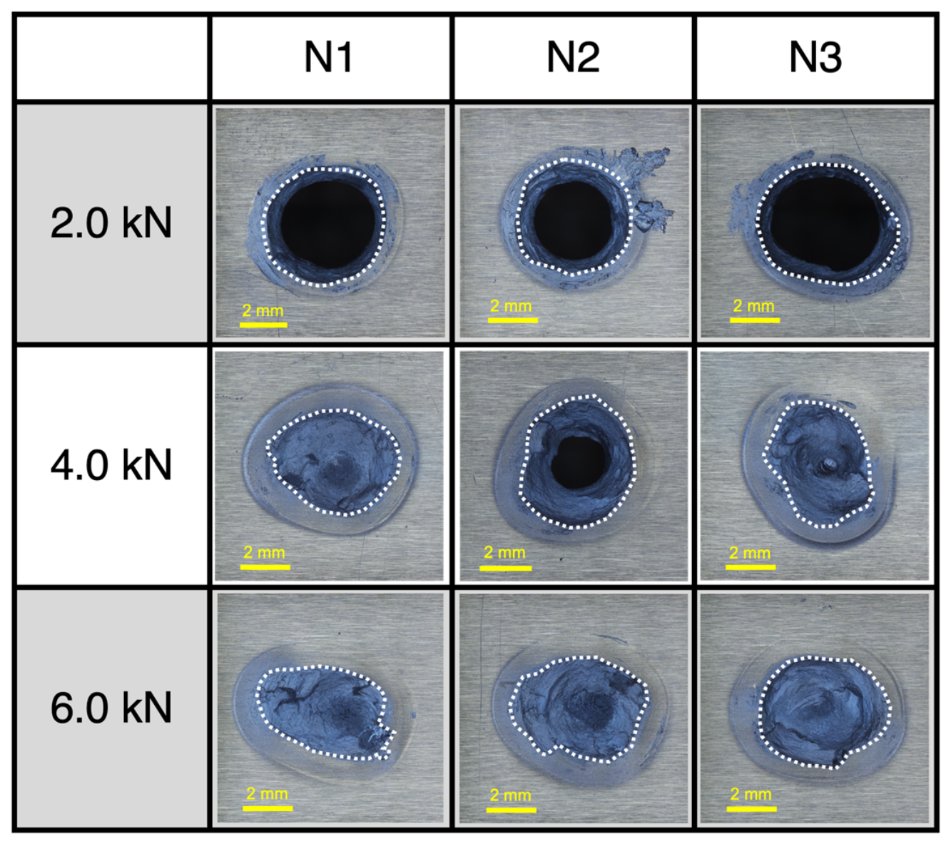
Next, Figure 7 shows the formation of the nugget at the joint interface of a joint subjected to a 100 ms current pulse. Under an electrode force of 4.0 kN, the nugget is not circular but elliptical in shape, and it is also flattened both horizontally and vertically. Furthermore, even under a higher electrode force of 6.0 kN, the nugget is similarly flattened into an elliptical shape. However, under the condition where the applied electrode force was reduced to 2.0 kN, the nugget formed into a relatively circular shape, indicating that the flattening had been improved. It is well known that the oxide film present on the surface of aluminum alloys affects nugget formation during resistance spot welding of these alloys. Because the oxide film has high electrical insulation properties, it constitutes a factor that inhibits nugget formation when current is applied during resistance spot welding; therefore, the oxide film must be broken down in order to form a nugget between the aluminum alloy sheets. However, during resistance spot welding, the destruction of the oxide film between aluminum alloy sheets occurs only locally within the area subjected to pressure from the electrodes. Consequently, separated nuggets, as shown in Figure 6, are formed. However, by reducing the electrode force (e.g., to 2.0 kN) to decrease the contact area, as shown in Figure 5, the area where localized destruction of the oxide film occurs shrinks; consequently, the nugget separation is suppressed, as shown in Figure 6. Furthermore, if nugget separation does not occur during the initial stage of current application (e.g., 5 ms), the nuggets are expected to grow stably during subsequent current application, resulting in the formation of nearly circular nuggets, as shown in Figure 7.
Figure 7.
Shape of the nugget formed at the plate interface when the current application time is 100 ms.
These results indicate that reducing the electrode force decreases the contact area between the sheets, thereby promoting localized current concentration and heat generation at the weld center during the initial stage of current flow. Consequently, stable nugget initiation is facilitated, which subsequently contributes to stable nugget growth during continuous welding.
Furthermore, the stable and circular nugget morphology obtained under the reduced electrode force condition is considered advantageous for improving the consistency of weld quality. In general, stable nugget formation contributes to reducing variation in the effective load-bearing area of spot-welded joints, which is expected to improve the consistency of joint performance. Although mechanical properties such as tensile shear strength were not evaluated in the present study, the observed stabilization of nugget morphology suggests the potential for improved joint reliability in practical manufacturing applications.
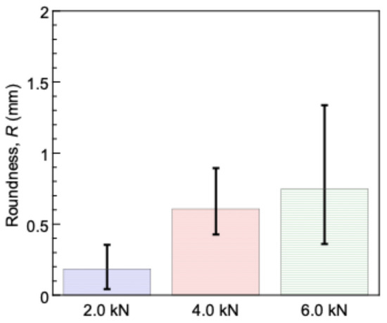
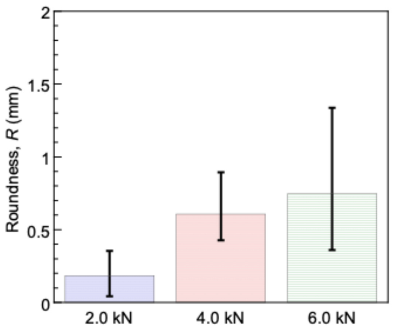
Therefore, the roundness of the nuggets was examined. Figure 8 shows the measurement results for the roundness of the nuggets under various electrode force conditions. As shown in the figure, these results suggest that the roundness of the nuggets increases as the applied electrode force decreases.
Figure 8.
Roundness of nugget diameter under varying electrode force conditions.
3.3. Continuous Welding with Electrode Force Changes and with and Without Pre-Welding
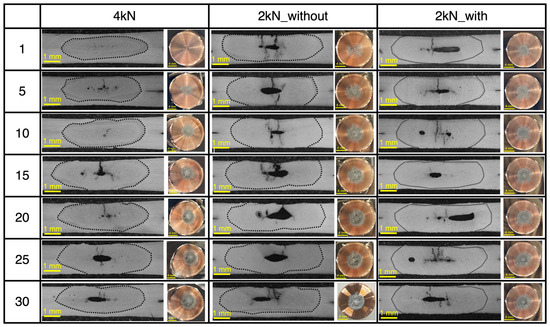
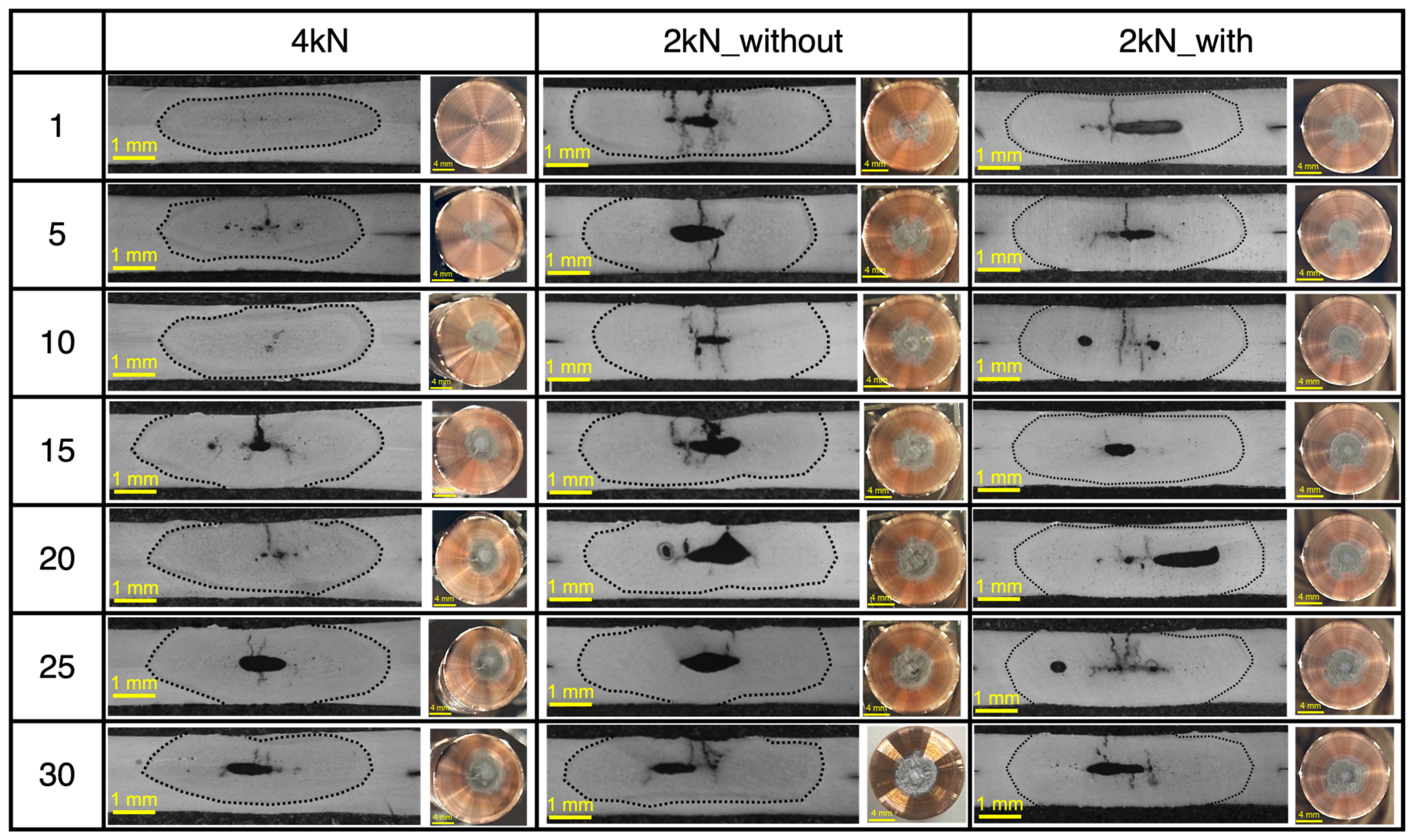
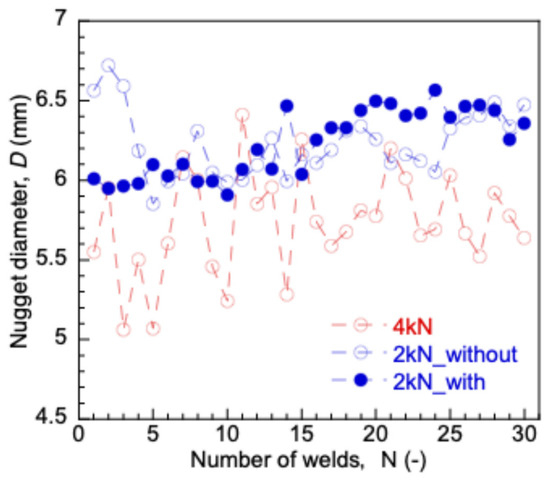
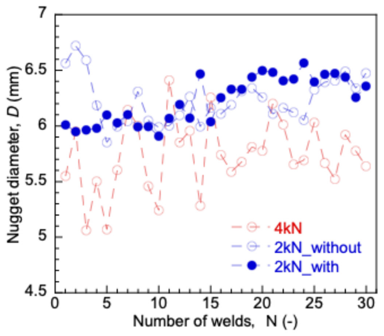
The results of the continuous welding experiments are shown in Figure 9. The figure shows cross-sectional photographs of the weld nugget and photographs of the electrode surface at each welding cycle. As shown in the figure, a weld nugget has formed in all joints, although its size varies slightly depending on the number of welding cycles. On the other hand, when examining the condition of the electrode surface, the degree of electrode wear increases with the number of welds as the number of weld time increases; however, it is not possible to clearly distinguish this difference from the photographs. Next, Figure 10 shows the relationship between the number of welds and the nugget diameter. The red data points in the figure represent the results for 4.0 kN, while the blue data points represent the results for 2.0 kN. Furthermore, the shaded data points represent the results obtained with pre-welding. First, comparing the results for 4.0 kN and 2.0 kN, the results indicate that under the 4.0 kN conditions, the nugget diameter exhibits a behavior of alternating between increasing and decreasing as the number of welds increases. Furthermore, up to approximately 10 weld times, the nugget diameter tends to increase gradually; thereafter, while alternating between increases and decreases, the nugget diameter tends to decrease gradually. Next, focusing on the 2.0 kN (without) condition, an excessively large nugget is formed when the number of welds is low. However, the nugget diameter then shrinks rapidly up to the fifth weld times, and thereafter, while alternating between gradual increases and decreases, the nugget diameter tends to increase gradually as the number of welds increases. These results indicate that, in the continuous welding experiments, the 2.0 kN condition exhibits less variation in nugget diameter compared to the 4.0 kN condition and consistently produces larger nuggets. However, under the 2.0 kN condition, excessively large nuggets are formed when the number of welds is low (e.g., up to the fifth weld times).
Figure 9.
Shape of the nugget cross-section and wear condition of the electrode surface as a change occurs in the applied electrode force and under conditions with and without pre-welding during continuous welding tests.
Figure 10.
Nugget diameter when varying the applied force and under conditions with and without pre-welding during continuous welding tests.
Therefore, focusing on the 2.0 kN with pre-welding condition (2.0 kN_with), the excessive nugget formation observed in the 2.0 kN_without condition is not seen; nuggets are formed stably even at low welding cycle counts, and while the nugget diameter subsequently tends to increase gradually, the variation in nugget diameter during this process is also small.
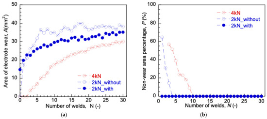
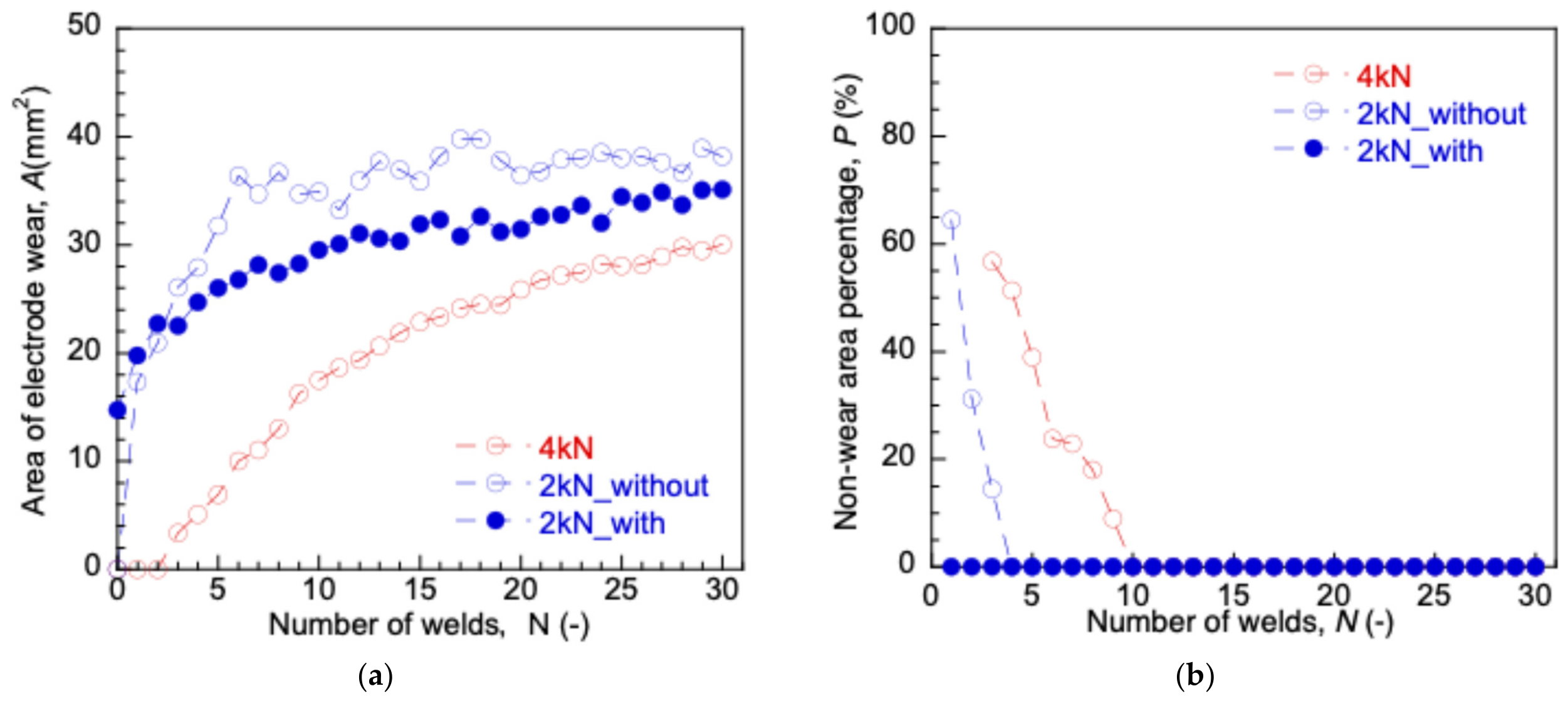
Next, Figure 11 shows the changes in the areas of electrode wear and non-wear, respectively. As shown in Figure 11a, the area of electrode wear increases with the number of welds under all conditions. However, the magnitude of this increase varies by condition. Under the 4.0 kN condition, no wear occurred during the first three welds, but electrode wear increased from the fourth to the tenth weld, and thereafter showed a gradual increase. In contrast, under the 2.0 kN_without condition, the area of wear increases rapidly up to the fifth weld times, but the increase thereafter is extremely gradual. Meanwhile, under the 2.0 kN_with condition, although the rate of increase in the area of wear is steep for the first few welds, it subsequently shows a gradual increase. Next, focusing on the area without wear shown in Figure 11b, a correlation with the aforementioned behavior of the increase in the wear area can be confirmed: under the 4.0 kN condition, the area without wear shrinks up to the tenth weld times, and under the 2.0 kN_without condition, the area without wear shrinks rapidly up to the fifth weld times. On the other hand, under the 2.0 kN_with condition, no unworn area was generated from the first weld. These results suggest that the process of wear significantly influences the tendency for the nugget diameter to increase. To describe in detail, when the electrode wear state is unstable—that is, when the area inside the circumscribed circle of the wear zone contains a mixture of wear and non-wear—nugget formation is unstable, leading to variation in nugget diameter; however, once the area inside the circumscribed circle is filled with wear, nugget formation becomes relatively stable. However, it can also be suggested that the number of welds required for the wear to stabilize affects the subsequent variation in nugget diameter. This can be attributed to the fact that not only simple wear due to the deposition of the aluminum alloy but also defects on the electrode surface, such as pores, influence nugget formation. Within the investigated experimental range, the reduced electrode force condition was effective for maintaining stable nugget formation during continuous welding. In addition, the results suggest that controlling the electrode wear morphology through appropriate pre-welding conditions is important for stabilizing the current path and maintaining process stability. Therefore, suppression of excessive enlargement of the contact area and promotion of uniform electrode wear are considered useful approaches for improving the continuous spot weldability of aluminum alloys in practical manufacturing processes. Although tensile shear testing was not conducted in the present study, this should be regarded as a limitation of the work. Since nugget diameter is generally related to the effective load-bearing area of spot-welded joints, the stabilization of the nugget diameter through the control of electrode wear morphology is expected to contribute to the improved consistency of joint performance. However, direct validation of the relationship between stabilized nugget formation and mechanical properties, including tensile shear strength and failure mode, remains a subject for future work.
Figure 11.
Electrode wear when varying the applied electrode force and under conditions with and without pre-welding during continuous welding tests: (a) Change in electrode wear area; (b) Change in electrode non-wear area.
4. Conclusions
In this study, electrode wear, which is a key factor influencing nugget formation, was investigated to improve the continuous spot weldability of aluminum alloys. The following results were obtained.
First, regarding the discussion on the formation of nuggets when the electrode force is varied, at the initial stage of current application, it was observed that as the applied electrode force increased, the nuggets tended to separate. Furthermore, under conditions where separated nuggets formed at the initial stage of current application, it was also observed that the nuggets tended to change from a circular to an elliptical shape after the current was applied. It can be concluded that this is due to changes in the contact area between the sheets accompanying changes in the applied electrode force, which caused the region where the oxide film—the starting point for nugget formation—is broken down to change.
Next, in the discussion of continuous welding under conditions involving variations in electrode force and the presence or absence of pre-welding, changes in electrode force and conditions with and without pre-welding caused variations in the trend of nugget diameter increase and in the variation in nugget diameter with each weld time. This indicates that the wear state of the electrode has a significant influence, specifically suggesting that stable nugget formation can be achieved when electrode wear progresses uniformly—that is, when aluminum alloy is deposited across the entire contact area between the electrode and sheet.
Author Contributions
Conceptualization, M.I.; methodology, M.I. and A.I.; validation, M.I. and A.I.; investigation, M.I. and A.I.; data curation, A.I.; writing—original draft preparation, M.I.; writing—review and editing, M.I.; visualization, A.I.; supervision, M.I.; project administration, M.I.; funding acquisition, M.I. All authors have read and agreed to the published version of the manuscript.
Funding
This research was supported by a research grant for the next generation of researchers from the Japan Welding Engineering Society.
Institutional Review Board Statement
Not applicable.
Informed Consent Statement
Not applicable.
Data Availability Statement
No new data were created or analyzed in this study. Data sharing is not applicable to this article.
Conflicts of Interest
The authors declare no conflict of interest.
References
- Miller, W.S.; Zhuang, L.; Bottema, J.; Wittebrood, A.J.; De Smet, P.; Haszler, A.; Vieregge, A. Recent development in aluminium alloys for the automotive industry. Mater. Sci. Eng. A 2000, 280, 37–49. [Google Scholar] [CrossRef] [Scilit]
- Hirsch, J. Recent development in aluminium for automotive applications. Trans. Nonferrous Met. Soc. China 2014, 24, 1995–2002. [Google Scholar] [CrossRef] [Scilit]
- Dursun, T.; Soutis, C. Recent developments in advanced aircraft aluminium alloys. Mater. Des. 2014, 56, 862–871. [Google Scholar] [CrossRef] [Scilit]
- Gould, J.E. Joining aluminum sheet in the automotive industry—A 30 year history. Weld. J. 2012, 91, 23s–34s. [Google Scholar]
- Zhang, H.; Senkara, J. Resistance Welding: Fundamentals and Applications; CRC Press: Boca Raton, FL, USA, 2011. [Google Scholar]
- Abe, Y.; Kato, T.; Mori, K. Self-piercing riveting and mechanical fastening in automotive applications. J. Mater. Process. Technol. 2009, 209, 3914–3922. [Google Scholar] [CrossRef] [Scilit]
- Dickinson, D.W.; Franklin, J.E.; Stanya, A. Characterization of spot welding behavior of aluminum alloys. Weld. J. 1980, 59, 170s–176s. [Google Scholar]
- Brechelt, S.; Müller, M.; Wagner, G. Diffusion barriers for electrodes in aluminum resistance spot welding. Surfaces 2025, 8, 81. [Google Scholar] [CrossRef] [Scilit]
- Nikitin, A.; Turabov, D.; Ermilova, E.; Evdokimov, A.; Ossenbrink, R.; Seidlitz, H. Using dynamic resistance to predict electrode surface degradation in resistance spot welding of 5182 aluminum alloy. Weld. World 2025, 69, 449–458. [Google Scholar] [CrossRef] [Scilit]
- Rashid, M.; Medley, J.; Zhou, Y. Nugget formation and growth during resistance spot welding of aluminum alloy 5182. Can. Metall. Q. 2011, 50, 421–430. [Google Scholar] [CrossRef] [Scilit]
- Sun, X.; Stephens, E.V.; Khaleel, M.A. Effects of fusion zone size and failure mode on peak load and energy absorption of advanced high strength steel spot welds. Weld. J. 2007, 86, 18s–25s. [Google Scholar]
- Pouranvari, M.; Marashi, S.P.H. Critical review of automotive steels spot welding: Process, structure and properties. Sci. Technol. Weld. Join. 2013, 18, 361–403. [Google Scholar] [CrossRef] [Scilit]
- Hu, S.; Ma, Y.; Li, Y.; Lin, Z.; Haselhuhn, A.S.; Carlson, B.E. Comparison of the resistance spot weldability of AA5754 and AA6022 aluminum to steels. Weld. J. 2020, 99, 224s–238s. [Google Scholar] [CrossRef] [Scilit]
- Stavropoulos, P.; Sabatakakis, K. Quality assurance in resistance spot welding. Metals 2024, 14, 185. [Google Scholar] [CrossRef] [Scilit]

Disclaimer/Publisher’s Note: The statements, opinions and data contained in all publications are solely those of the individual author(s) and contributor(s) and not of MDPI and/or the editor(s). MDPI and/or the editor(s) disclaim responsibility for any injury to people or property resulting from any ideas, methods, instructions or products referred to in the content. |
© 2026 by the authors. Licensee MDPI, Basel, Switzerland. This article is an open access article distributed under the terms and conditions of the Creative Commons Attribution (CC BY) license.