1. Introduction
The demand for lightweight, high-performance structures has significantly increased in recent decades, particularly in transportation, civil engineering, and energy applications. Aluminum alloys have emerged as key materials due to their favorable strength-to-weight ratio, corrosion resistance, and recyclability. Among these, high-strength alloys such as EN AW-7020 are widely used in welded structures, including bridges, vehicles, and load-bearing frameworks.
However, welded aluminum components are inherently susceptible to fatigue damage, especially under cyclic loading conditions. This is primarily due to welding-induced microstructural changes, residual stresses, and geometric discontinuities [
1,
2]. These effects are particularly critical under low-cycle fatigue (LCF), where relatively high strain amplitudes lead to rapid damage accumulation and reduced service life.
The fatigue design of welded aluminum joints is typically based on the nominal stress concept and standardized S–N curves as defined in EN 1999-1-3 [
3]. These approaches use detail categories that account for geometric effects and typical weld imperfections. However, the influence of mean stress is treated in a simplified manner, limiting the applicability of these concepts in the LCF regime. In particular, the role of the stress ratio is not explicitly represented, even though it can significantly affect fatigue performance.
Against this background, the present study—building on the experimental investigations conducted in Mathias Rengstl’s dissertation [
4,
5]—examines the fatigue behavior of welded EN AW-7020 aluminum joints under constant amplitude loading with varying stress ratios. The objective is to quantify the influence of mean stress on fatigue strength and to evaluate the applicability of current design methods.
To this end, fatigue tests were carried out on butt welds and cruciform joints at different stress ratios. The obtained S–N curves are compared with the corresponding detail categories in EN 1999-1-3 [
3], and the implications for fatigue design are discussed.
2. Experimental Program and Methodology
2.1. Materials and Specimens
The investigation is based on an experimental program designed to characterize the fatigue performance of welded aluminum joints under controlled laboratory conditions. The selected material, EN AW-7020, is a precipitation-hardened aluminum alloy that is widely used in structural applications due to its high strength and good weldability.
The test specimens were designed to represent welded joints with realistic geometric and material characteristics. Particular emphasis was placed on capturing the behavior of the weld metal and the heat-affected zone (HAZ) because these regions are known to influence fatigue performance.
Two representative welded joint configurations were considered:
Butt joints (X-welds) with full penetration, and
Cruciform joints (K-welds) with load-carrying fillet welds.
All specimens were manufactured by manual metal inert gas (MIG) welding (process 131) under controlled conditions, using AlMg4.5MnZr filler material. All welding parameters are specified in the manufacturer’s welding procedure specification (WPS) [
6]. No post-weld treatment was applied so that the specimens reflect typical as-welded conditions encountered in engineering practice. Due to the manual welding process, the weld profile exhibits some geometric variability (see [
4], as well as
Section 3.4). To capture the detailed geometry, the samples were measured by laser scanning (according to [
4,
7]).
2.2. Fatigue Testing
Fatigue tests were performed under constant amplitude loading in the LCF regime. The range of load cycles investigated was approximately 103 to 105.
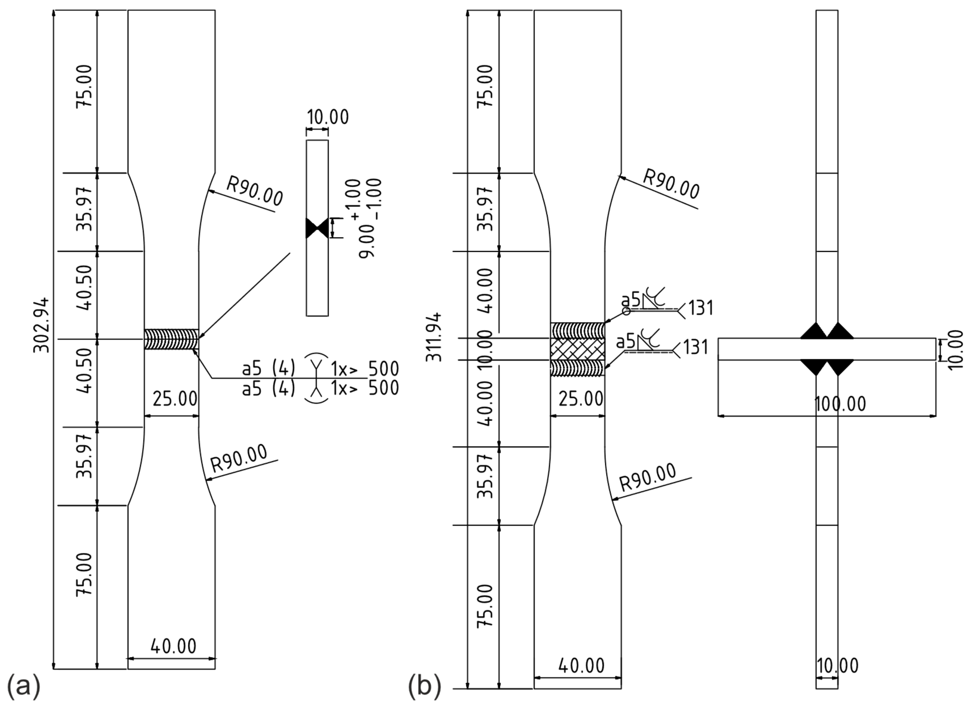
To evaluate the influence of mean stress, three different stress ratios were considered, and corresponding tests on cruciform and butt joints (specimen geometry, see
Figure 1) were conducted. The number of specimens indicates the number of valid results included in the analysis.
: 11 cruciform joints and 14 butt joints
: 13 cruciform joints and 22 butt joints
: 12 cruciform joints and 14 butt joints
The stress levels applied were selected so that failure would occur within the targeted LCF range. For higher stress ratios, the maximum applicable stress was limited by the tensile strength of the material. Failure was defined as the complete fracture of the specimen. The number of cycles to failure, Nf, was recorded for each test.
Figure 1.
Specimen geometry of (a) butt joint and (b) cruciform joint with dimensions in millimeters.
Figure 1.
Specimen geometry of (a) butt joint and (b) cruciform joint with dimensions in millimeters.
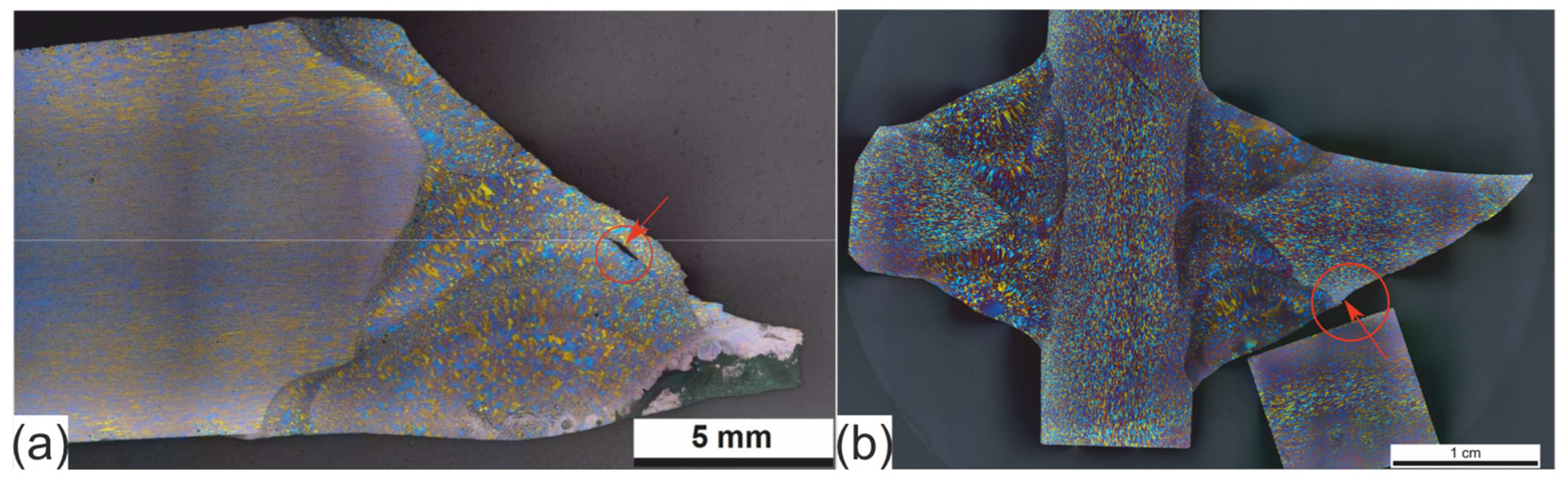
Crack initiation during fatigue loading predominantly occurred at the weld toe or in the transition region between the weld metal and the heat-affected zone.
Figure 2 shows the microstructure of two exemplary specimens with the positions of crack initiation.
Figure 2.
Microstructure and exemplary position of crack initiation of (
a) butt joint at fracture and (
b) cruciform joint [
4].
Figure 2.
Microstructure and exemplary position of crack initiation of (
a) butt joint at fracture and (
b) cruciform joint [
4].
2.3. Evaluation Method
The fatigue assessment was performed using the nominal stress approach, in accordance with EN 1999-1-3 [
3] and DIN 50100 [
8]. The experimental results were evaluated in terms of stress range (Δσ) versus number of cycles to failure (N
f) and were compared to the corresponding design S–N curves.
The following detail categories correspond to the tested specimens:
J.7.2.1 (50–4.3), J.7.2.2 (40–3.4), J.7.2.3 (36–3.4) for butt joints (X-welds) depending on the weld quality,
J.7.6 (36–3.4) for cruciform joints (K-welds).
According to EN 1999-1-3 [
3], Annex F, Table F.1, only Detail J.7.6 is permitted for design in the LCF range, regardless of the alloy. The experimental data were statistically evaluated using a two-sided 97.5% quantile, considering the entire set of samples [
3,
9,
10]. The resulting S–N curves were derived using the Basquin equation according to the background document 9.01a for fatigue design [
10] and directly compared to the respective design curves.
According to EN 1999-1-3 [
3], mean stress influence is considered using a correction factor, f(R). For the present case assumed (Annex G, Case 2), this factor is defined as f(R) = 1.0, independent of the applied stress ratio. Consequently, no mean stress correction is applied to the design curves, and identical fatigue resistance is assumed for all investigated R-ratios. The following section examines this assumption based on the experimental results.
3. Results and Discussion
3.1. Butt Joints (X-Welds)
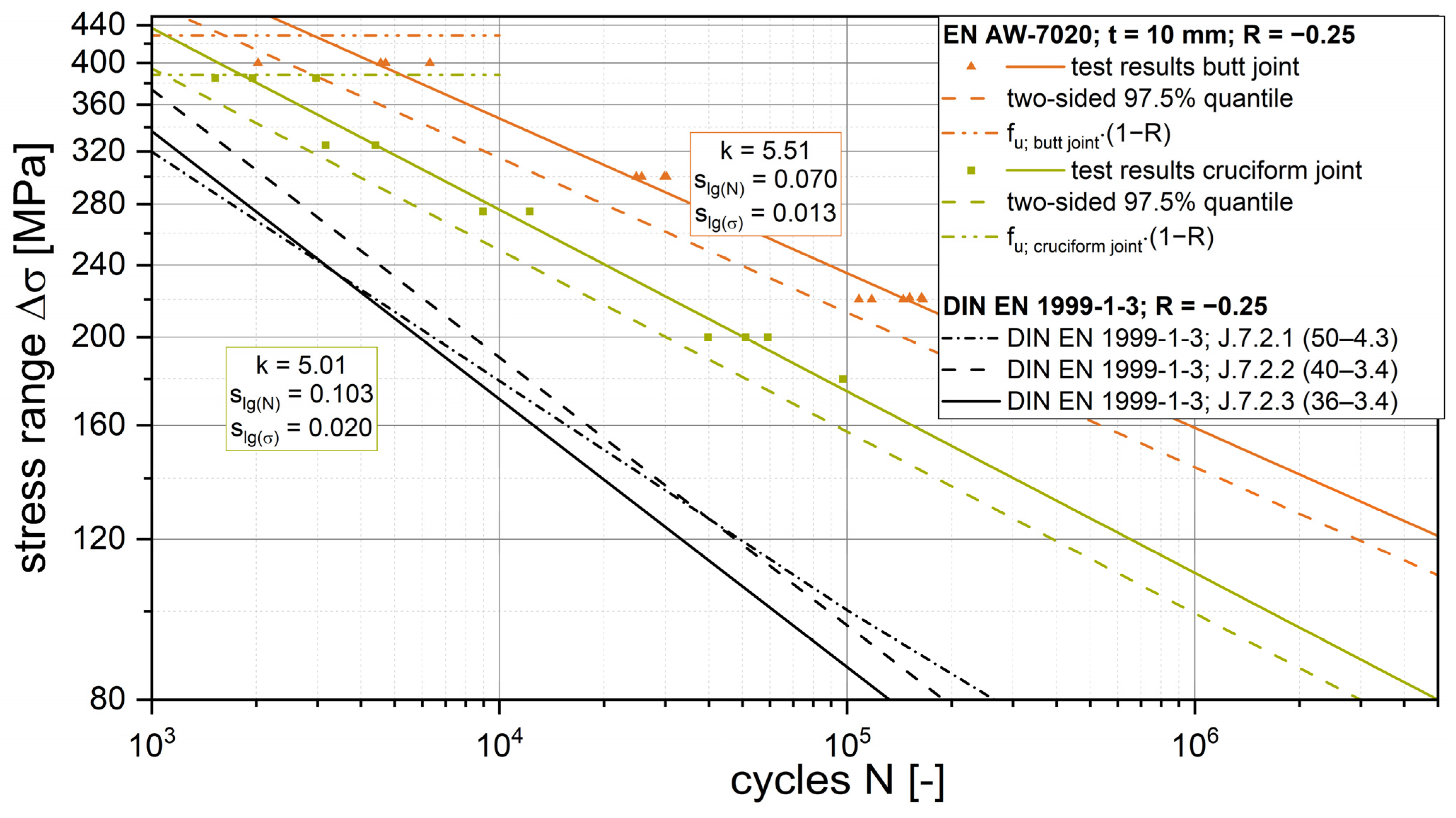
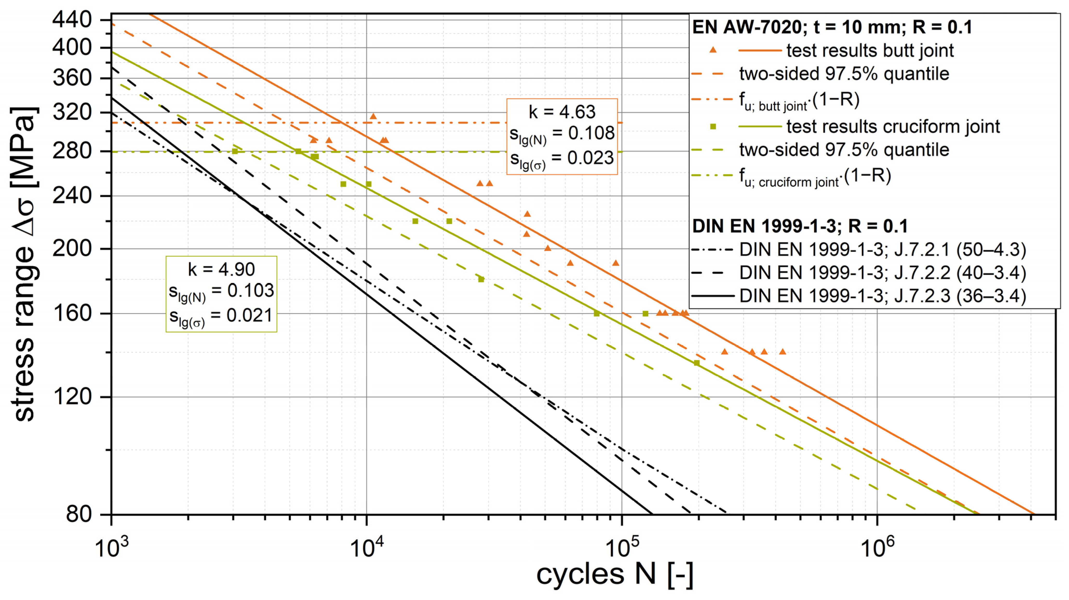
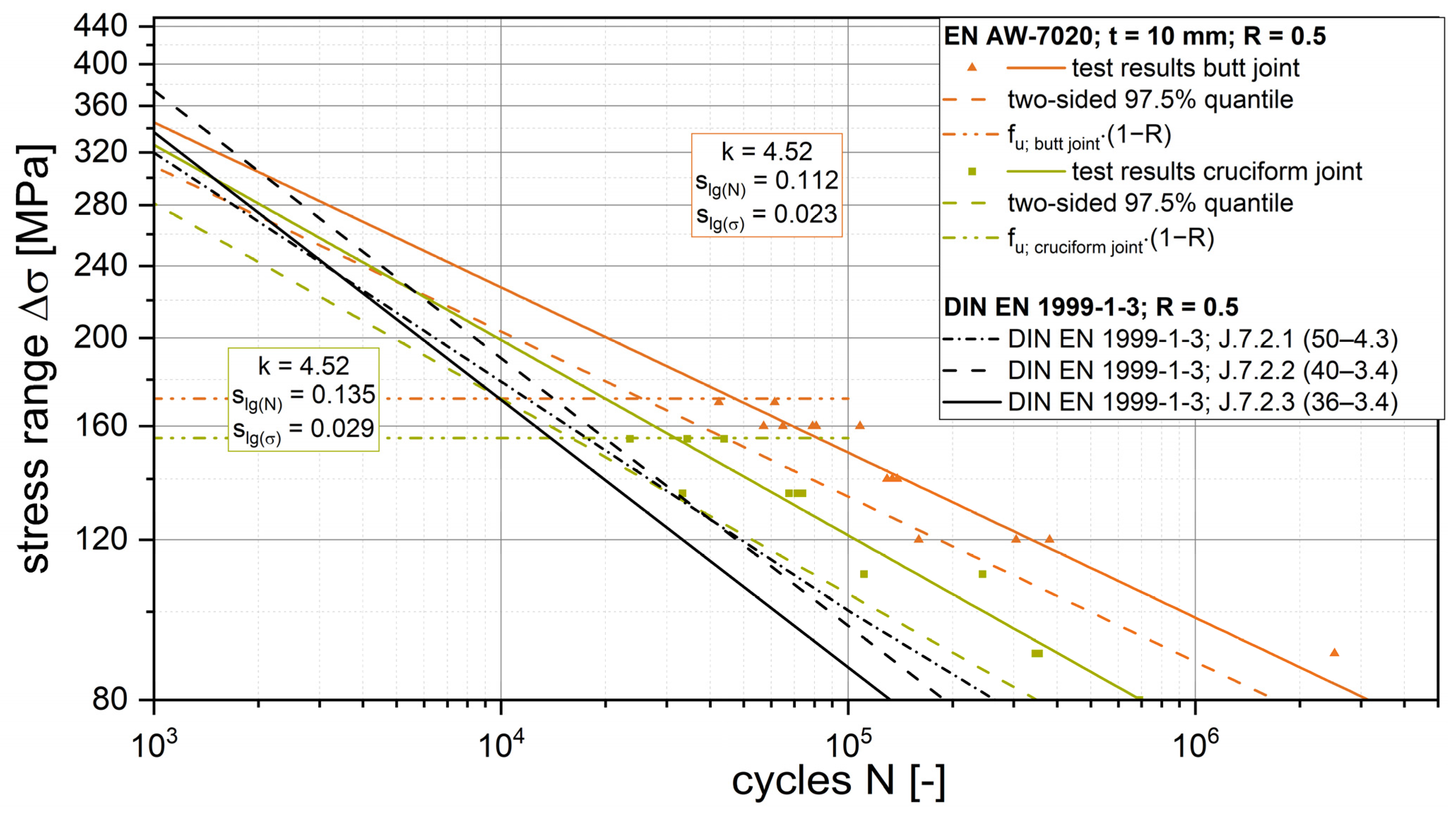
We evaluated the fatigue behavior of butt joints (X-welds) made of EN AW-7020 for different stress ratios. The corresponding S–N curves for R = −0.25, 0.1, and 0.5 are shown in
Figure 3,
Figure 4 and
Figure 5.
Figure 3 presents the experimental results for a stress ratio of R = −0.25. The derived 97.5% quantile S–N curve shows consistently higher fatigue strength than the design curve according to EN 1999-1-3 [
3], detail J.7.2.2. Even the higher notch class of detail J.7.2.1 could be reached.
In the low-cycle regime, the experimental data approach the upper stress limit defined by the tensile strength of the material. Consequently, failure occurs at relatively low cycle numbers, and the achievable stress range is limited by the material strength.
The slope of the experimental S–N curve is approximately k ≈ 5.5, steeper than the design slope m = 3.4. This indicates pronounced sensitivity of fatigue life to stress range in the investigated regime.
For a stress ratio of R = 0.1, a noticeable reduction in fatigue strength is observed (
Figure 4). The entire S–N curve shifts towards lower stress ranges compared to R = −0.25.
Despite this reduction, the experimental results remain predominantly above the design curve. However, the margin of conservatism is reduced, particularly in the transition between the low- and high-cycle fatigue regimes. The slope of the S–N curve (k ≈ 4.6) remains nearly unchanged for both stress ratios, indicating that the change in stress ratio primarily results in a vertical shift in the curve rather than a change in its inclination.
A further decrease in fatigue strength is observed at a stress ratio of R = 0.5 (
Figure 5) in combination with a further decrease in the slope (k ≈ 4.5). This reduction is most pronounced in the low-cycle regime, where maximum stress is limited by the material’s tensile strength. Nevertheless, the experimental S–N curve remains above the design curve throughout most of the investigated range. This suggests that the current design approach might be conservative for EN AW-7020, even at high stress ratios.
In summary, a clear influence of the stress ratio on fatigue performance can be identified. As R increases, fatigue strength systematically decreases over the entire range of load cycles. However, this effect is not considered in the design approach according to EN 1999-1-3 [
3], where a constant correction factor of f(R) = 1.0 is applied. Therefore, the experimental results indicate that the influence of mean stress on the fatigue behavior of welded EN AW-7020 joints is not negligible and should be considered in the design process.
3.2. Cruciform Joints (K-Welds)
The fatigue behavior of cruciform joints (K-welds) made of EN AW-7020 is evaluated in the same manner as butt joints. The corresponding S–N curves for different stress ratios are shown in
Figure 3,
Figure 4 and
Figure 5.
At R = −0.25, the experimental results for the cruciform joints consistently exceed the design curve according to EN 1999-1-3 [
3], detail J.7.6. The derived 97.5% quantile S–N curve indicates significantly higher fatigue strength than the code assumes. Compared to the butt joints, a similar slope (k ≈ 5.0) of the S–N curve is observed. Thus, the fatigue behavior is governed by a comparable sensitivity to stress range.
For R = 0.1, the S–N curve shifts towards lower stress ranges, indicating a reduction in fatigue strength. This trend is consistent with the observations made for the butt joints. Despite this reduction, the experimental curve remains above the design curve throughout the investigated range. Therefore, the conservatism of the design approach is maintained for this joint configuration.
A further decrease in fatigue strength is observed at a stress ratio of R = 0.5. However, the experimental S–N curve still exceeds the design curve within the relevant range of load cycles. The influence of the stress ratio is evident again, though the relative reduction in fatigue strength appears less pronounced than that of the butt joints.
The cruciform joint results confirm the trends observed in the butt joint results. Fatigue strength decreases with an increasing stress ratio, while experimental results consistently remain above the corresponding design curves. These results suggest a generally conservative design approach for EN AW-7020, regardless of the joint configuration.
3.3. Influence of Stress Ratio
The experimental results clearly demonstrate the significant influence of stress ratio R on the fatigue behavior of EN AW-7020 welded joints under constant amplitude loading. For both joint types investigated, a systematic reduction in fatigue strength is observed as the stress ratio increases. This effect is evident throughout the investigated range of load cycles, from the low-cycle regime up to approximately 106 cycles.
The stress ratio primarily influences the S–N curves by shifting them vertically, while the slope of the curves remains largely unchanged. This suggests that mean stress affects fatigue strength rather than the damage accumulation mechanism.
This behavior can be attributed to the local stress state at the weld toe and in the heat-affected zone. As the stress ratio increases, the mean stress level rises, resulting in a higher effective tensile stress during the loading cycle. This promotes crack initiation and accelerates crack propagation, thereby reducing fatigue life.
However, according to EN 1999-1-3 [
3], the influence of mean stress is disregarded in this case by assuming a constant correction factor of f(R) = 1.0. The same design curve is therefore applied regardless of the stress ratio. Nevertheless, the experimental results contradict this assumption. The reduction in fatigue strength identified with increasing R indicates that the mean stress effect is not negligible and should be considered in the fatigue assessment of welded aluminum structures.
At the same time, the experimental S–N curves for EN AW-7020 remain above the corresponding design curves for all investigated stress ratios. This suggests that the current design approach provides a conservative estimate of fatigue strength, even though the influence of the stress ratio is not explicitly accounted for.
3.4. Influence of Weld Geometry
In addition to fatigue testing, laser scanning techniques were used to investigate the geometry of the weld profiles. The measurements revealed significant variation in geometric parameters, especially the weld flank angle.
However, no clear correlation was identified between the measured weld geometry and the slope of the experimentally derived S–N curves. While geometric imperfections contribute to local stress concentrations, their influence on overall fatigue behavior could not be isolated using the nominal stress approach.
These findings suggest that variability in weld geometry alone cannot explain the observed differences in fatigue performance. Rather, the influence of the stress ratio appears to be the dominant factor governing fatigue behavior in the investigated regime.
It should be noted that the geometric data obtained from laser scanning was also evaluated in the context of structural and notch stresses. These approaches generally capture local effects and plasticity at weld notches better, particularly in the low-cycle fatigue regime (see [
4]). However, a detailed analysis using these methods is beyond the scope of this paper and will be addressed in future work.
4. Discussion
The experimental results clearly demonstrate that the fatigue performance of EN AW-7020 welded joints is significantly impacted by the applied stress ratio. Increasing the stress ratio from R = −0.25 to R = 0.5 systematically reduces the allowable stress range for a given number of cycles. This trend is not explicitly addressed in EN 1999-1-3 [
3], which treats the influence of mean stress in a simplified manner.
Compared to the standardized design curves, the experimental S–N data for EN AW-7020 consistently fall above the corresponding detail categories for both butt welds (J.7.2.2) and cruciform joints (J.7.6). This indicates that the current design approach is conservative for this alloy. However, the degree of conservatism varies depending on the stress ratio. This suggests that a uniform treatment of mean stress effects may be insufficient for welded aluminum structures.
Furthermore, the results highlight the limitations of the nominal stress concept when applied to welded joints in the low-cycle fatigue regime. The interaction of local stress concentrations, material inhomogeneities, and cyclic plasticity—particularly in the heat-affected zone—cannot be fully captured by nominal stress-based approaches. This contributes to the observed scatter and complicates the interpretation of fatigue behavior.
From a structural design perspective, the findings suggest that current design methods may be overly conservative for EN AW-7020 under certain loading conditions while lacking the ability to accurately capture stress ratio effects. Using experimentally validated fatigue data, such as that generated in this study, can improve fatigue assessment reliability. Another important outcome of the study was the integration of the experimental results into the Aluminum Fatigue Database (Alfabet) [
5]. For this study, the database was systematically revised and expanded by combining new experimental data with existing literature data. This approach provides a consistent, structured representation of fatigue properties for welded aluminum joints.
The resulting database provides accessible, validated data, facilitating the application of fatigue parameters in research and engineering and supporting the development of more refined, material-specific design approaches.
5. Conclusions and Outlook
This study examines the low-cycle fatigue behavior of welded EN AW-7020 aluminum joints subjected to constant-amplitude loading with varying stress ratios. The results demonstrate that fatigue performance clearly depends on the applied stress ratio; increasing mean stress reduces fatigue strength.
For both butt welds and cruciform joints, the experimentally determined S–N curves lie above the corresponding design curves according to EN 1999-1-3 [
3], suggesting that the design approach is generally conservative for this alloy. However, the current standard does not adequately represent the influence of the stress ratio.
Additionally, the findings highlight the limitations of the nominal stress concept in the low-cycle fatigue regime, where local effects in the heat-affected zone and cyclic plasticity play significant roles.
The results presented here contribute to an improved understanding of fatigue behavior in welded aluminum joints. The derived fatigue parameters were systematically integrated into the Aluminum Fatigue Database (Alfabet), which was expanded and updated in this study by combining new experimental results with existing literature data. This provides a consistent and accessible basis for more accurate fatigue assessments and supports developing refined, material-specific design approaches.
Future work should focus on expanding the experimental database and developing design methods that more precisely account for mean stress effects and local material behavior.
Author Contributions
Conceptualization, C.R., D.S. and J.B.; methodology, M.R.; software, M.R.; validation, M.R., D.S. and C.R.; formal analysis, M.R. and J.B.; investigation, M.R. and J.B.; resources, M.R.; data curation, M.R.; writing—original draft preparation, C.R. and D.S.; writing—review and editing, D.S. and J.B.; visualization, D.S. and J.B.; supervision, C.R.; project administration, M.R. and C.R.; funding acquisition, C.R. All authors have read and agreed to the published version of the manuscript.
Funding
This research was funded by IGF/Stifterverband Metalle, IGF 18629/N1.
Institutional Review Board Statement
Not applicable.
Informed Consent Statement
Not applicable.
Data Availability Statement
The data in ALFABET 2.0 are available via request. The raw data supporting the conclusions of this article will also be made available by the authors on reasonable request.
Conflicts of Interest
The authors declare no conflicts of interest.
References
- Hobbacher, A.F.; Baumgartner, J. Recommendations for Fatigue Design of Welded Joints and Components; IIW Collection; Springer Cham: Switzerland, 2024. [Google Scholar]
- Maddox, S.J. Fatigue Strength of Welded Structures; Woodhead Publishing: Cambridge, UK, 1991. [Google Scholar]
- EN 1999-1-3; Eurocode 9: Design of Aluminium Structures–Part 1–3: Structures Susceptible to Fatigue, German Version DIN EN 1999-1-3:2024. DIN German Institute for Standardization: Berlin, Germany, 2024.
- Rengstl, M. Welded Joints of Alloy AA7020 with Quasi-Static and Variable Loading in Context of Low Cycle Fatigue of DIN EN 1999-1-3. Ph.D. Thesis, Technical University of Munich, Chair of Metal Structures, Munich, Germany, 2024. [Google Scholar]
- Mensinger, M.; Radlbeck, C.; Rengstl, M. Neubewertung und Ergänzung der Versuchsdaten zur DIN EN 1999-1-3 mit Fokus Auf dem Kurzzeitfestigkeitsbereich. Available online: https://cdn.prod.website-files.com/655b551b01553a978275f0e7/6616b002889b9fd3804de60c_IGF-18629N_Schlussbericht.pdf (accessed on 7 July 2026).
- Fehr, J.C. Schweißanweisung des Herstellers WPS; Kraus-Maffei Wegmann: Kassel, Germany, 2011. [Google Scholar]
- Siebert, D.; Maier, R.; Radlbeck, C.; Mensinger, M. Fatigue performance of aluminum butt joints under varying weld orientations, misalignments, and weld geometry effects. Weld. World 2026. [Google Scholar] [CrossRef] [Scilit]
- DIN 50100; Load Controlled Fatigue Testing-Execution and Evaluation of Cyclic Tests at Constant Load Amplitudes on Metallic Specimens and Components, German version DIN 50100:2022. DIN German Institute for Standardization: Berlin, Germany, 2022.
- Kuhlmann, U. (Ed.) Background Documentation 9.01a: Background Information on Fatigue Design Rules-Statistical Evaluation. Unpublished. European Convention for Constructional Steelwork; ECCS, General Secretariat: Brussels, Belgium, 2017; Volume 119. [Google Scholar]
- Brozzetti, J.; Hirt, M.A.; Ryan, I.; Sedlacek, G.; Smith, I.F.C. (Eds.) Background Documentation 9.01a: Background Information on Fatigue Design Rules-Statistical Evaluation; ECCS, General Secretariat: Brussels, Belgium, 1989. [Google Scholar]
| Disclaimer/Publisher’s Note: The statements, opinions and data contained in all publications are solely those of the individual author(s) and contributor(s) and not of MDPI and/or the editor(s). MDPI and/or the editor(s) disclaim responsibility for any injury to people or property resulting from any ideas, methods, instructions or products referred to in the content. |