


Abstract
The present article considers the feasibility of using 3D-printed patterns for sand casting applications. The patterns have been produced by FDM/FFF technology, and the casting process has been simulated in the specialized CAE software product ProCAST. A prototype series of castings has been produced for the purpose of experimentally validating the applicability of 3D-printed patterns in the sand casting process. The results obtained demonstrate the significant potential of 3D-printed patterns to streamline the technological process in the manufacture of foundry tooling equipment. The use of additive-manufactured patterns reduces the time required for their design and production and increases flexibility in the manufacture of prototypes or small series products. The result is more efficient production planning and a reduction in the overall time required to produce sand castings.
1. Introduction
Foundry production remains one of the main technological processes for producing metal parts with complex geometry. Among the various methods, sand casting continues to be widely used due to its relatively low cost, technological flexibility, and ability to produce both individual parts and small to medium-sized series. A key stage in this process is the manufacturing of pattern tooling, which determines the geometric accuracy, surface quality, and repeatability of the resulting castings. However, traditional methods of pattern manufacturing often require considerable time and resources. In recent years, additive manufacturing technologies have emerged as an effective alternative to traditional methods of manufacturing tooling [1].
In today’s engineering practice, rapid prototyping technologies are extensively used for the production of various tooling equipment for forming processes, mainly because they enable a significant reduction in tool manufacturing time [2,3,4,5,6]. FDM/FFF 3D printing finds widespread application in this industry, including injection molding, silicone mold casting, investment casting, thermoforming, and other forming technologies [7,8,9,10]. One of the emerging applications is the use of 3D-printed patterns for sand casting, which offers significant advantages in terms of design flexibility and reduced lead times [11,12,13]. Traditionally, patterns for sand casting are made from wood, metal or polyurethane, depending on the production volume and complexity of the replicated part [14]. While these methods can produce high-quality patterns, they often involve labor-intensive processes, long lead times, and high costs.
3D printing patterns for sand casting using FDM/FFF represents an easy and cost-effective method for creating patterns and performing subsequent iterations [15]. In combination with specialized CAE solutions for simulating the casting process, high-quality small-batch castings can be rapidly produced [16,17,18].
Based on these advantages, the present study focuses on the fabrication of sand casting patterns using FDM/FFF 3D printing, combined with CAE simulations to optimize the casting process. The aim of the research is to analyze the applicability of 3D printing using the FDM/FFF method for the production of patterns intended for sand casting, as well as to assess the potential of this technology for reducing the time required and the production costs for manufacturing pattern equipment.
The following section describes the materials, 3D printing parameters, and simulation methodology used to produce and evaluate prototype castings.
2. Materials and Methods
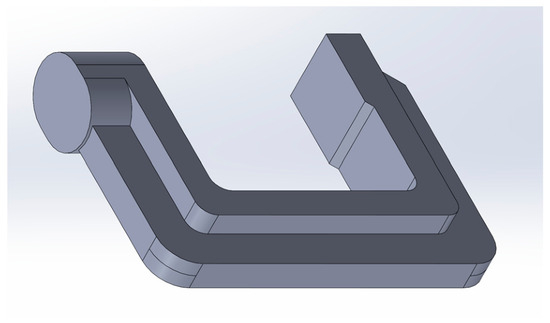
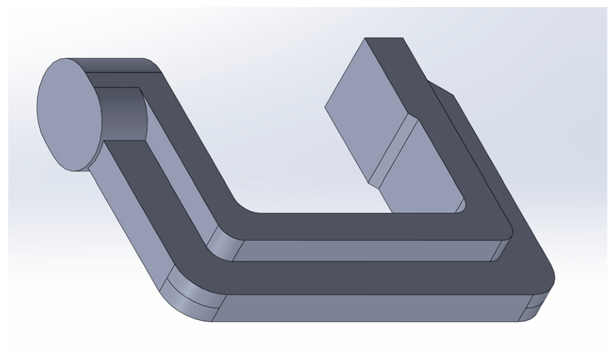
For the purpose of this study, a symmetric component—a part of a mounting fixture—is selected. Its 3D model, designed in the SolidWorks CAD v2022 environment, is shown in Figure 1.
Figure 1.
A part of a mounting fixture designed in SolidWorks.
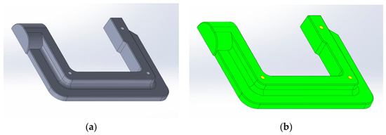
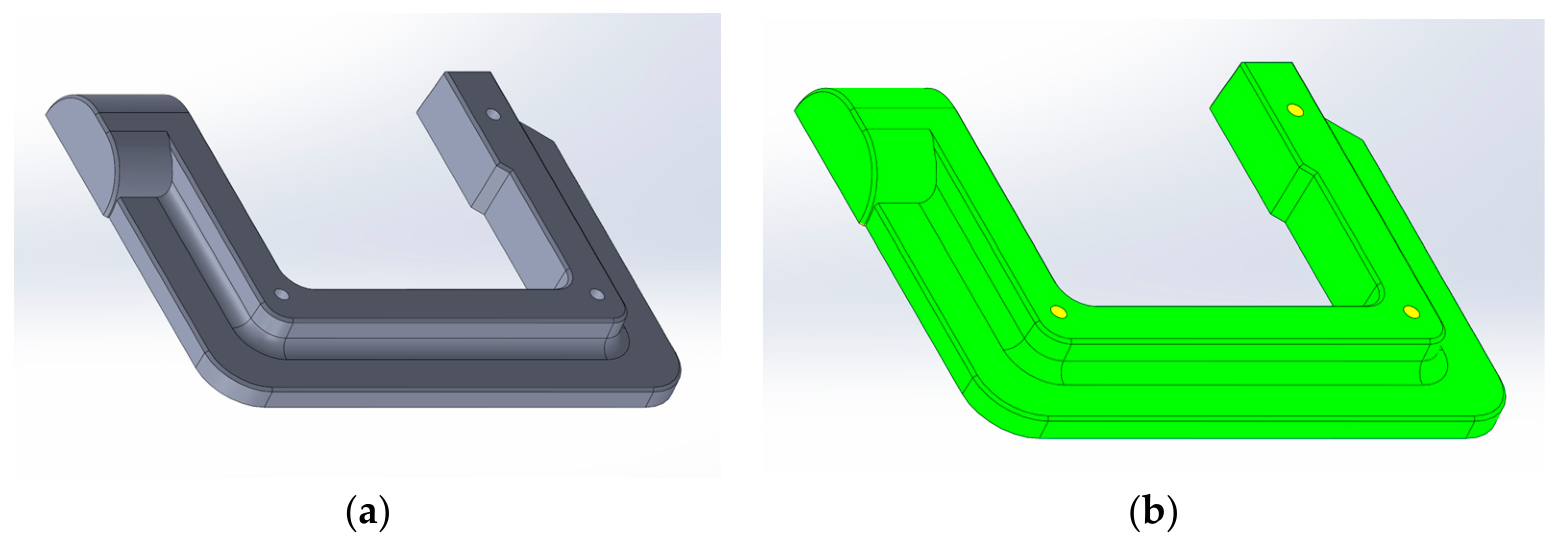
The created design is split in half to generate two symmetric patterns for sand casting. One-half is then selected, and draft angles between 3° and 5°, as well as filets, are applied. The 3D model is shown in Figure 2a. A draft analysis of the applied angles is performed using the draft analysis tool to verify that all walls have a minimum draft of 3°, thereby preventing defects and ensuring easy removal of the pattern from the sand mold. The result is shown in Figure 2b.
Figure 2.
(a) A 3D model with drafts and filets; (b) draft analysis.
The finalized symmetrical models are exported in IGES file format for use in the specialized CAE software ProCAST 2025.0. The following parameters are defined for the casting simulation:
- Pouring direction (gravity vector).
- Heat transfer coefficient ℎ for the metal–sand mold system: ℎ = 500 W/(m2K).
- Materials of the mold and casting: casting—EN AC–46400 (AlSi9Cu1Mg), mold—sand mold.
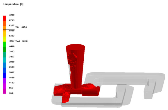
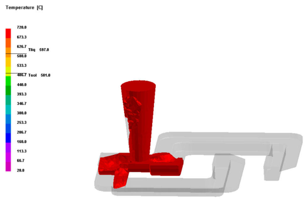
- Pouring temperature and mold temperature—pouring temperature—720 °C, sand mold—25 °C. Figure 3 shows the initial stage of the filling simulation in ProCAST.
Figure 3.
Initial stage of the filling simulation in ProCAST.
After validating the process in the virtual environment, the models are printed. For this purpose, both models are exported in STL format and loaded into the Bambu Studio slicer, where they are scaled by 3% to compensate for subsequent shrinkage during sand casting. The following printing settings are used:
- Printer: Bambu Lab X1C.
- Material: Sunlu PLA Marble.
- Nozzle diameter: 0.4 mm.
- Nozzle temperature: 220 °C.
- Bed temperature: 60 °C.
- Layer height: 0.12 mm.
- Line width: 0.42 mm.
- Wall loops: 5.
- Top shell layers: 5.
- Bottom shell layers: 5.
- Infill: 25% (Gyroid).
- Printing speed (outer wall): 60 mm/s.
- Printing speed (inner wall): 150 mm/s.
- Printing speed (infill): 180 mm/s.
- Printing speed (top surface): 150 mm/s.
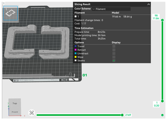
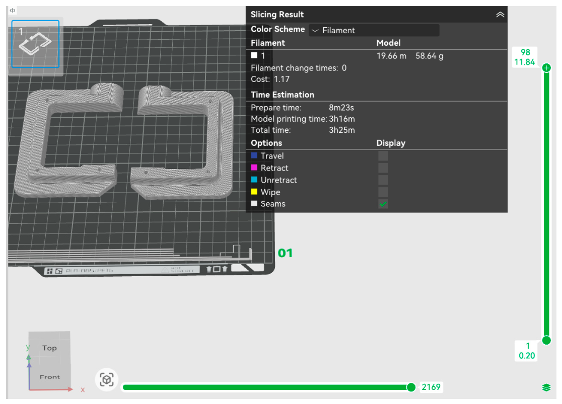
Figure 4 shows the parts in Bambu Studio after slicing. The figure displays the number of layers, material usage and the estimated printing time.
Figure 4.
Sliced view of the parts in Bambu Studio, showing the number of layers, material usage and estimated print time.
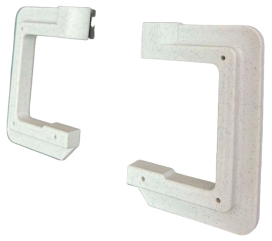
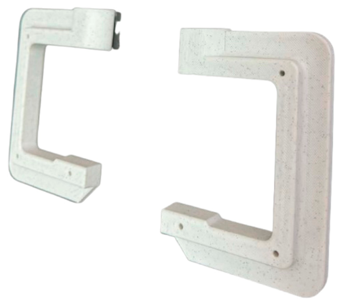
The printed parts are shown in Figure 5.
Figure 5.
3D-printed parts.
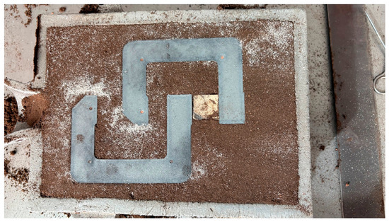
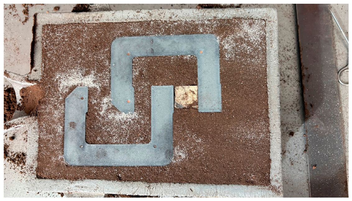
The next step involves placing the finished patterns into the sand mold and compacting it (Figure 6).
Figure 6.
Placement of the 3D-printed patterns in the sand mold prior to casting.
The following section presents the results obtained from the computer-aided simulations and from the casting experiment and discusses the effects of the 3D-printed patterns and simulation parameters on the quality of the produced castings.
3. Results and Discussion
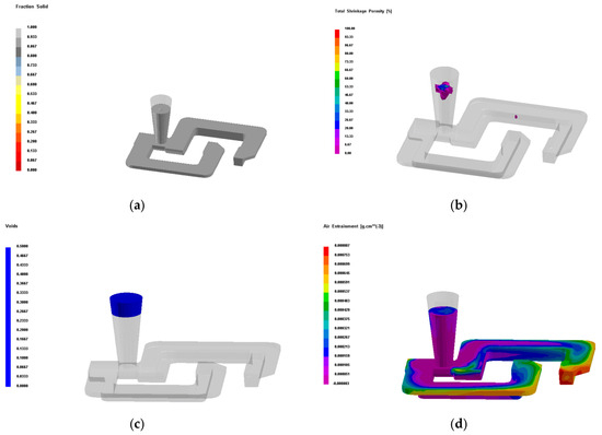
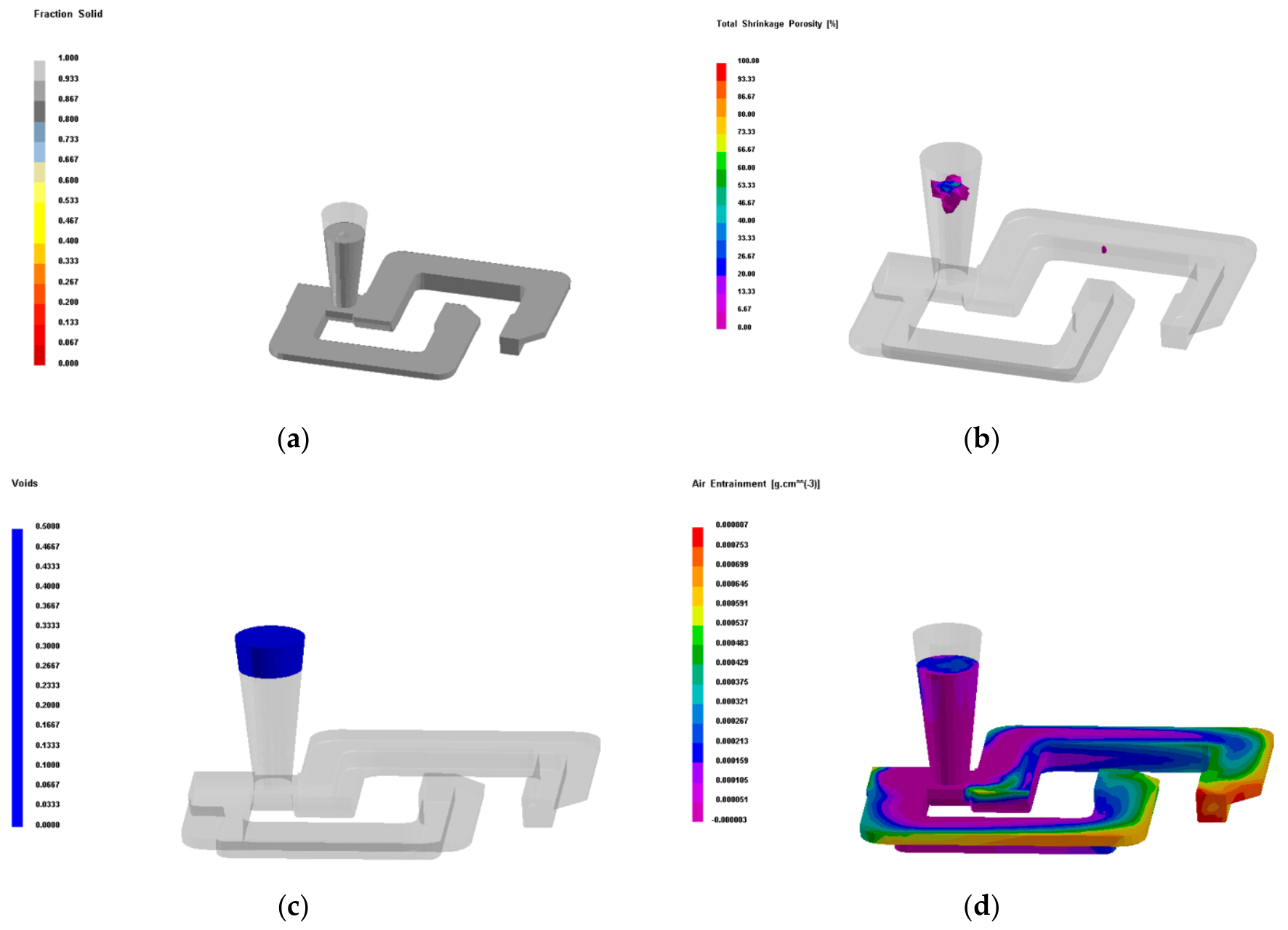
Figure 7 presents the results of the computer simulation.
Figure 7.
Results of the computer simulation: (a) casting crystallization—100%; (b) porosity due to shrinkage; (c) shrinkage voids in the casting; (d) air entrainment in the casting.
The castings at 100% crystallization are shown in Figure 7a, where good mold filling can be clearly observed. The shrinkage porosity is shown in Figure 7b. It is observed in the sprue and in negligibly small amounts in the castings. This indicates that the gating system and the mold filling conditions are defined within optimal limits for obtaining a high-quality casting. The results of the computer simulation regarding the formation of shrinkage cavities are shown in Figure 7c. The shrinkage void is localized in the sprue, which proves that the gating system has successfully fulfilled its function of feeding the casting. The results regarding the air entrainment are shown in Figure 7d, and they show that gas entrainment in the mold is possible; therefore, additional ventilation is recommended. The simulation results are satisfactory, allowing the actual casting of the parts to proceed.
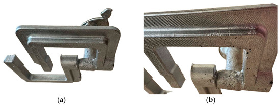
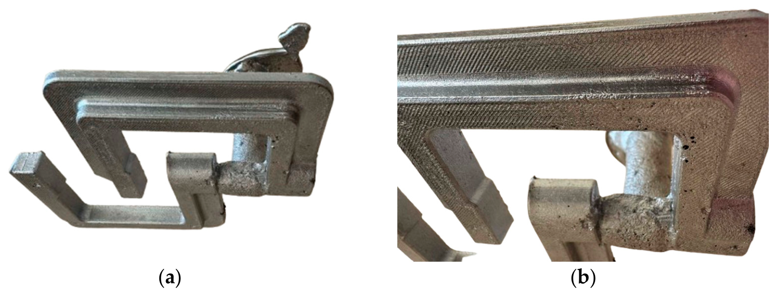
Figure 8a shows the cast parts along with the gating system and the sprue. Figure 8b provides a close-up view of the surface of the casting.
Figure 8.
(a) Cast parts with a gating system and sprue; (b) a close-up view of the surface of the casting.
From Figure 8a, it can be seen that the castings are of good quality and require minimal post-processing—removal of the gating system and some burrs—after which they can be used. In Figure 8b, the lines resulting from 3D printing of the top layers are clearly visible; these could be eliminated using the ironing function while printing the top layer.
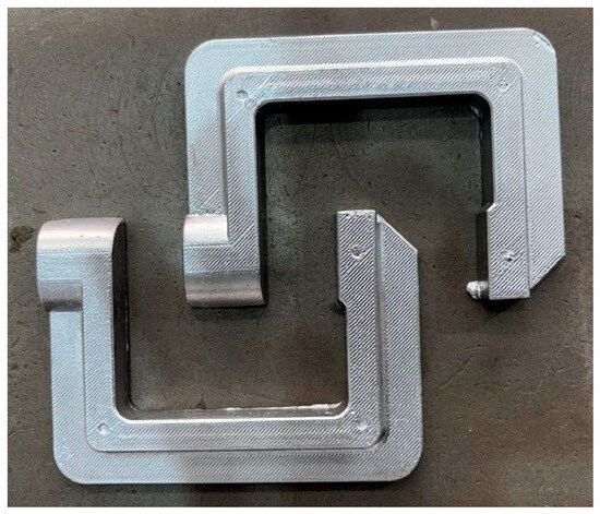
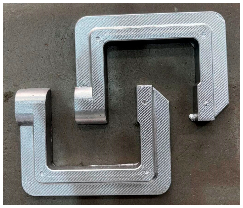
Castings cleaned of the gating system are shown in Figure 9.
Figure 9.
Castings after removal of the gating system.
4. Conclusions
This study demonstrates that FDM/FFF 3D printing, combined with CAE simulations, enables the rapid production of small-batch castings using sand molds. Parts produced using this approach are often more cost-effective than those manufactured through milling or metal 3D printing technologies and can be applied in a variety of industrial applications, including replacement components in machinery, supplementary fixtures for robotic systems, mounting devices, and many other applications.
Compared to traditional pattern-making methods, this approach offers enhanced design flexibility, shorter lead times and lower production costs.
The implementation of additive-manufactured patterns allows for more effective optimization of the detailed geometry and technological system as early as the initial development stage, which leads to improved casting quality and reduces the risk of manufacturing defects.
Author Contributions
Conceptualization, M.Z. and R.D.; methodology, M.Z. and K.P.; software, M.Z. and K.P.; validation, A.N.; formal analysis, A.N.; investigation, A.N.; resources, M.Z.; data curation, M.Z.; writing—original draft preparation, M.Z. and K.P.; writing—review and editing, R.D.; visualization, M.Z.; supervision, R.D.; project administration, M.Z.; funding acquisition, M.Z. All authors have read and agreed to the published version of the manuscript.
Funding
This work is supported by the program “Research, Innovation and Digitalization for Smart Transformation”, co-financed by the European Regional Development Fund. Grant Agreement No. BG16RFPR002-1.014-0014-C01, “Development and Sustainability Program with a Business Plan for a Laboratory Complex at Sofia Tech Park”.
Institutional Review Board Statement
Not applicable.
Informed Consent Statement
Not applicable.
Data Availability Statement
Data will be available on request.
Conflicts of Interest
The authors declare no conflicts of interest.
Abbreviations
The following abbreviations are used in this manuscript:
| CAD | Computer-aided Design |
| CAE | Computer-aided Engineering |
| FDM | Fused Deposition Modeling |
| FFF | Fused Filament Fabrication |
| IGES | Initial Graphics Exchange Specification |
| PLA | Polylactic Acid |
| STL | Stereolithography |
References
- Hawaldar, N.; Zhang, J. A Comparative Study of Fabrication of Sand Casting Mold Using Additive Manufacturing and Conventional Process. Int. J. Adv. Manuf. Technol. 2018, 97, 1037–1045. [Google Scholar] [CrossRef] [Scilit]
- Todorov, G.; Sofronov, Y.; Gavrilov, T.; Ivanov, I.; Todorov, A. Strategy for Shortened Manufacturing Cycle of Mold Tool in Extremely Short Terms. In Proceedings of the 30th International Scientific Symposium Metrology and Metrology Assurance, MMA 2020, Sozopol, Bulgaria, 7–11 September 2020; p. 9254249. [Google Scholar] [CrossRef] [Scilit]
- Pelin, G.; Sonmez, M.; Pelin, C.-E. The Use of Additive Manufacturing Techniques in the Development of Polymeric Molds: A Review. Polymers 2024, 16, 1055. [Google Scholar] [CrossRef] [Scilit] [PubMed]
- Dizon, J.R.C.; Valino, A.D.; Souza, L.R.; Espera, A.H.; Chen, Q.; Advincula, R.C. 3D Printed Injection Molds Using Various 3D Printing Technologies. Mater. Sci. Forum 2020, 1005, 150–156. [Google Scholar] [CrossRef] [Scilit]
- Chuchulska, B.; Dimitrova, M.; Dochev, B. In Vitro Study of the Surface Roughness, Hardness, and Absorption of an Injection-Molded Denture Base Polymer, Manufactured under Insufficient Mold Solidification. Appl. Sci. 2024, 14, 2906. [Google Scholar] [CrossRef] [Scilit]
- Parthiban, P.; Vijayan, S.; Doyle, P.S.; Hashimoto, M. Evaluation of 3D-Printed Molds for Fabrication of Non-Planar Microchannels. Biomicrofluidics 2021, 15, 024111. [Google Scholar] [CrossRef] [Scilit] [PubMed]
- Golubchikov, D.; Evdokimov, P.; Zuev, D.; Filippov, Y.; Shatalova, T.; Putlayev, V. Three-Dimensional-Printed Molds from Water-Soluble Sulfate Ceramics for Biocomposite Formation through Low-Pressure Injection Molding. Materials 2023, 16, 3077. [Google Scholar] [CrossRef] [Scilit] [PubMed]
- Todorov, T.; Bineva, K.; Romanov, B. Validation of Design and Ergonomics of a Protective Mask by Creating a Silicone Replication in a 3D Printed Mold Tool. Mech. Mach. Sci. 2025, 174, 335–344. [Google Scholar] [CrossRef] [Scilit]
- Ghaznavi, A.; Xu, J.; Hara, S.A. A Non-Sacrificial 3D Printing Process for Fabricating Integrated Micro/Mesoscale Molds. Micromachines 2023, 14, 1363. [Google Scholar] [CrossRef] [Scilit] [PubMed]
- Ráž, K.; Chval, Z.; Kořínek, J. Using a Model Created Using a 3D Printer to Mould a Grey Cast Iron Casting. Materials 2024, 17, 4033. [Google Scholar] [CrossRef] [Scilit] [PubMed]
- Upadhyay, M.; Sivarupan, T.; El Mansori, M. 3D Printing for Rapid Sand Casting—A Review. J. Manuf. Process. 2017, 29, 211–220. [Google Scholar] [CrossRef] [Scilit]
- Li, S.; Wu, X.; Yue, L. Application of 3D Sand Casting Technology for Inlet Duct Wind Tunnel Test Models. Eng. Proc. 2024, 80, 48. [Google Scholar] [CrossRef] [Scilit]
- Cecchel, S.; Cornacchia, G. Additive Manufacturing for Rapid Sand Casting: Mechanical and Microstructural Investigation of Aluminum Alloy Automotive Prototypes. Metals 2024, 14, 459. [Google Scholar] [CrossRef] [Scilit]
- Lehmhus, D. Advances in Metal Casting Technology: A Review of State of the Art, Challenges and Trends—Part II: Technologies New and Revived. Metals 2024, 14, 334. [Google Scholar] [CrossRef] [Scilit]
- Royan, M.; Arianto, L.S.; Sasongko, B.; Pradana, D. FDM 3D Printing Application for Making Plate Pattern on Sand Casting. J. Eng. Appl. Technol. 2023, 4, 67–77. [Google Scholar] [CrossRef] [Scilit]
- Dou, K.; Lordan, E.; Zhang, Y.J.; Jacot, A.; Fan, Z.Y. A Complete Computer Aided Engineering (CAE) Modelling and Optimization of High Pressure Die Casting (HPDC) Process. J. Manuf. Process. 2020, 60, 435–446. [Google Scholar] [CrossRef] [Scilit]
- Qin, S.; Lv, P.; Li, S.; Li, Y. Casting Process of Gate Valve Steel Based on ProCAST Simulation. J. Phys. Conf. Ser. 2021, 1798, 012013. [Google Scholar] [CrossRef] [Scilit]
- Matin, I.; Hadzistevic, M.; Vukelic, D.; Potran, M.; Brajlih, T. Development of an Expert System for the Simulation Model for Casting Metal Substructure of a Metal-Ceramic Crown Design. Comput. Methods Programs Biomed. 2017, 146, 27–35. [Google Scholar] [CrossRef] [Scilit] [PubMed]
Disclaimer/Publisher’s Note: The statements, opinions and data contained in all publications are solely those of the individual author(s) and contributor(s) and not of MDPI and/or the editor(s). MDPI and/or the editor(s) disclaim responsibility for any injury to people or property resulting from any ideas, methods, instructions or products referred to in the content. |
© 2026 by the authors. Licensee MDPI, Basel, Switzerland. This article is an open access article distributed under the terms and conditions of the Creative Commons Attribution (CC BY) license.