


Abstract
The threaded connections used in drilling machines operate under high axial loads and torques. These elements ensure both the reliable fastening of the drill heads and their centering relative to the other components of the structure. For fastening drill heads, threads with specific profiles are used, such as trapezoidal profiles with asymmetric flanks. A profile tool is typically used for manufacturing such profiles. This, in turn, limits the flexibility of the process and increases costs in small-batch and repair production conditions. This study proposes a methodology for machining a buttress thread, with trapezoid side angles of 5° and 45°, using a standard grooving insert. The profile geometry is described analytically through the height of each pass of the threading cycle and the inclination angles of the trapezoid flanks, and the implementation is carried out using a macro program based on synchronized G92 cycles. The final profile is formed by the superposition of helical surfaces with a constant pitch. The approach enables the realization of non-standard trapezoidal profiles without the need for a specially profiled tool. The proposed model serves as a foundation for subsequent research into the geometric accuracy and strength characteristics of the thread profile obtained by this method.
1. Introduction
Threaded Connections in Drilling Machines: Requirements, Challenges, and a Manufacturing Methodology for Buttress Threads.
Threaded fasteners are one of the most common machine elements in mechanical engineering [1,2]. In addition to their classic fastening functions, in modern mechanical engineering, they are also used as elements for motion conversion, force regulation, and displacement control [3,4]. Some of these functions lead to the necessity of using new, non-standard profiles and thread angles.
Threaded fasteners for mounting drill heads operate under significant axial loads, dynamic impacts, and cyclically varying stresses. In this type of assembly, threads do not only perform fastening functions but are also responsible for ensuring coaxial alignment, transmitting torque, and even controlling the torque [5]. This imposes higher requirements on geometric accuracy, load-bearing capacity, and the distribution of contact stresses along the length of the thread.
Classic trapezoidal threads are characterized by a symmetrical profile where the angles at the base are equal [6,7]. This symmetry guarantees an even distribution of force under bidirectional loading. However, this is not the optimal option in cases where there is predominantly unidirectional loading.
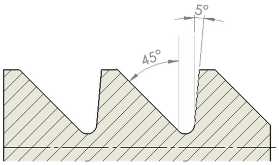
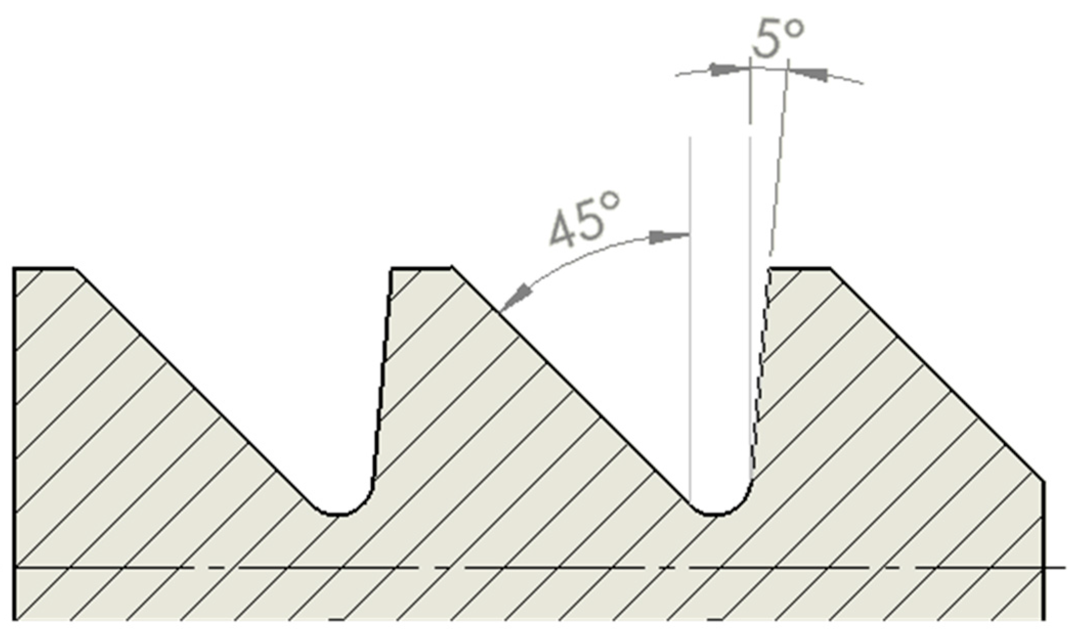
The aim of this article is to develop a methodology for machining a buttress thread using a standard grooving insert with a rectangular cross-section [8], as seen in Figure 1. Specifically, the buttress profile will have an angle of 5° on the loaded flank of the profile and 45° on the opposite flank [9]. In this way, the large angle on the loaded side of the profile ensures an increased contact area and better stress distribution. The thread pitch is constant along the axis of the component and equals 6 mm.
Figure 1.
Buttress thread.
Machining this thread requires the use of a specially developed tool—an insert manufactured according to a specific tooling technology [10]. This, in turn, makes costs high and minimizes the flexibility to reconfigure the technological system for a different type of thread. In the conditions of single-part production or the repair of existing assemblies, this is economically unjustified in most cases [11]. An alternative solution to this is to generate the profile using the so-called generating method, employing a standard grooving insert.
For generating a tool path for thread cutting, standard CNC machine tools use the so-called fixed cycles for thread cutting (G32, G76, G92). However, they lack the capability to account for and generate a cutting path for the specific characteristics of this type of thread, namely the different angles at the base of the profile. This is precisely the reason for the necessity of a profile tool for machining these threads.
2. Materials and Methods
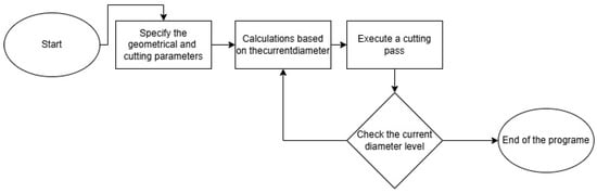
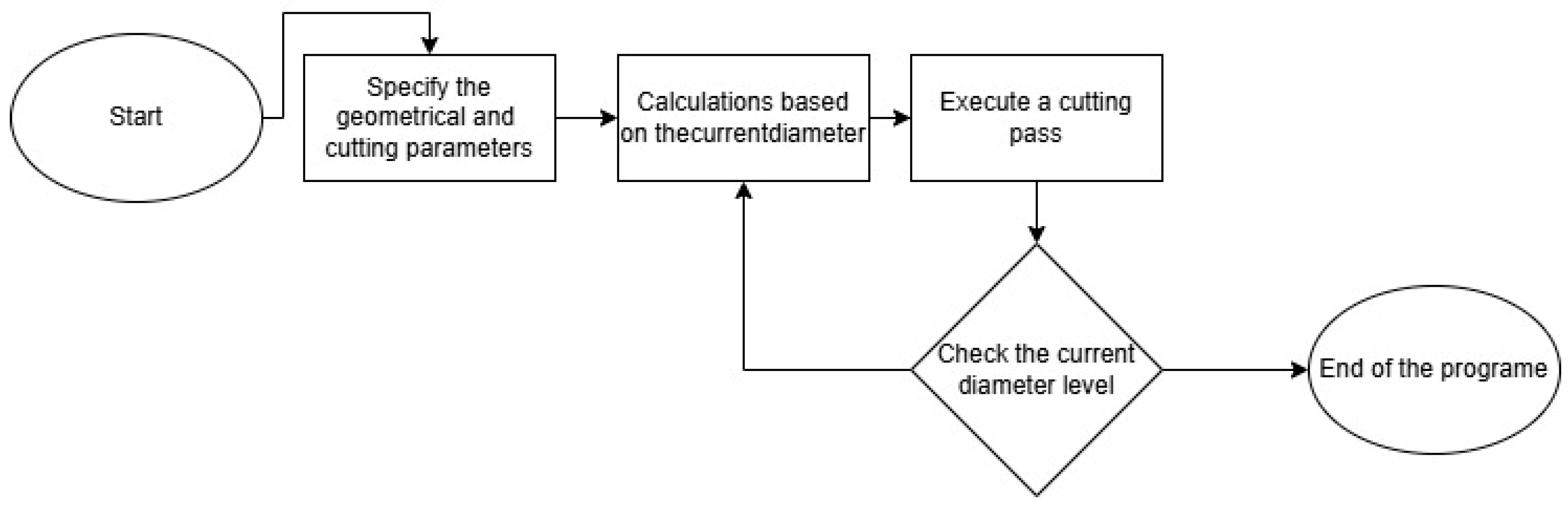
The methodology for developing the macro program is considered in three stages [12]. The first of these is the geometric model of the trapezoidal profile with asymmetric angles ( The geometry is defined in a longitudinal section, which corresponds to the X-Z plane on the lathe, where the X-axis denotes the diametrical dimensions (typical for standard ISO programming), and the Z-axis denotes the linear dimensions along the direction of the work piece axis [13]. The program structure is shown in Figure 2 in the form of a block diagram.
Figure 2.
Program structure.
The main input parameters for describing the profile geometry are the internal diameter , external diameter , the profile height , and pitch . At the beginning of the macro program, their values are set by the user and stored in registers with local macro variables as follows [14]:
To describe the asymmetric inclination of the sides of the trapezoidal profile, we use tangent functions of the form:
The axial offsets and for a given height h with different inclinations and are calculated according to the model:
Thus, based on this logic, the generation of the asymmetric trapezoidal profile is achieved, executed through multiple synchronized helical motions realized by the G92 cycle. The process can be described as an integrative approximation of the profile through a series of helical surfaces. An important aspect is the discretization along the X-axis, or in other words, along the diameter of the thread profile.
Assuming that the initial machining diameter is equal to the external diameter of the thread (11), and with (12) we define the depth of cut for each pass; then, the current diameter for each pass will be determined by Formula (13), and, respectively, the number of steps will be which can be calculated by Formula (14).
The starting point for each pass is calculated for each iteration in the coordinate system, for the right flank, using Equations (15) and (16):
The implementation of the motion is carried out with the following command line:
We perform analogous calculations for the entry points describing the trajectory of the left flank. For them, we use Equations (18) and (19).
The implementation of the motion is carried out with the following command line:
Table 1 summarizes the input data that the user must enter before running the program.
Table 1.
Input values of program.
Table 2 summarizes all calculations performed by the macro program during machining.
Table 2.
Parametric description of the formulas used.
3. Results
As a result of the proposed methodology, a macro program was developed. Using this program, experimental samples were machined—the formation of the desired profile can be observed, as well as profiles with different values of thread angles and diameters. For machining the samples, a CNC turning center was used with the following main parameters: main spindle power 11.2 kW and torque of 102.0 Nm at 1300 rpm, 6.5” chuck size, X-axis travel 200 mm, Z-axis travel 200 mm, and maximum axis load 10,676 N (Max Thrust) [15].
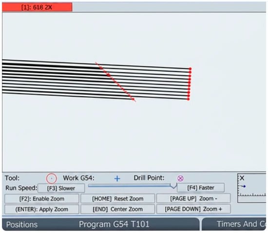
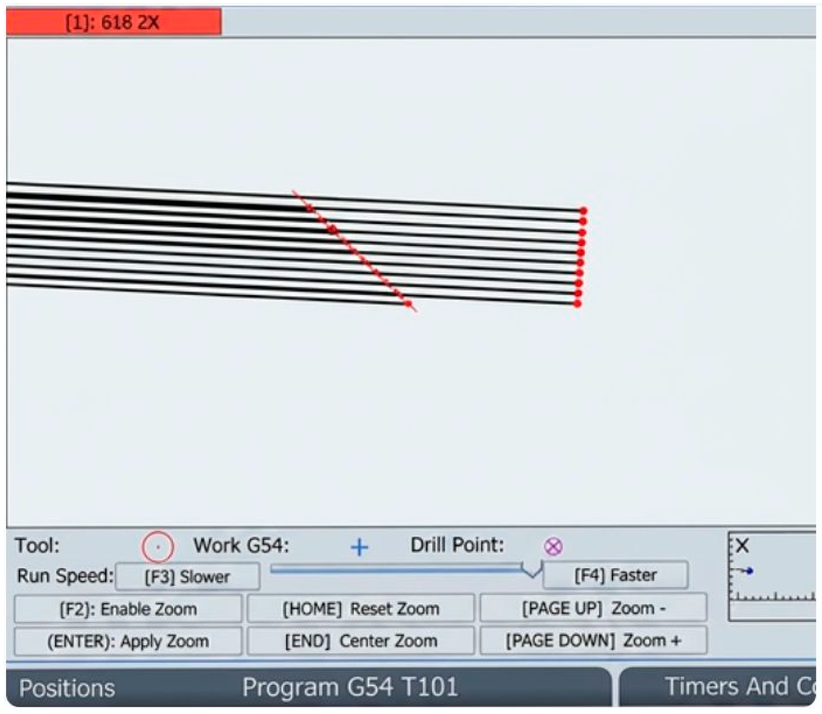
Figure 3 shows the starting points of the thread profile during program simulation.
Figure 3.
Profile figure.
The formation of the desired profile can be clearly seen through successive starting points beginning from the external diameter, which sequentially describes both flanks of the thread profile before moving to the next diametrical level.
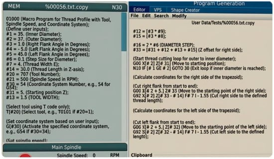
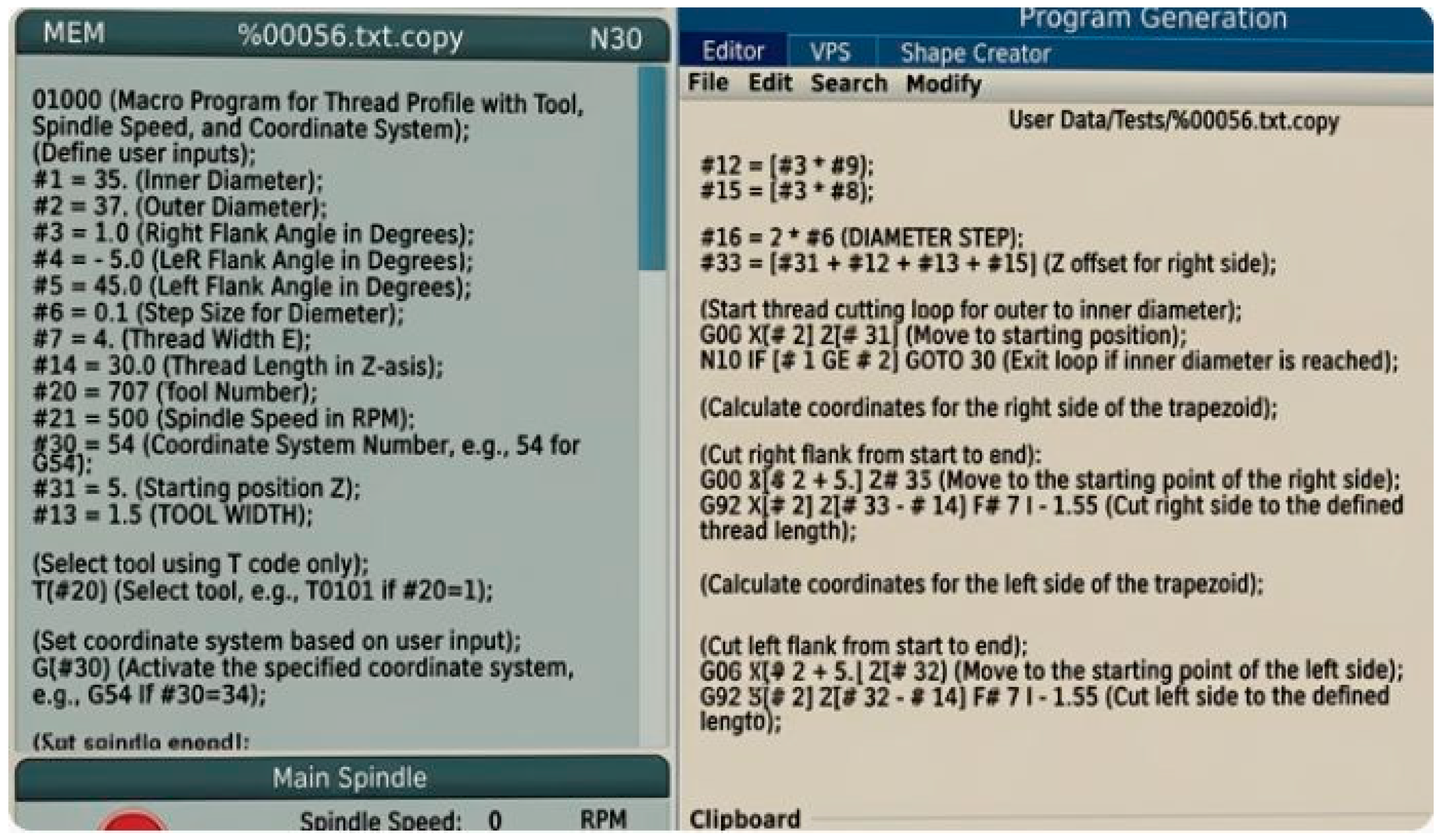
Figure 4 shows a photograph of a passage from the control program for thread cutting, captured from the machine’s control unit.
Figure 4.
Passage from the control program.
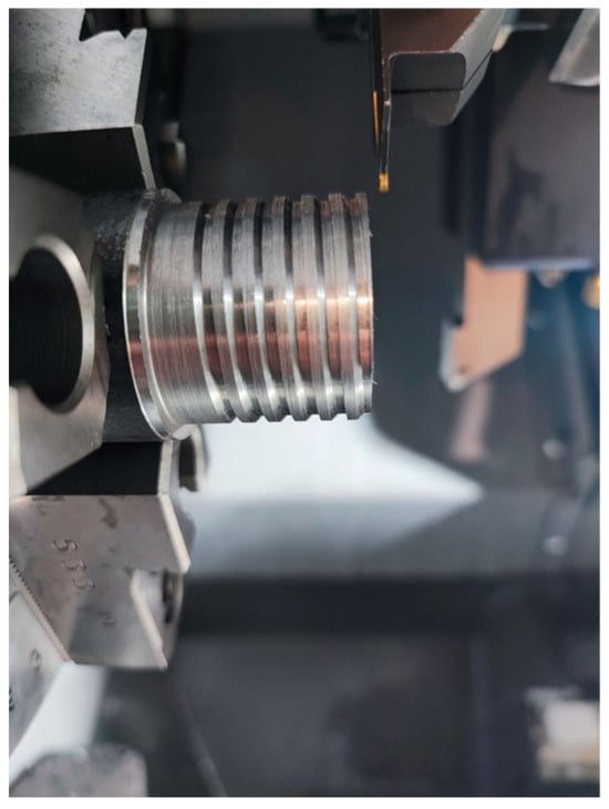
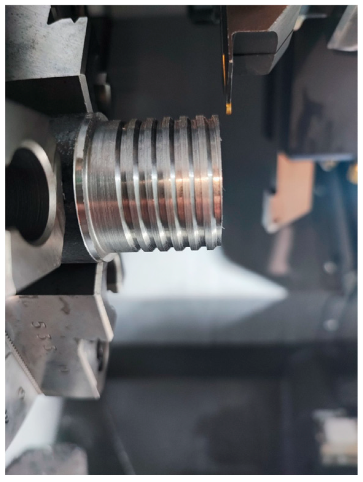
Figure 5 shows a photograph of the machined thread on a test specimen.
Figure 5.
The machined thread.
4. Discussion
The discussed methodology offers a practically applicable approach for machining non-standard trapezoidal thread profiles using a standard grooving insert and parametric programming on a CNC lathe [16]. The developed macro program enables the generation of an asymmetric thread profile through a sequence of synchronized helical motions, realized by the G92 threading cycle.
A significant advantage of the proposed method is the ability to machine various thread profiles without the need for manufacturing a special profile tool. With conventional methods, the tool geometry must correspond to the final thread profile, which requires manufacturing a special tool and leads to increased production costs.
Another important aspect of the developed methodology is the parametric structure of the macro program. The thread profile geometry is determined by a set of input parameters, including external diameter, internal diameter, profile height, thread pitch, and flank inclination angles. These parameters are set by the operator before starting the program and are used to calculate the coordinates of the entry points for each successive pass. In this way, the same program structure can be used to generate different thread profile geometries by changing only the input parameters.
The profile generation is accomplished through a series of successive passes, where the current machining diameter is gradually reduced by a predetermined value. The final thread profile is obtained as a discrete approximation of the theoretical trapezoidal profile geometry, with the accuracy of the resulting profile form depending mainly on the selected radial step between individual passes. Smaller values of this step lead to a more accurate approximation of the theoretical profile but increase the number of required passes and consequently the machining time.
The results obtained from the simulation and experimental machining of a test specimen confirm the applicability of the proposed method. The observed geometry of the resulting thread profile corresponds to the designed asymmetric form, indicating that the analytical description of the profile and the trajectory generation strategy employed enable the realization of non-standard thread profiles using standard cutting tools. However, the accuracy of thread profile machining is precisely a topic with significant research potential. As a continuation of the subject matter of this article, we plan to investigate thread profile accuracy and surface roughness using a microscope profiler.
Another interesting aspect of the applicability of the presented method relates to confirming the physico-mechanical characteristics of an assembly manufactured using this method. It will be interesting to investigate whether the surface machined by this method will exhibit reduced strength properties due to the greater number of stress concentrators resulting from multiple machining passes, as stress concentration and crack growth mechanisms significantly affect structural integrity and fatigue behavior [17,18,19,20].
Author Contributions
Conceptualization, K.C. and P.K.; methodology, K.C., S.S. and P.K.; software S.S. and V.B.; validation, K.C., A.I. and V.B.; formal analysis, K.C. and P.K.; investigation, K.C. and V.B.; resources, S.S. and V.B.; data curation, A.I. and P.K.; writing—original draft preparation, K.C. and V.B.; writing—review and editing, A.I. and P.K.; visualization, A.I. and P.K.; supervision, K.C. and V.B.; project administration, K.C., S.S. and V.B.; funding acquisition, S.S. and P.K. All authors have read and agreed to the published version of the manuscript.
Funding
This research was funded by the European Regional Development Fund within the OP “Research, Innovation and Digitalization Programme for Intelligent Transformation 2021–2027”, Project № BG16RFPR002-1.014-0005 Center of competence “Smart Mechatronics, Eco- and Energy Saving Systems and Technologies”.
Institutional Review Board Statement
Not applicable.
Informed Consent Statement
Not applicable.
Data Availability Statement
Data will be available on request.
Conflicts of Interest
The authors declare no conflicts of interest.
References
- Grabon, W.; Osetek, M.; Mathia, T.G. Friction of threaded fasteners. Tribol. Int. 2018, 118, 408–420. [Google Scholar] [CrossRef] [Scilit]
- Nisbett, J.K. Shigley’s Mechanical Engineering Design; McGraw Hill LLC: Sydney, Austrialia, 2024. [Google Scholar]
- Zheng, M.; Liu, Z.; Li, Y.; Cheng, Y. Experimental Study on Influence Factors of Clamping Force Attenuation of Threaded Fastener. In Advances in Mechanical Design; Tan, J., Ed.; Springer: Singapore, 2022; pp. 839–856. [Google Scholar] [CrossRef] [Scilit]
- Oberg, E.; Jones, E.D.; Horton, H.L.; Ryffel, H.H. Machinery’s Handbook: A Reference Book for the Mechanical Engineer, Designer, Manufacturing Engineer, Draftsman, Toolmaker, and Machinist, 29th ed.; Industrial Press: New York, NY, USA, 2012. [Google Scholar]
- Pohanish, P.R. (Ed.) Machinery’s Handbook Pocket Companion: A Reference Book for the Mechanical Engineer, Designer, Manufacturing Engineer, Draftsman, Toolmaker, and Machinist; Industrial Press: New York, NY, USA, 2000. [Google Scholar]
- Zhong, Q.; Zhai, Z.; Wu, Z.; Xu, C. Thread design optimization of a dental implant using explicit dynamics finite element analysis. Sci. Rep. 2025, 15, 11502. [Google Scholar] [CrossRef] [Scilit] [PubMed]
- Zhou, Y.; Yan, Z.; Zhou, P.; Zheng, Y. Multifactor exploration and multi-objective optimization of trapezoidal threads. Sci. Rep. 2025, 15, 12020. [Google Scholar] [CrossRef] [Scilit] [PubMed]
- Shchurov, I.A.; Nemitova, E.V.; Shchurova, A.; Ardashev, D. Metric Buttress Thread Milling and Turning on CNC Machines. Int. J. Automot. Mech. Eng. 2018, 15, 5146–5160. [Google Scholar] [CrossRef] [Scilit]
- Feng, X.; Luo, Z.; Li, Y.; Liang, H. Fixation stability comparison of bone screws based on thread design: Buttress thread, triangle thread, and square thread. BMC Musculoskelet. Disord. 2022, 23, 854. [Google Scholar] [CrossRef] [Scilit] [PubMed]
- Onysko, O.; Kopei, V.; Barz, C.; Kusyi, Y.; Baskutis, S.; Bembenek, M.; Dašić, P.; Panchuk, V. Analytical Model of Tapered Thread Made by Turning from Different Machinability Workpieces. Machines 2024, 12, 313. [Google Scholar] [CrossRef] [Scilit]
- Malkov, O.; Lagoysky, I.D. Analysis of the technological and kinematic possibility in shaping buttress thread with the general position cutter. Proc. High. Educ. Inst. Mach. Build. 2023, 1, 21–32. [Google Scholar] [CrossRef] [Scilit]
- Amaluddin, M.N.H.; Jamaludin, R.; Mahdali, A. Analysis of The Influence of CNC Milling Macro Programs and Sub-programs Mazak on The Effectiveness Manufacturing Cover of Pressure Cylinder Using CAM. INTEK J. Penelit. 2024, 11, 1–9. [Google Scholar] [CrossRef] [Scilit]
- Mousavi, M.; Wu, M. ISO and DSO Coordination: A Parametric Programming Approach. In Proceedings of the 2023 IEEE Power & Energy Society General Meeting (PESGM), Orlando, FL, USA, 16–20 July 2023; pp. 1–5. [Google Scholar] [CrossRef] [Scilit]
- Wan, N.; He, Q.; Jiang, Y.; Zhou, H.; Fu, B. Numerical and Experimental Investigation of the Influence of the Machining Parameters on Residual Stress Distribution of Internal Thread Cold Extrusion. CIRP J. Manuf. Sci. Technol. 2023, 40, 142–154. [Google Scholar] [CrossRef] [Scilit]
- Haas Automation. ST-10Y CNC Turning Center with Y-Axis. Haas CNC. Available online: https://www.haascnc.com/machines/lathes/st/models/y-axis/st-10y.html (accessed on 5 January 2026).
- Abdullah, Z.T.; Abdulrazaq, A.; Ghazi, S.S. Sustainability Modeling Approach on Remanufacturing Conventional Lathe into CNC Machine Tool. Curr. J. Appl. Sci. Technol. 2020, 39, 1–30. [Google Scholar] [CrossRef] [Scilit]
- Raychev, R.; Delova, I. Methods for reducing the stress concentration in cylindrical specimens at axial loading. Environ. Technol. Resour. Proc. Int. Sci. Pract. Conf. 2021, 3, 300–303. [Google Scholar] [CrossRef] [Scilit]
- Raychev, R.; Delova, I. Reduction of the stress concentration factor of prismatic specimens through the use of topological optimization. Environ. Technol. Resour. Proc. Int. Sci. Pract. Conf. 2021, 3, 296–299. [Google Scholar] [CrossRef] [Scilit]
- Raychev, R.; Delova, I.; Borisov, T.; Mirchev, Y. Crack Growth Modeling in CT Specimens: The Influence of Heat Treatment and Loading. Eng. Proc. 2025, 100, 61. [Google Scholar] [CrossRef] [Scilit]
- Delova, I.; Borisov, T.; Mirchev, Y.; Raychev, R. Numerical Modeling and Analysis of Fatigue Failure in 42CrMo4 Steel Pivot Bolts at Different Heat Treatments. Eng. Proc. 2025, 100, 52. [Google Scholar] [CrossRef] [Scilit]

Disclaimer/Publisher’s Note: The statements, opinions and data contained in all publications are solely those of the individual author(s) and contributor(s) and not of MDPI and/or the editor(s). MDPI and/or the editor(s) disclaim responsibility for any injury to people or property resulting from any ideas, methods, instructions or products referred to in the content. |
© 2026 by the authors. Licensee MDPI, Basel, Switzerland. This article is an open access article distributed under the terms and conditions of the Creative Commons Attribution (CC BY) license.