Mechanical Characterization of PETG/TPU Multi-Material 3D-Printed Samples and Fabrication of a Test Part †



Abstract
1. Introduction
2. Materials and Methods
3D Printing of Test Samples
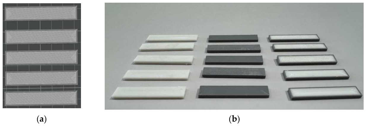
- PETG samples—3D-printed specimens entirely from PETG;
- TPU samples—3D-printed specimens entirely from TPU;
- PETG + 3 TPU samples—3D-printed specimens with a PETG core and three outer walls of TPU;
- PETG + 5 TPU samples—3D-printed specimens with a PETG core and five outer walls of TPU.
- Nozzle temperature: 240 °C;
- Bed temperature: 70 °C;
- Layer height: 0.20 mm;
- Line width: 0.42 mm;
- Elephant foot compensation: 0 mm;
- Slice gap closing radius: 0.04 mm;
- Wall loops: 1;
- Top shell layers: 0;
- Bottom shell layers: 0;
- Infill: 100% (concentric);
- Nozzle diameter: 0.4 mm;
- Infill/wall overlap: 15%;
- Printing speed (for all parameters): 70 mm/s.
3. Results and Discussion
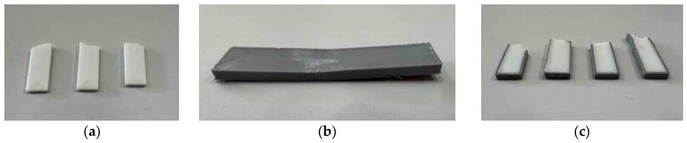
- PETG: The mean deflection angle indicates moderate plastic deformation, demonstrating good impact resistance without failure through brittle fracture. The energy parameters (E/W and E/A) confirm a uniform stress distribution across the cross-section. PETG specimens after fracture are shown in Figure 5a;
- TPU: The TPU specimens do not fracture during testing—only deformation is observed. A deformed TPU sample is shown in Figure 5b;
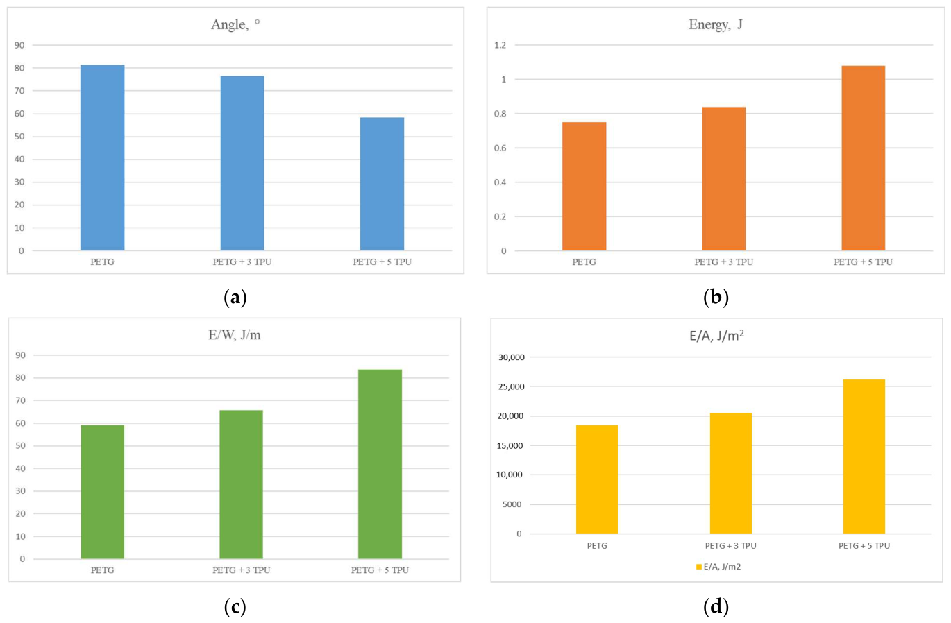
- PETG with three outer TPU walls: In this configuration, an improvement in impact strength is observed compared to the specimen made of pure PETG. The difference in the mean absorbed energy values is about 12% in favor of the PETG + 3 TPU specimens.
- PETG with five outer TPU walls: In this configuration, a significant improvement in the impact strength of the specimens is observed compared to the two produced from pure PETG and those produced from PETG with three outer TPU walls. The mean absorbed energy value for PETG + 5 TPU is about 44% higher than that of the pure PETG specimens and slightly over 28% higher than that of PETG + 3 TPU. Figure 5c shows fractured specimens of the PETG + 5 TPU type.
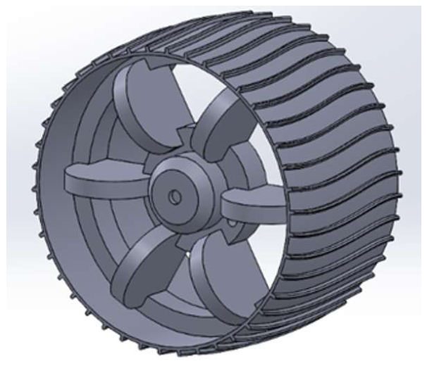
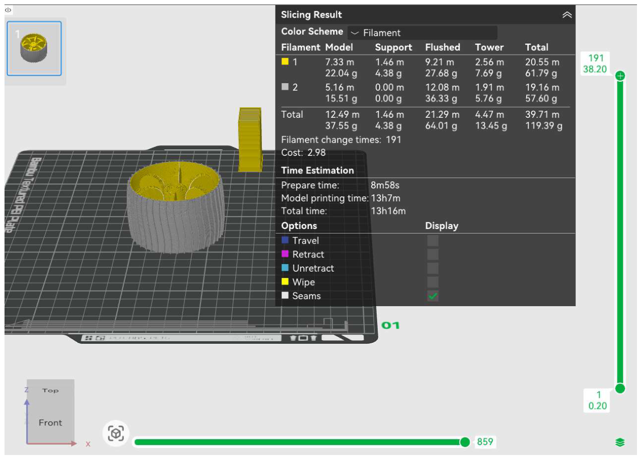
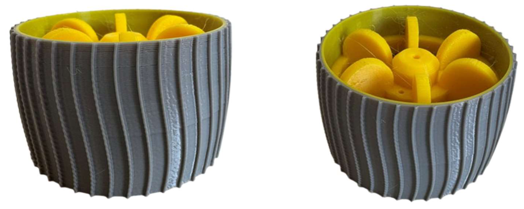
- The inner part (hub and spokes) is printed in Sunlu PETG (yellow) to provide structural strength and stability;
- The outer part (tire) is printed in TPU for AMS (gray), providing elasticity and impact strength.
4. Conclusions
Author Contributions
Funding
Institutional Review Board Statement
Informed Consent Statement
Data Availability Statement
Conflicts of Interest
Abbreviations
| FDM | Fused Deposition Modeling |
| FFF | Fused Filament Fabrication |
| PETG | Polyethylene Terephthalate Glycol |
| TPU | Thermoplastic Polyurethane |
References
- Wolf, M.; Drummer, D. Separation of Multi-Material Polymer Combinations Produced by Joining Using Pin-like Structures. J. Manuf. Mater. Process. 2022, 6, 13. [Google Scholar] [CrossRef]
- Silva, L.R.R.; Marques, E.A.S.; da Silva, L.F.M. Polymer Joining Techniques—State-of-the-Art Review. Weld. World 2021, 65, 2023–2045. [Google Scholar] [CrossRef]
- Todorov, T.T.; Todorov, G.; Sofronov, Y. Optimization of Injection Molding Parameters for Large-Scale Complex Plastic Parts. In Proceedings of the 60th International Scientific Conference on Information, Communication and Energy Systems and Technologies (ICEST 2025), Ohrid, North Macedonia, 26–28 June 2025; pp. 1–4. [Google Scholar] [CrossRef]
- Petrov, K.; Tongov, E. Mechanical System for Wire Arc Additive Manufacturing. In Proceedings of the International Scientific and Practical Conference “Environment. Technologies. Resources.”, Rezekne, Latvia, 15–16 June 2023; Volume 1, pp. 171–174. [Google Scholar] [CrossRef]
- Mao, J.; Hsu, L.; Altheeb, M.; Grigoriadis, K. Fused Space in Architecture via Multi-Material 3D Printing Using Recycled Plastic: Design, Fabrication, and Application. Buildings 2025, 15, 2588. [Google Scholar] [CrossRef]
- Komarski, D. Goniometric Module with Cross-Shaped Elastic Guides Study. In Proceedings of the 2024 XXXIV International Scientific Symposium on Metrology and Metrology Assurance (MMA), Sozopol, Bulgaria, 7–11 September 2024; pp. 1–4. [Google Scholar] [CrossRef]
- Meng, Z.; Yuan, W.; Ren, Y. Multi-Material Conceptual Design of Aircraft Engine Pylon Based on Floating Projection. AIAA J. 2025, 63, 3514–3520. [Google Scholar] [CrossRef]
- Todorov, T.; Bineva, K.; Romanov, B. Validation of Design and Ergonomics of a Protective Mask by Creating a Silicone Replication in a 3D Printed Mold Tool. Mech. Mach. Sci. 2025, 174, 335–344. [Google Scholar] [CrossRef]
- Raj, R.; Song, Q.-C.; Juang, J.-Y. Multi-Material Additive Manufacturing of Soft Robotic Systems: A Comprehensive Review. Adv. Robot. Res. 2025, 2, e202500064. [Google Scholar] [CrossRef]
- Todorov, G.; Sofronov, Y.; Bineva, K. Comparison Analysis Between Different Technologies for Manufacturing Patient-Specific Implants. In Advances in Manufacturing, Lecture Notes in Mechanical Engineering; Springer: Cham, Switzerland, 2022; Chapter 27. [Google Scholar] [CrossRef]
- Farrugia, J.; Vella, P.; Rochman, A. Combining 3D Printing and Injection Moulding for the Fabrication of Polymer Micro-Components with Internal Hollow Features. Prog. Addit. Manuf. 2024, 9, 1353–1364. [Google Scholar] [CrossRef]
- Romero-Araya, P.; Pino, V.; Nenen, A.; Cárdenas, V.; Pavicic, F.; Ehrenfeld, P.; Serandour, G.; Lisoni, J.G.; Moreno-Villoslada, I.; Flores, M.E. Combining Materials Obtained by 3D-Printing and Electrospinning from Commercial Polylactide Filament to Produce Biocompatible Composites. Polymers 2021, 13, 3806. [Google Scholar] [CrossRef] [PubMed]
- Halbig, M.C.; Singh, M. Additive Manufacturing of Multi-Material Systems for Aerospace Applications. In Proceedings of the MS&T19—Materials Science & Technology 2019, Portland, OR, USA, 29 September–3 October 2019; NASA Report No. GRC-E-DAA-TN73588. Available online: https://ntrs.nasa.gov/citations/20190032205 (accessed on 4 March 2026).
- Zhou, Q.; Sang, Z.; Gardea, F.; Lee, S.; Pharr, M.; Sukhishvili, S.A. A Tailorable Family of Elastomeric-to-Rigid, 3D Printable, Interbonding Polymer Networks. Adv. Funct. Mater. 2020, 30, 2002374. [Google Scholar] [CrossRef]
- Xia, Y.; Sang, M.H.; Wang, X.; He, N.; Wang, H.T.; Li, Y.J. Overcoming the Trade-Off between Toughness and Stiffness of Fully Polymer-Based Alloys by Elastomeric Salami Particles through Reactive Blending. Chin. J. Polym. Sci. 2026, 44, 675–687. [Google Scholar] [CrossRef]
- Nakagawa, S. Mechanical Properties of Model Network Elastomers: Impacts of Network Geometry and Chemistry. Polym. J. 2026, 58, 629–638. [Google Scholar] [CrossRef]
- Frenkel, D.; Ginsbury, E.; Sharabi, M. The Mechanics of Bioinspired Stiff-to-Compliant Multi-Material 3D-Printed Interfaces. Biomimetics 2022, 7, 170. [Google Scholar] [CrossRef] [PubMed]
- de Sousa Filho, V.A.; de Alencar Lira, M.C.; Pereira Bonfim, R.L.; Braga da Cunha, R.; Nóbrega Cavalcanti, S.; Quirino Brito, L.B.; Agrawal, P.; de Figueiredo Brito, G.; Alves de Mélo, T.J. Reactive and Non-Reactive Compatibilization of Polyethylene Terephthalate Glycol/Thermoplastic Polyurethane (PETG/TPU) Blends for 3D/4D Printing Applications. React. Funct. Polym. 2025, 215, 106393. [Google Scholar] [CrossRef]
- ASTM D256-10(2018); Standard Test Methods for Determining the Izod Pendulum Impact Resistance of Plastics. ASTM International: West Conshohocken, PA, USA, 2018.



| Sample Type | Impact Energy, J | Angle, ° | E (J) | E/W, J/m | E/A, J/m2 |
|---|---|---|---|---|---|
| PETG | |||||
| 1 | 5.50 | 72.23 | 0.91 | 71.68 | 22,399.32 |
| 2 | 5.50 | 77.86 | 0.82 | 64.20 | 20,060.85 |
| 3 | 5.50 | 86.27 | 0.66 | 52.24 | 16,324.42 |
| 4 | 5.50 | 82.94 | 0.73 | 57.06 | 17,830.24 |
| 5 | 5.50 | 87.62 | 0.64 | 50.27 | 15,708.67 |
| TPU | |||||
| 1 | 5.50 | No fracture observed. | |||
| 2 | 5.50 | ||||
| 3 | 5.50 | ||||
| 4 | 5.50 | ||||
| 5 | 5.50 | ||||
| PETG + 3 TPU | |||||
| 1 | 5.50 | 77.50 | 0.88 | 64.69 | 20,215.20 |
| 2 | 5.50 | 75.74 | 0.85 | 67.09 | 20,964.67 |
| 3 | 5.50 | 86.9 | 0.65 | 51.32 | 16,037.33 |
| 4 | 5.50 | 70.75 | 0.93 | 73.53 | 22,976.65 |
| 5 | 5.50 | 72.14 | 0.91 | 71.79 | 22,435.07 |
| PETG + 5 TPU | |||||
| 1 | 5.50 | 64.76 | 1.02 | 80.50 | 25,157.56 |
| 2 | 5.50 | 61.79 | 1.06 | 81.64 | 25,514.10 |
| 3 | 5.50 | 60.85 | 1.07 | 82.52 | 25,788.14 |
| 4 | 5.50 | 42.12 | 1.20 | 93.02 | 29,067.84 |
| 5 | 5.50 | 62.33 | 1.06 | 81.12 | 25,350.33 |
| Sample Type | Impact Energy, J | Angle, ° | E (J) | E/W, J/m | E/A, J/m2 |
|---|---|---|---|---|---|
| PETG | 5.50 | 81.38 | 0.75 | 59.09 | 18,464.70 |
| TPU | 5.50 | No fracture observed. | |||
| PETG + 3 TPU | 5.50 | 76.61 | 0.84 | 65.68 | 20,525.78 |
| PETG + 5 TPU | 5.50 | 58.37 | 1.08 | 83.76 | 26,175.59 |
| Sample Type | Top Surface | Side Wall | Mean Value |
|---|---|---|---|
| PETG | 81.7 | ||
| 1 | 80 | 81 | |
| 2 | 78 | 85 | |
| 3 | 86 | 83 | |
| 4 | 84 | 81 | |
| 5 | 81 | 78 | |
| TPU | |||
| 1 | 69 | 67 | 67.6 |
| 2 | 68 | 68 | |
| 3 | 66 | 67 | |
| 4 | 67 | 70 | |
| 5 | 68 | 66 | |
Disclaimer/Publisher’s Note: The statements, opinions and data contained in all publications are solely those of the individual author(s) and contributor(s) and not of MDPI and/or the editor(s). MDPI and/or the editor(s) disclaim responsibility for any injury to people or property resulting from any ideas, methods, instructions or products referred to in the content. |
© 2026 by the authors. Licensee MDPI, Basel, Switzerland. This article is an open access article distributed under the terms and conditions of the Creative Commons Attribution (CC BY) license.
Share and Cite
Zagorski, M.; Miltchev, R.; Gavrilov, T.; Nikolova, M. Mechanical Characterization of PETG/TPU Multi-Material 3D-Printed Samples and Fabrication of a Test Part. Eng. Proc. 2026, 150, 71. https://doi.org/10.3390/engproc2026150071
Zagorski M, Miltchev R, Gavrilov T, Nikolova M. Mechanical Characterization of PETG/TPU Multi-Material 3D-Printed Samples and Fabrication of a Test Part. Engineering Proceedings. 2026; 150(1):71. https://doi.org/10.3390/engproc2026150071
Chicago/Turabian StyleZagorski, Mihail, Radoslav Miltchev, Todor Gavrilov, and Martina Nikolova. 2026. "Mechanical Characterization of PETG/TPU Multi-Material 3D-Printed Samples and Fabrication of a Test Part" Engineering Proceedings 150, no. 1: 71. https://doi.org/10.3390/engproc2026150071
APA StyleZagorski, M., Miltchev, R., Gavrilov, T., & Nikolova, M. (2026). Mechanical Characterization of PETG/TPU Multi-Material 3D-Printed Samples and Fabrication of a Test Part. Engineering Proceedings, 150(1), 71. https://doi.org/10.3390/engproc2026150071