


Abstract
This study represents the evaluation of the aeroelastic flutter stability characteristics of a helicopter rotor, expressed as correlations between the flutter frequency ratio and the relative center of gravity coordinate, considering the varying distance from the ground surface and the location of the aerodynamic center for a fixed flapping frequency. For every constant aerodynamic center’s coordinate, a decrease in the relative distance from the ground surface produces a reduction in the flutter stability zone for the given helicopter rotor. Conversely, moving the center of gravity coordinates in the backward direction from to leads to a rise in the flutter stability zone and then improves the stability characteristics. A nonlinear representation of the lift force coefficient variations with the angle of attack, when the reduced frequency changes from to , is conducted with the incorporation of Theodorsen’s function. Eventually, an increase in the reduced frequency magnitude leads to a rise in the produced nonlinearities in the lift force coefficients when the angle of attack changes.
1. Introduction
The flutter phenomenon is an aeroelastic instability that occurs on airplane wings and on helicopter rotors and involves both bending and torsion motions, which, specifically for the case of a helicopter rotor, include pitch and flap variations in the blade. In detail, the inclusion of the center of gravity and aerodynamic center’s relative coordinates is an important step required for defining the stability zone with respect to the flutter characteristics [1]. The flutter on a helicopter rotor generally happens when the frequency of the aerodynamic oscillations coincides with the helicopter blade’s frequency and then produces an uncontrolled vibration, caused due to interactions between the existing aerodynamic forces, the inertial forces and the structural properties of the system (elastic forces). The blade’s complex motion, when the flutter happens, can include a chordwise (lag) component, a twisting component (torsion) and a bending component and may possibly lead to loss of control, damage or destruction of the helicopter blades. The existence of the flutter phenomenon can be controlled considering several structural and operational properties of the rotor blades. In the design phase, the most common solution includes consideration of the blade’s shape and material to achieve a proper stiffness. The operational parameters that may contribute to the existence of the flutter phenomenon include the properties of the surrounding air and the rotational frequency of the helicopter rotor. In detail, the more flexible the rotor’s blades are and the higher the rotational frequency is, the higher the risk for flutter occurrence will be. To predict the flutter phenomenon on a helicopter rotor, the unsteady aerodynamics must be modeled [2].
Several researchers united their efforts to investigate the flutter stability of a helicopter rotor blade and to deliver solutions. Kreshock et al. conducted a whirl flutter stability analysis of a tiltrotor in a transonic dynamics tunnel [3]. Experimental testing for the model XV-5 with two types of blades-a fiberglass and a carbon fiber blade-has been conducted and further compared to the numerical predictions, derived using CAMRAD II and RCAS [3]. The delivered results illustrate that the fiberglass blades show a stabilizing effect at higher speeds due to the dynamic coupling between the rotor and the airframe [3]. The authors observed two types of instabilities-a tiltrotor whirl flutter and a proprotor whirl flutter; the first one is produced by the gimbal and the dynamics of the airframe, and the second one includes a coupling with the blade flexibility [3]. Additionally, McKechnie and Barakos represented two fluid-structure interaction methods [4]. The structural effect is represented by means of a 3D finite element method, and a comparison between the time-marching and quasi-static computations is delivered [4]. As a result, the time-marching calculations indicate that the deformations and the vibrations are happening due to stall, and the verifications have been conducted by comparing the blade response and the flow off the blade [4]. Sutherland et al. conducted and represented a flutter stability wind tunnel test of the Maryland Tiltrotor Rig [5]. The authors described the swept-tip blades, which are the same as the straight blades up to 80% of the radius, and then up to the tip section, a 20° sweep angle is included to reduce the whirl flutter [5]. Moreover, the rotor frequencies, stress and strain were evaluated by means of the 3D finite element analysis and then validated through the vacuum chamber experiments [5]. As a result, the whirl tests are conducted for two blade geometries and for four configurations, varying the wind speed up to 100 knots and clearly illustrating higher wing chord damping in free-wheel flight even at lower flight speeds [5]. Additionally, Delgado and Datta performed high-speed whirl flutter testing up to 200 kts of a swept-tip proprotor [6]. Stability roots for a wing-pylon beam, chord and torsion motions were estimated [6]. The represented results indicate that the swept-tip blades provided a higher damping of the wing chord, and no effect on the beam mode was observed [6]. Arnold provided an assessment of the flutter stability characteristics of a rotor blade in hover by coupling the multibody model and the aerodynamic model [7]. In detail, the mathematical model is enhanced to axial flow to include the unsteady effects in the rotor’s inflow and in the wake periodicity [7]. The derived results are represented in terms of frequency and damping for three cases. Consequently, the derived results for the articulated rotor blade illustrate a bending-torsion coupling [7]. The lowest flutter occurrence is observed for the airfoil section, showing the same results as if the rotor inflow and the wake were included at a 5% higher rotational speed [7]. Additionally, the torsion damping shows an increase due to the influence of the rotor inflow [7]. Moreover, the frequency and the damping are not affected by the inclusion of the wake [7]. Krüger investigated the whirl flutter phenomenon on a tiltrotor in a wind tunnel [8]. In detail, the variations in the parameters and the non-linearities in the estimation of the stability boundaries were evaluated [8]. The experimental investigations were performed in the frequency and in the time domain, and a significant difference has been observed for the linear and for the non-linear models [8]. The whirl flutter of a three-bladed tiltrotor with the application of the viscous vortex particle method, uniform inflow and dynamic inflow was additionally researched by Cocco and Savino [9]. As a result, a good correlation between the vortex particle method and the dynamic inflow was observed; however, the uniform inflow indicates different trends [9]. Additionally, the inclusion of the effect of the wing aerodynamics led to a deviation in the wing bending mode flutter results derived by the application of the vortex particle method, reducing the damping [9]. A study of the flutter stability of a propeller and the effect of the aerodynamic torque has been investigated by Böhnisch et al. [10]. The inclusion of the torque in the equations modifies the real parts of the forward and the backward modes and then improves the stability [10]. Eventually, the results are represented with an analytical method further validated with a coupled multibody simulation and a vortex particle method [10]. Additionally, the control variables are changed to improve the whirl flutter stability [10]. Despite the successes of this control strategy, the propeller’s efficiency is reduced [10]. The whirl flutter instabilities for a proprotor have been investigated by Kunz [11]. In detail, the factors that contribute to this phenomenon are reviewed, and their effect on stability is considered for propellers, proprotors and helicopter rotors [11]. The aeroelastic stability of a helicopter rotor with a trailing edge flap is examined by Shen and Chopra [12]. The conducted stability calculations show that both the flap aerodynamic over-balancing and flap mass-unbalancing will have a destabilizing effect on the blade and flap system [12]. Moreover, the represented research showed that a decline in the blade’s torsion stiffness or actuator stiffness will lead to a blade torsion-flap phenomenon [12]. Additionally, the whirl flutter stability of a two-bladed proprotor in high-speed axial flight has been researched with several parametric studies by Singh and Chopra [13]. As a result, the wing beam bending mode is considered stable for the whole range of examined parameters, and the wing torsion mode shows a new type of instability, which resembles the wing torsion instability but happens at frequency 1/rev [13]. The interaction between the wing chordwise and bending modes is found to be considerably higher for the two-bladed rotors [13]. Hathaway and Gandhi examined different controller designs, including gain-scheduled full-state feedback optimal control, constant-gain full-state controllers and single-state feedback systems [14]. The conducted study estimated the feedback of the wing’s vertical and chordwise bending modes [14]. Moreover, the analysis of rotor design to improve the flutter stability margins was conducted by Acree et al. [15]. A composite thinner wing was implemented for the high-speed operating conditions, reducing the drag and the flutter stability as well [15]. Then modification of the rotor’s blade design, which generally aims to place the aerodynamic center relatively backward, was made to increase the stability speed margin [15]. The researchers concluded that the swept-tip blades at 80% of their radius significantly increase the stability boundary, but when they are combined with a proper stiffness magnitude, the whirl flutter stability does not exist [15]. Additionally, the tiltrotor whirl flutter stability can be improved with the use of wing flaperons [16]. Tang and Dowell represented the limit cycle oscillation and the behavior of both the flutter and the forced response for three combinations of linear and nonlinear structure, with linear and nonlinear aerodynamic models [16]. As a result, the derived comparisons provide a novel understanding for the nonlinear aeroelastic phenomena [16]. Moreover, Mueller et al. represented a study on the use of active control to improve flutter stability [17]. A controller with two types of algorithms, Linear Quadratic Gaussian Control and Generalized Predictive Control, has been researched and applied to the chosen aeroelastic model [17]. As a result, the measurements of the wing deflections have been used for the swashplate input [17]. The applied controller improves the stability and is suitable for industrial applications [17].
Given the conducted literature review, this study aims to investigate analytically the flutter stability boundaries of a helicopter rotor given the variation in several parameters. The aerodynamic characteristics of the examined helicopter rotor have been previously derived experimentally [18] and further validated numerically [19,20]. Firstly, the flutter stability boundaries will be evaluated when the helicopter rotor hovers in ground effect conditions when the operational distance varies from to and . The estimated boundaries will be analyzed as correlations between the flutter frequency ratio and the relative center of gravity position . Additionally, the flutter frequency ratio will be estimated again as a function of the relative center of gravity coordinate when the aeroelastic damping ratio (aerodynamic center relative coordinate) varies from to and for the conditions without the influence of the ground effect. The application of Theodorsen’s complex function will be discussed and will be done for the estimation of the lift force coefficient variations over the angle of attack when the reduced frequency changes from to , , , and . As a result of this study, the variations in the flutter stability boundaries when the operational parameters change will be estimated and analyzed. Further, the zone without the flutter phenomenon for every operational case will be described.
2. Estimation of Flutter Stability for a Helicopter Rotor
2.1. Flutter Instability of a Helicopter Rotor
Generally, the flutter phenomenon occurs when a pair of complex conjugate roots crosses the imaginary axis into the right half-plane [1]. Then, the stability boundary can be defined considering the probability of one existing root to cross the imaginary axis [1].
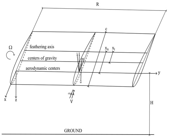
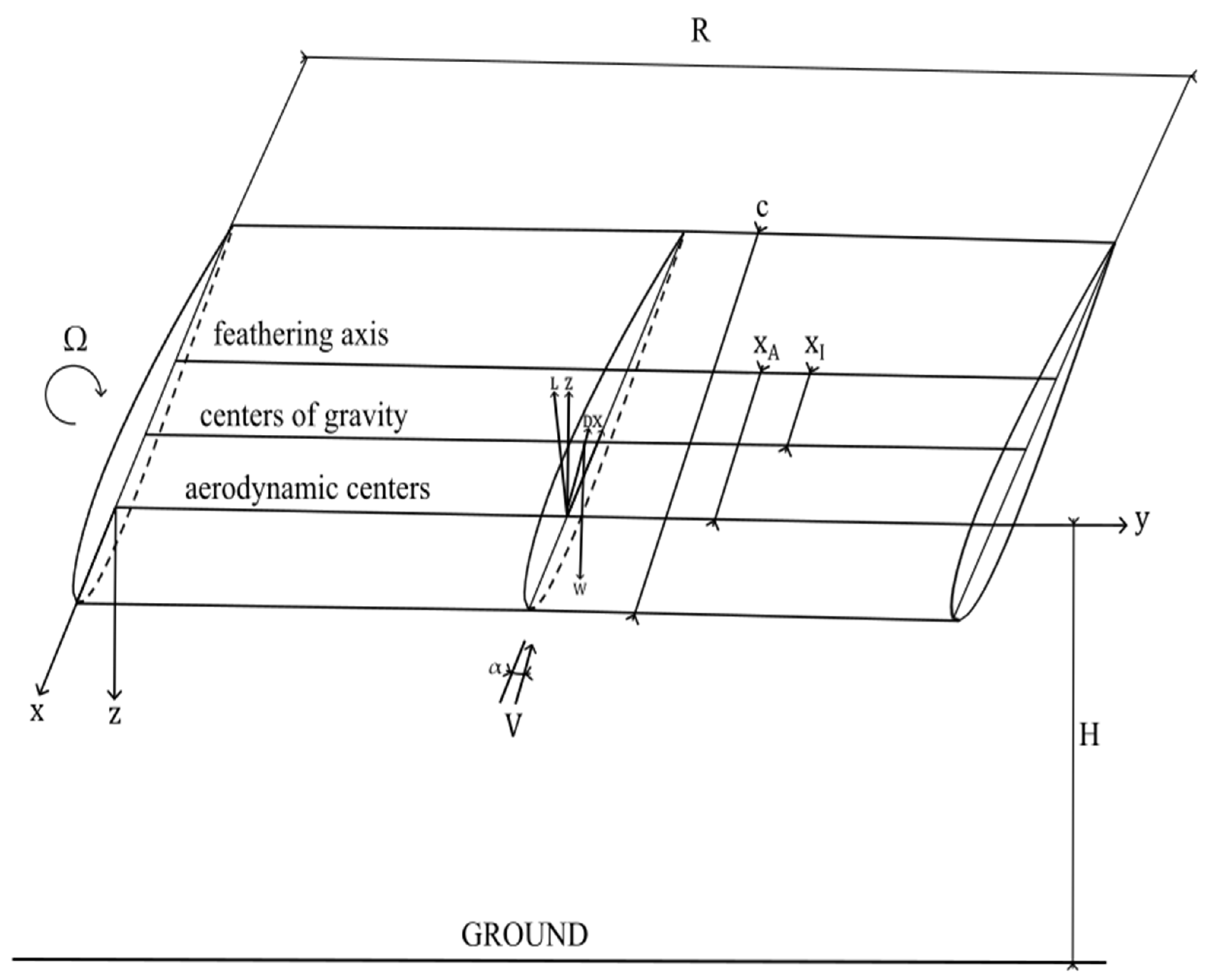
In Figure 1 a general representation of the aeroelastic model of the blade, which is used in the analysis, is provided.
Figure 1.
Aeroelastic model for a rotating blade.
The characteristic equations, which define the flutter stability with their real and imaginary parts, can be represented in the following form, according to Equations (1) and (2) [1]:
where and are the flutter frequency and the pitch natural frequency, respectively, is the blade’s flapping frequency, and is the pitch-flap coupling.
The inertial coefficients , and and the blade’s normal moment of inertia in the flapping direction included in the flutter stability real and imaginary part equations, can be evaluated in accordance with Equations (3)–(6), respectively [1]:
where is the rotor’s radius, is the blade’s mass, is the length of each blade element, is the distance between the blade’s feathering axis and the center of gravity, and is the section moment of inertia about the feathering axis.
The aerodynamic coefficients, included in the flutter stability real and imaginary part equations, can be estimated in accordance with Equations (7)–(14) as follows [1]:
where is the relative distance between the feathering axis and the aerodynamic center, is the lift deficiency function, is the blade’s chord, is the effective reduced frequency, and and are coefficients.
The effective reduced frequency can be evaluated considering the frequency of the oscillation , the chord length and the radius of gyration about the elastic axis with respect to Equation (15) [1]:
Moreover, the aerodynamic coefficients and generally represent a relation between the aerodynamic and the inertial coefficients with respect to Equations (16) and (17) as follows [1]:
In the represented Equations (1) and (2), the magnitudes of and are small, and for the least magnitude of , the equations can be written in the following form (18) and (19) [1]:
Then, the imaginary part can be solved for the flutter frequency according to Equations (20) and (21) [1]:
As a result, the flutter stability criterion can be derived by substituting the flutter frequency in the represented real part as follows (22) [1]:
where the coefficients and can be written in the following form, according to Equations (23)–(26):
As a result, the criterion for flutter stability can be represented, with respect to Equation (27) [1]:
2.2. Theodore Theodorsen’s Function for Flutter Stability of a Helicopter Rotor
The Theodorsen function provides a relation between the angle of attack and the aerodynamic responses in terms of lift distribution and pitching moment [2]. The solution of this function is in complex form and can be expressed in terms of Equation (28):
where are the Hankel functions and is the reduced frequency.
The reduced frequency can be estimated according to Equation (29) [2]:
where is the freestream velocity.
The Hankel function can be defined as , where and are the Bessel functions.
Considering the Bessel functions, the Theodorsen function could be represented with its real and imaginary parts in the form of (30) and (31) [2]:
Taking into account the complex properties, the amplitude and the phase can be calculated according to Equations (32) and (33) [2]:
If we consider an oscillatory variation in the angle of attack , the variations in the lift force coefficient can be estimated in the form illustrated in Equation (34) [2]:
As a result, for the unsteady regime, the variation in the lift force coefficient can be evaluated according to Equation (35) [2]:
Then, the real and imaginary parts of the Theodorsen function could be calculated considering the expressions (36) and (37) as follows [2]:
Additionally, the amplitude and the phase of the Theodorsen function could be estimated in accordance with Equations (38) and (39) [2]:
The above-represented two analytical models [1,2] will be correlated with the conditions of the performed numerical task, taking into account the geometric, operational, inertial, and aerodynamic parameters, to estimate the flutter stability boundaries and the lift force coefficient variations in the examined helicopter rotor. One of the most significant correlations involves the inclusion of the rotor’s inertial parameters in the models. The proper incorporation of the rotor’s mass and geometric properties is essential for accurately estimating the flutter stability boundaries under varying conditions.
Another important aspect is the integration into the models of the lift force coefficient derivative with respect to the angle of attack , based on the aerodynamic characteristics of the selected airfoil, to ensure accurate estimation of lift force coefficient variations as a function of the angle of attack.
3. Numerical Approaches
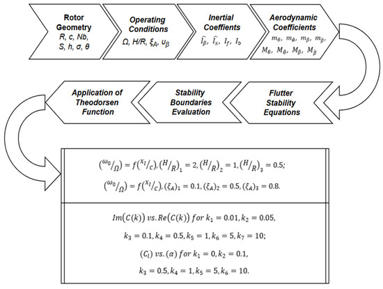
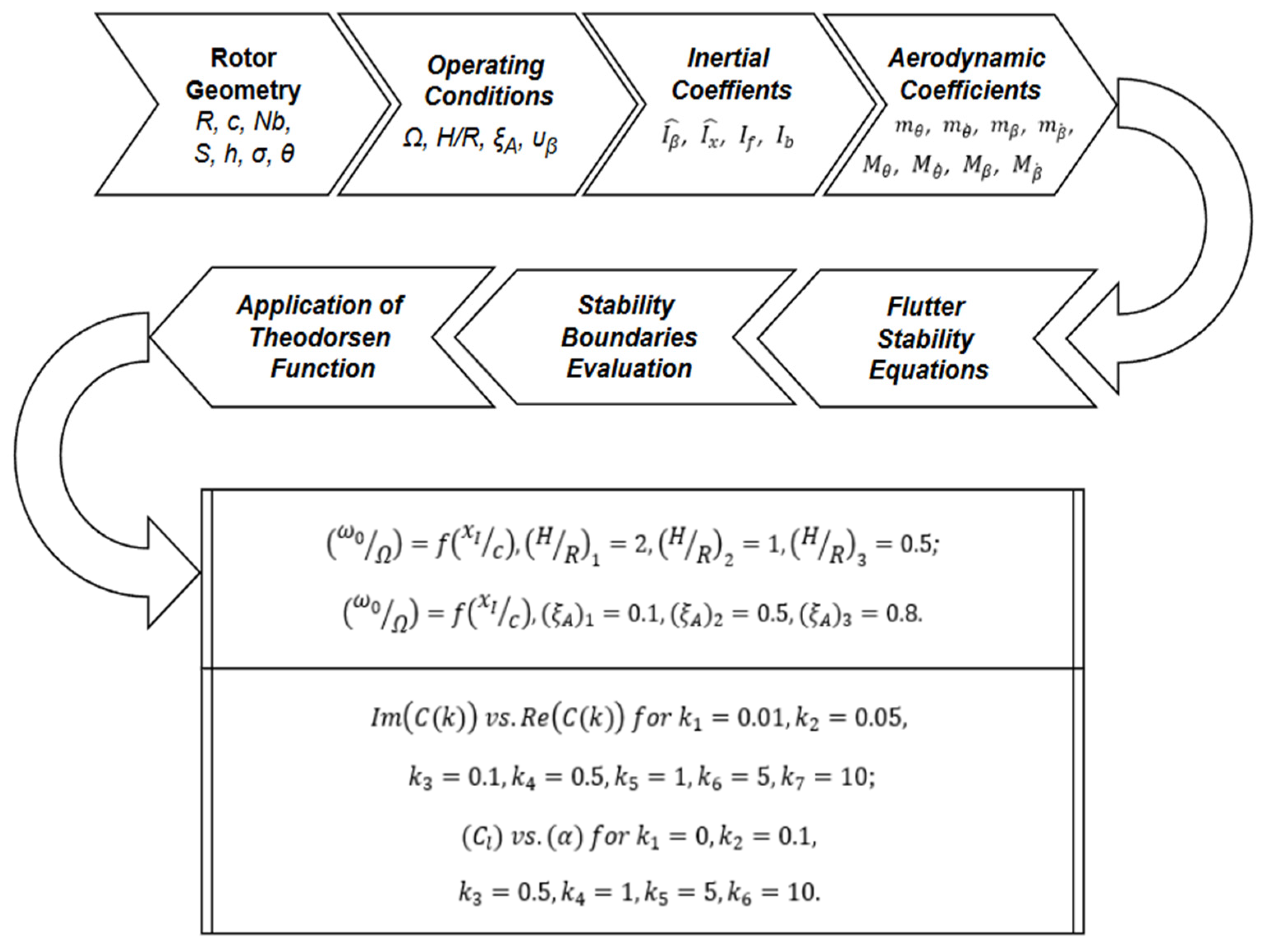
The applied computational methodology in this research task includes two numerical approaches, which follow one after the other, presented in Figure 2. Both numerical approaches require the definition of the rotor’s geometric parameters and the operating conditions: the rotor’s radius , the chord of the blades , the number of blades , the area , the rotor’s height above the center of gravity , the rotor’s solidity , the collective pitch angle , the rotational frequency , the relative distance from the ground surface the aerodynamic center relative coordinate and the flapping frequency are among the most important parameters applied in this task. The examined helicopter rotor was previously represented with its geometric parameters and tested experimentally [18]. Additionally, all the inertial and aerodynamic coefficients, which are described above, are also defined as a prerequisite for solving the task, according to Figure 2.
Figure 2.
Numerical approaches.
For solving the two numerical tasks, a MATLAB code was developed using MATLAB R2022b and MATLAB Online R2026a to include the whole range of the examined geometric, operational, inertial and aerodynamic parameters.
The first numerical approach aims to evaluate the flutter stability boundaries of the examined helicopter rotor, represented as dependencies between the flutter frequency ratio and the center of gravity relative coordinate , when the operational distance from the ground surface to the rotor’s plane of rotation varies from to and . Further, the flutter frequency ratio will be examined again as a function of the relative center of gravity location when the aerodynamic center coordinates vary for a fixed flapping frequency . In detail, the stability boundaries can be estimated by solving Equations (1) and (2) considering the rotor’s geometry and the inertial and aerodynamic coefficients.
The second numerical approach will evaluate the nonlinear variations in lift force coefficients when the angle of attack changes for several reduced frequency magnitudes (k): , , , , , by incorporating Theodorsen’s function in the computations, whose solution is represented in Equation (28). In order for the nonlinear responses to be estimated, Theodorsen’s function imaginary and real parts must be evaluated for several reduced frequencies (k). As a result, the aerodynamic responses, presented as variations in the lift force coefficients with the angle of attack , will be computed and analyzed for the whole set of examined reduced frequencies .
4. Observations
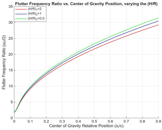
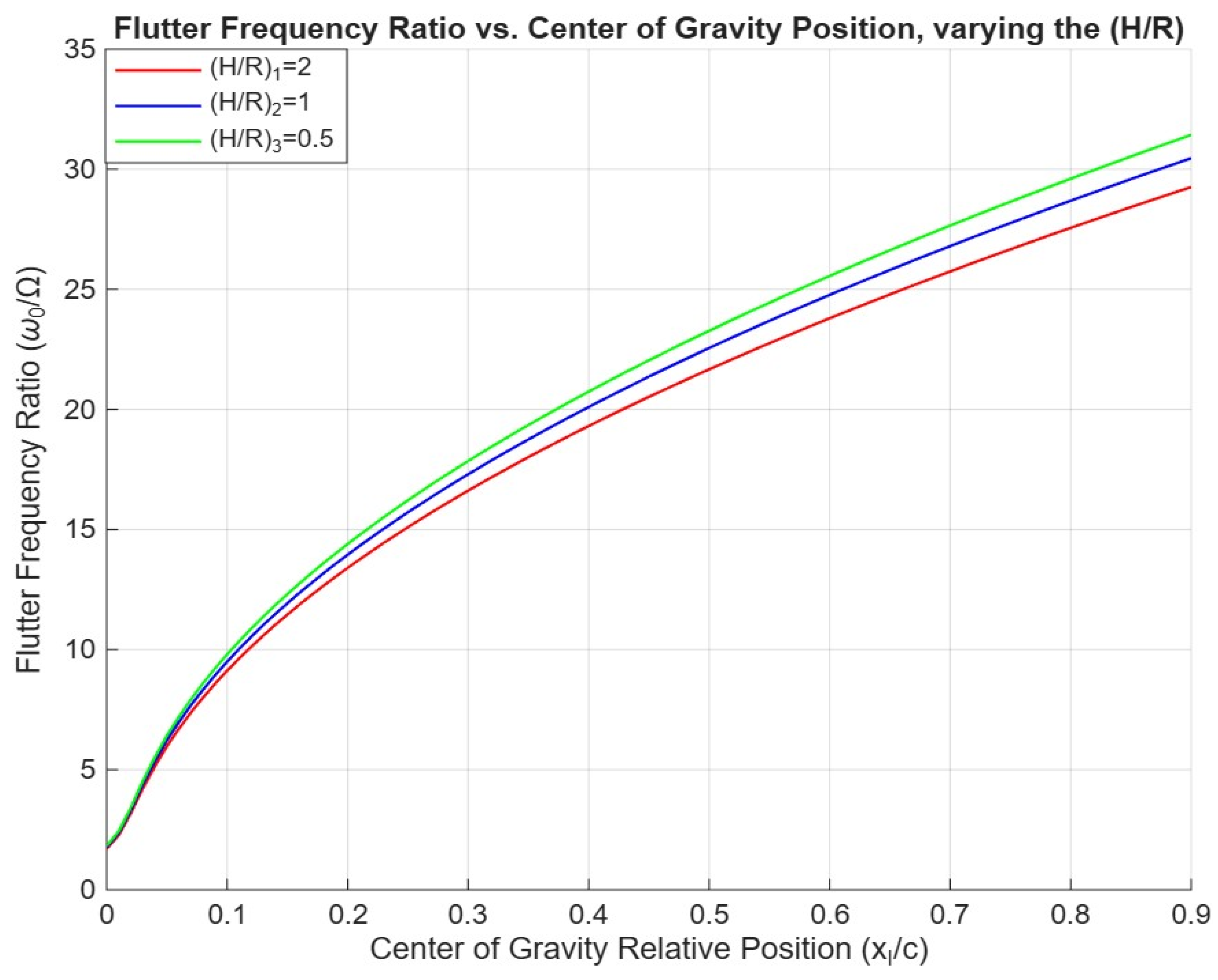
The flutter stability boundaries can be graphically illustrated once Equations (1) and (2) are solved for the whole set of operating conditions. Figure 3 represents the dependencies between the flutter frequency ratio and the relative center of gravity location , varying the relative distance from the ground surface from to and . The illustrated dependencies show that an increase in the system’s stiffness produces a rise in the stability boundaries for all the operational distances from the ground surface.
Figure 3.
Flutter frequency ratio vs. center of gravity relative position for different relative distances from the ground surface .
According to the represented correlations, a decrease in the operational distance from the helicopter’s rotational plane to the ground will reduce the stability area for every given relative center of gravity coordinate . Moreover, the higher the center of gravity relative coordinate is, the higher the increase in the flutter frequency ratio can be observed. In accordance with the represented dependencies, when the relative center of gravity coordinate is , a decline in the relative distance from the helicopter’s rotational plane to the ground surface from to and will produce an additional increase in the system’s stiffness equal to approximately 8.3% and 9.8%, respectively. Moreover, the stiffness increase at is equal to 6.8% and 3.4%, correspondingly. Additionally, considering a fixed aerodynamic center coordinate at , moving the center of gravity relative location in the direction of the leading edge will additionally increase the rotor’s flutter stability level. In other words, flutter stability will increase when the coefficient decreases. Moreover, the stability balance can be improved by including additional mass in the zone of the leading edge.
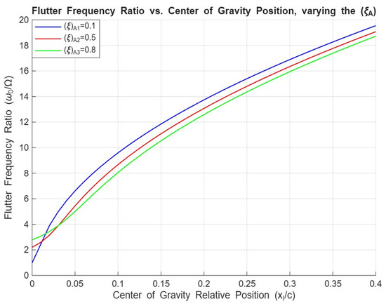
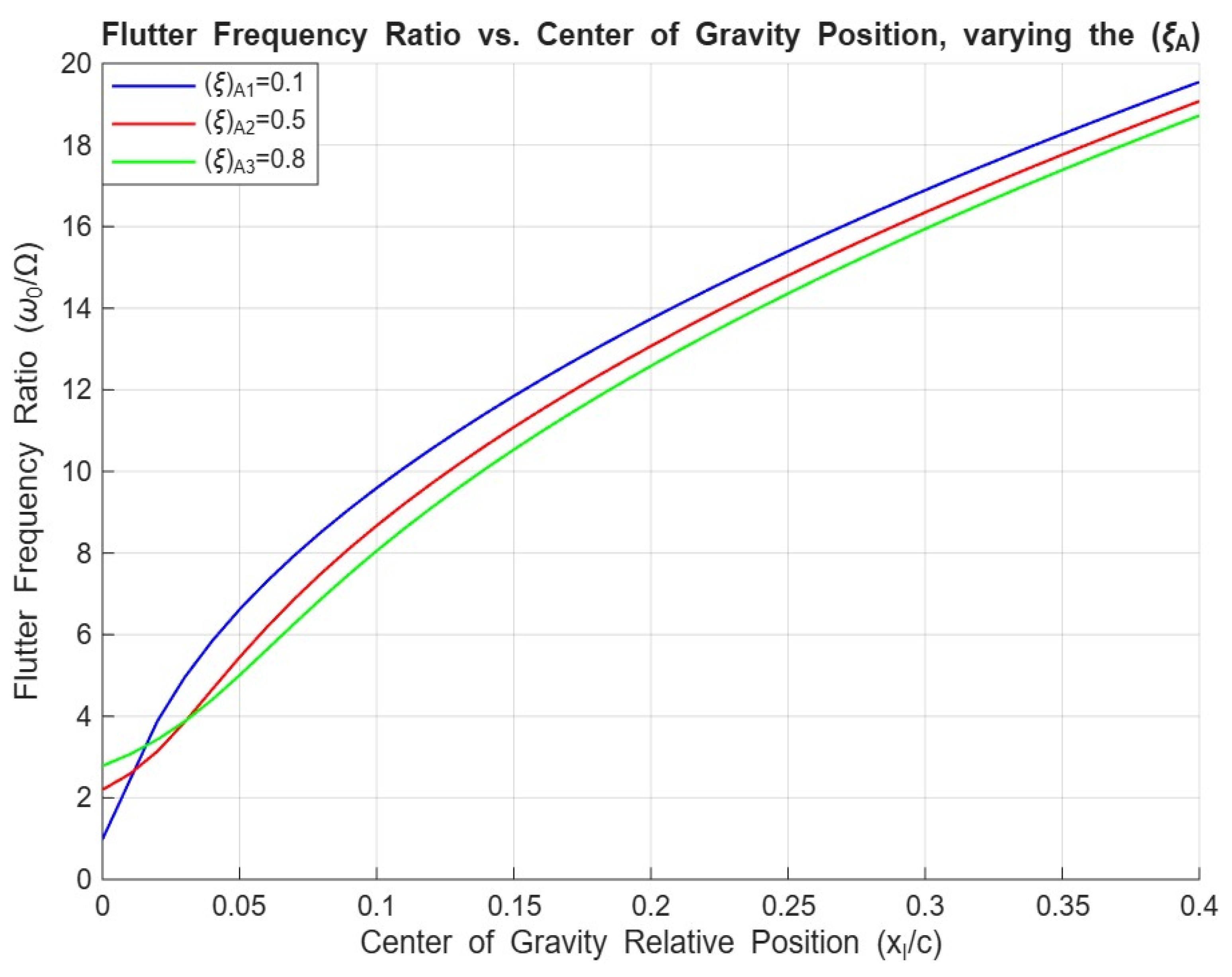
Further, the flutter stability area can be evaluated taking into consideration the varying coordinate of the aerodynamic center when the center of gravity’s relative location changes for a fixed flapping frequency . As a result, Figure 4 represents the dependencies between the flutter frequency ratio and the relative center of gravity coordinate for a fixed flapping frequency , varying the aeroelastic damping ratio (aerodynamic center relative coordinate) : to and . For every constant relative center of gravity location , an increase in the aerodynamic center coordinate will lead to a consequent rise in the flutter stability area by reducing the flutter frequency ratio . Similar results for the investigated aeroelastic system extended to forward flight are observed by Acree et al., where a rearward location of the aerodynamic center led to an increase in the flutter speed margin > 100 knots [15]. According to the represented correlations in Figure 4, nonlinear trends regarding the flutter frequency ratio and varying the center of gravity coordinates can be observed closely to the leading edge (at center of gravity relative coordinates ) for all three damping frequency ratios, possibly due to the existence of the bending and pitching moments and the interactions between them.
Figure 4.
Flutter frequency ratio vs. center of gravity location for different coordinates of the aerodynamic center and for a fixed flapping frequency .
Generally, moving the relative center of gravity location into the direction of the leading edge leads to a reduction in the flutter frequency ratio and then improves the flutter stability characteristics for all the aerodynamic center coordinates . In detail, a decrease in the relative center of gravity location from to produces an approximate reduction in the system’s stiffness equal to 79% for the aerodynamic damping ratio , declining to 62% at relative aerodynamic center coordinate . According to the evaluations provided by Singh and Chopra, the center of gravity coordinate affects the aeroelastic stability boundary by altering inertial coupling in the rotor-pylon system [13]. Similarly to the results represented in this article, according to Acree et al., small variations in the center of gravity coordinate produce an increase or decrease in the stability margin for the researched system [15]. However, if the center of gravity location is fixed at , an increase in the aerodynamic center coordinate from to and will produce a corresponding decline in the flutter frequency ratio equal to approximately 3% and 9%, respectively.
Theodorsen’s function can be applied for the estimation of the lift generated and the produced pitching moment and their corresponding coefficients when the unsteadiness of the flow exists. The unsteadiness of the flow can be represented in terms of the reduced frequency magnitude , which considers the frequency of the oscillations, the chord length and the freestream velocity. The application of Theodorsen’s function is expected to illustrate the amplitude variation and the phase difference in the examined aerodynamic parameters when the reduced frequency and then the unsteadiness of the flow change.
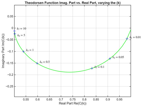
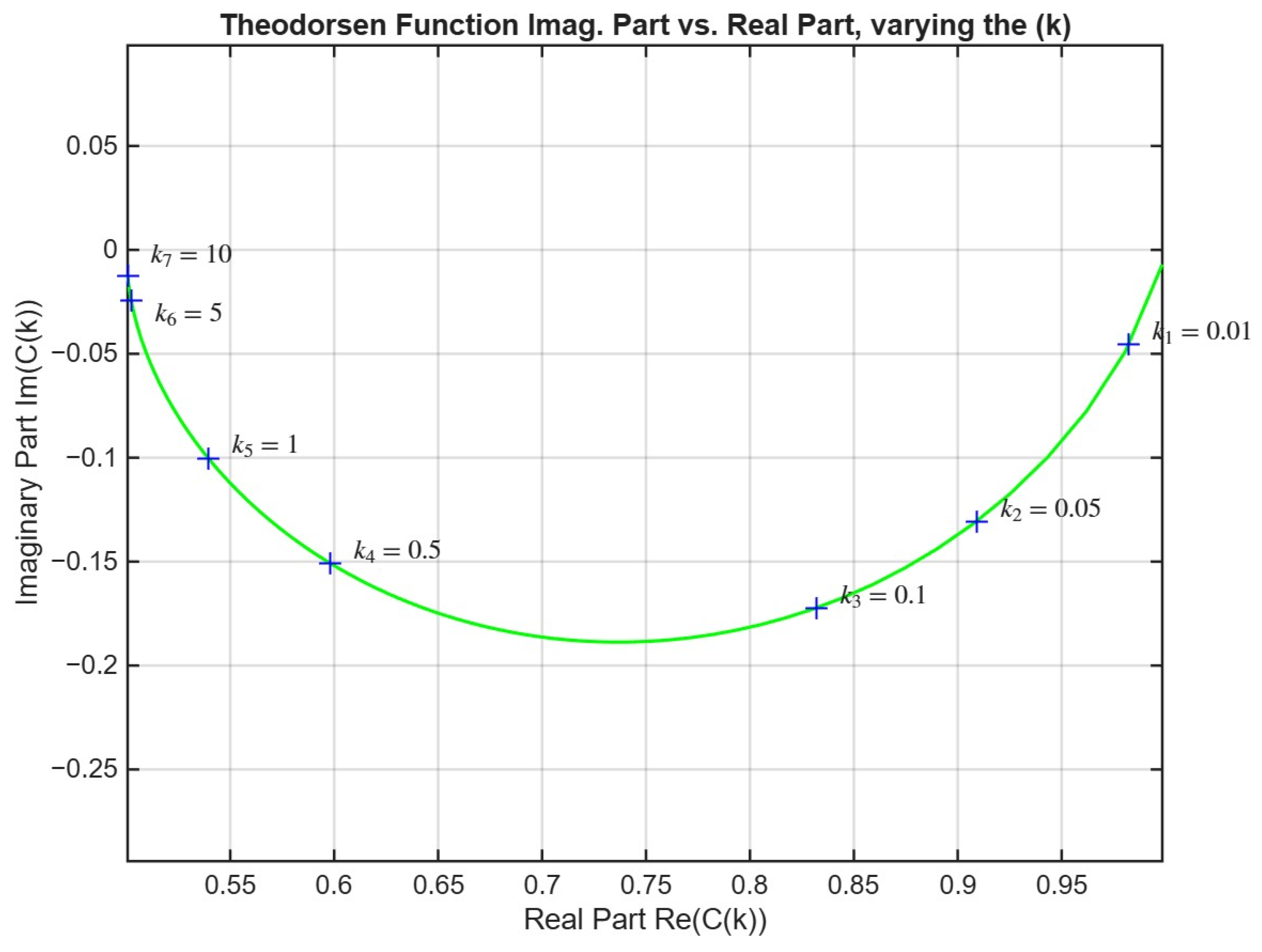
As a result, Figure 5 illustrates the dependency between the imaginary and the real parts of Theodorsen’s function, represented in a complex plane for different reduced frequency values: , , , , , and .
Figure 5.
Theodorsen’s function imaginary part vs. real part, varying the reduced frequency (k): , , , , , and .
Theodorsen’s function will represent the lift force coefficient’s variations when an oscillatory motion happens, representing the flow as two-dimensional and incompressible and can be applied in the analysis of the applied aerodynamic models. In detail, the represented arc-type dependency can be divided into several frequency regions. For the lowest reduced frequency magnitude, , the real part of Theodorsen’s function approaches 1 and the imaginary part has a magnitude of 0. For all the magnitudes of Theodorsen’s function in the low-frequency region, the expected flow conditions around the elements of the blade are steady state. When Theodorsen’s function imaginary part continues to decrease to the point where it reaches its minimum at (at reduced frequency k ), the maximum phase divergence between the motion and the aerodynamic response will be expected. Moreover, if the reduced frequency magnitude continues to increase to the maximum represented value , the imaginary part approaches 0 at , and the motion’s unsteadiness becomes more prominent.
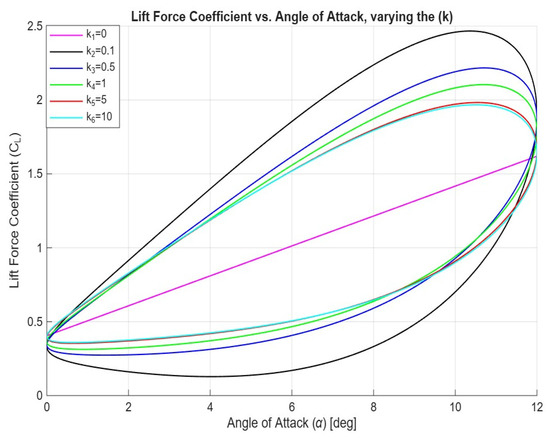
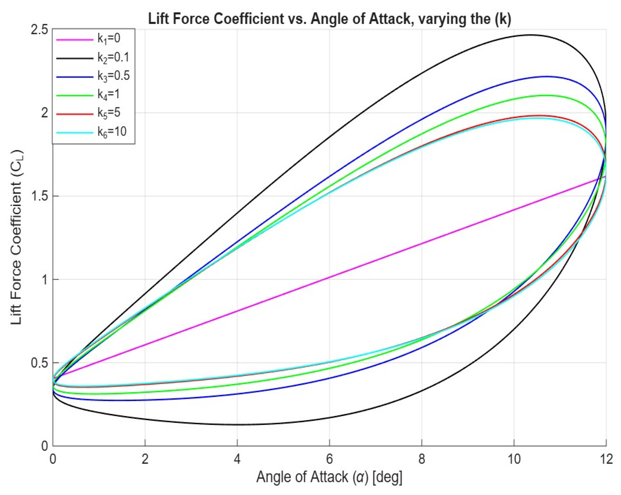
Figure 6 represents the variations in the lift force coefficient with respect to the angle of attack when the reduced frequency varies:, , , , and . In detail, the illustrated dependencies deliver a description of the rotor’s behavior when the flutter phenomenon happens, described as a variation in the lift force coefficient with the angle of attack during unsteady motions incorporating Theodorsen’s function. The reduced frequency represents the rotor’s oscillations with respect to the flow, including the unsteadiness in the flow.
Figure 6.
Lift force coefficient vs. angle of attack , varying the reduced frequency (k): , , , , and
When the reduced frequency magnitude , the lift curve variation with the angle of attack follows a normal linear trend, without high-frequency oscillations. The lift curve slope is proportional to the aerodynamic derivative of the lift force coefficient with respect to the angle of attack and the corresponding change in the angle of attack magnitude up to the stall angle.
For the linear dependency, no phase lag between the lift force coefficient and the angle of attack is observed. However, an increase in the reduced frequency magnitude produces an oscillatory type of response concerning the lift force coefficient variation with respect to the angle of attack , following an elliptical path. When the reduced frequency magnitude starts to increase from to the lift force coefficient develops a phase deviation considering the angle of attack magnitude , possibly due to the inability of the flow to reach a steady state during the increasing blades’ oscillations. For the high reduced frequency region, the curves that describe the lift force coefficient over the angle of attack become highly elliptical due to the presence of the unsteady aerodynamic phenomenon, and the increase in the phase difference between the coefficient of lift and the angle of attack becomes more prominent. For the reduced frequencies , the lift curve paths become closer to each other and behave as the curves of an infinite magnitude of . In detail, the curves become horizontal ellipses as the phase difference becomes closer to 90°, and as a result, the lift force coefficient becomes less dependent on the angle of attack variations and highly dependent on the existing accelerations. Moreover, at high reduced frequency magnitudes , the generation of lift force is compromised due to the presence of oscillations, which do not allow the wake to develop a circulation around the airfoil, and the result can be observed as a decline in the lift force coefficient magnitude . According to Singh and Chopra, the lift force coefficient variation becomes oscillatory during the instability and exhibits a critical phase lag relative to blade motion [13]. As a result, the flutter happens when the phase-shifted lift transitions from dissipating energy to supplying energy to the structural motion and produces an aeroelastic response [13].
5. Conclusions
In conclusion, this article represented the estimation of the aeroelastic flutter stability characteristics of a helicopter rotor, which operated in the hovering regime. As a result of the applied analytical study, an evaluation of the flutter stability boundaries was performed by solving the flutter stability equations, considering several operational parameters, a method that is widely applicable when investigating the aeroelastic stability of helicopter rotors [12,13,14]. The results are generally illustrated in terms of frequency behavior, with a similar approach to the one already represented in [7]. Eventually, the estimation of the flutter stability ratio as a function of the center of gravity relative position , when the relative distance from the ground surface varied from to and , was conducted. According to the represented results, an increase in the flutter stability ratio for every constant relative distance from the ground led to a rise in the flutter stability zone. Conversely, for every constant relative center of gravity coordinate , a decrease in the relative distance from the helicopter’s rotational plane produced a decline in the flutter stability area. For instance, when the center of gravity relative coordinate , a change in the relative distance from the helicopter’s rotational plane to the ground from to and produced an additional rise in the system’s stiffness equal to 8.3% and 9.8%, which is a considerably higher increase in comparison to the stiffness when the center of gravity relative coordinate . Additionally, the effect of the aerodynamic center’s location on the correlation between the flutter stability ratio and the relative center of gravity coordinate was evaluated. As a result, an increase in the aerodynamic center’s relative coordinate produced a decline in the flutter stability ratio and then increased the flutter stability area. A rearward location of the aerodynamic center was found to improve the stability margin in forward flight > 100 knots [15]. Moreover, for the aerodynamic center’s location a decline in the relative center of gravity coordinate from to led to an approximate reduction in the stiffness of the system equal to 79%, declining to 62% at . The center of gravity coordinate variation affects the aeroelastic stability boundary [13]. Small variations in the center of gravity coordinate led to an increase in or a decrease in the stability margin [15]. The application of Theodorsen’s function, when the reduced frequency , which considers the unsteadiness of the flow, varies, was conducted. In detail, the representation of the imaginary and real parts of Theodorsen’s function, when the reduced frequency changed, showed that for the lowest magnitude of the reduced frequency, , the real part approaches 1 and the imaginary part 0. Consequently, for the low-frequency region of Theodorsen’s function, the expected flow conditions were steady state. The maximum phase divergence between the motion and the aerodynamic response was observed at the minimum of Theodorsen’s function at Moreover, when the reduced frequency continued to increase towards its maximum regarded magnitude , the motion’s unsteadiness became even more prominent. It was found that the lift force coefficient variation becomes oscillatory during the instability and exhibits a critical phase lag relative to blade motion and could produce an aeroelastic response [13]. Theodorsen’s function has been applied for the evaluation of the variations in the lift force coefficient over the angle of attack when the reduced frequency varies. For the case of a reduced frequency , the lift curve force coefficient variation with the angle of attack followed a normal linear trend, without high-frequency oscillations. In detail, no phase difference was observed for the linear dependency between the lift force coefficient and the angle of attack . However, when the reduced frequency value increased, an oscillatory type of response regarding the lift force coefficient variation over the angle of attack existed and followed an elliptical path. When the reduced frequency magnitude continued to increase to the magnitudes , the phase deviation rose, and the curves behaved as the curves of an infinite magnitude of the reduced frequency
Funding
The author of this paper would like to thank the Research and Development Sector of the Technical University of Sofia for funding the publication of this article.
Institutional Review Board Statement
Not applicable.
Informed Consent Statement
Not applicable.
Data Availability Statement
The data contained within the article are available upon request.
Conflicts of Interest
The author declares no conflicts of interest.
References
- Johnson, W. Rotorcraft Aeromechanics; Cambridge University Press: New York, NY, USA, 2013. [Google Scholar]
- Leishman, G. Introduction to Aerospace Flight Vehicles; Embry—Riddle Aeronautical University: Daytona Beach, FL, USA, 2023. [Google Scholar]
- Kreshock, A.R.; Thornburgh, R.P.; Kang, H.; Yeo, H. Experimental and analytical comparison of stiff and flexible rotor blades for whirl-flutter stability. In Proceedings of the 50th European Rotorcraft Forum, Marseille, France, 10–12 September 2024. [Google Scholar]
- McKechnie, M.; Barakos, G. Aeroelastic analysis of propeller blades at stall flutter onset. Aeronaut. J. 2025, 129, 3446–3466. [Google Scholar] [CrossRef] [Scilit]
- Sutherland, J.R.; Tsai, F.; Datta, A. Whirl Flutter Test of the Maryland Tiltrotor Rig: Swept-Tip Blades. In Proceedings of the AIAA SCITECH 2022 Forum, San Diego, CA, USA, 3–7 January 2022. [Google Scholar]
- Delgado, X.M.; Datta, A. High Speed Whirl Flutter Tests and Predictions of Swept—Tip Tiltrotor Blades. In Proceedings of the AIAA SCITECH 2025 Forum, Orlando, FL, USA, 6–10 January 2025. [Google Scholar]
- Arnold, J. Flutter assessment of a rotor blade in hover based on indicial aerodynamics considering blade aerofoil, rotor inflow and wake periodicity. Aeronaut. J. 2025, 129, 593–608. [Google Scholar] [CrossRef] [Scilit]
- Krüger, W.R. Multibody Analysis of Whirl Flutter Dynamics on a Tiltrotor Wind Tunnel Model. In Proceedings of the International Forum on Aeroelasticity and Structural Dynamics (IFASD 2009), Seattle, WA, USA, 21–25 June 2009. [Google Scholar]
- Cocco, A.; Savino, A. Tiltrotor Whirl-Flutter Assessment by Multifidelity Aerodynamic Models. In Proceedings of the AIAA SciTech Forum and Exposition 2024, Orlando, FL, USA, 8–12 January 2024. [Google Scholar]
- Böhnisch, N.; Kantzidis, P.; Masarati, P.; Muscarello, V. Assessment of Aerodynamic Torque on Propeller Whirl Flutter and Its Control. J. Aircr. 2025, 62, 1490–1503. [Google Scholar] [CrossRef] [Scilit]
- Kunz, D.L. Analysis of Proprotor Whirl Flutter: Review and Update. J. Aircr. 2005, 42, 172–178. [Google Scholar] [CrossRef] [Scilit]
- Shen, J.; Chopra, I. Aeroelastic Stability of Smart Trailing-Edge Flap Helicopter Rotors. In Proceedings of the AIAA Applied Aerodynamics Conference, Anaheim, CA, USA, 11–14 June 2001. [Google Scholar]
- Singh, B.; Chopra, I. Whirl Flutter Stability of Two-Bladed Proprotor/Pylon Systems in High Speed Flight. J. Am. Helicopter Soc. 2003, 48, 99–107. [Google Scholar] [CrossRef] [Scilit]
- Hathaway, E.L.; Gandhi, F. Tiltrotor Whirl Flutter Alleviation Using Actively Controlled Wing Flaperons. AIAA J. 2006, 44, 2524–2534. [Google Scholar] [CrossRef] [Scilit]
- Acree, C.W., Jr.; Peyran, R.J.; Johnson, W. Rotor Design Options for Improving XV-15 Whirl-Flutter Stability Margins; NASA Technical Publication 2004, NASA/TP—2004—212262; Ames Research Center: Moffett Field, CA, USA, 2004. [Google Scholar]
- Tang, D.M.; Dowell, E.H. Flutter and stall response of a helicopter blade with structural nonlinearity. J. Aircr. 1992, 29, 953–960. [Google Scholar] [CrossRef] [Scilit] [PubMed]
- Mueller, J.P.; Gourinat, Y.; Ferrer, R.; Krysinski, T.; Kerdreux, B. A Numerical Study on Active Control for Tiltrotor Whirl Flutter Stability Augmentation. J. Am. Helicopter Soc. 2006, 51, 244–254. [Google Scholar] [CrossRef] [Scilit]
- Georgiev, G.; Panayotov, F.; Serbezov, V.; Todorov, M. Experimental Study of Static Characteristics of a Helicopter Rotor in Ground Effect. In Proceedings of the 11th International Scientific Conference “TechSys 2022”—Engineering, Technologies and Systems, Plovdiv, Bulgaria, 26–28 May 2022. [Google Scholar]
- Georgiev, G. Blade element–momentum aerodynamic model of a helicopter rotor operating at low-Reynolds numbers in ground effect. Aviat. J. 2025, 29, 71–81. [Google Scholar] [CrossRef] [Scilit]
- Georgiev, G. Helicopter Rotor Aerodynamic Characteristics in Ground Effect: Numerical Study. Eng. Proc. 2025, 100, 13. [Google Scholar] [CrossRef] [Scilit]
Disclaimer/Publisher’s Note: The statements, opinions and data contained in all publications are solely those of the individual author(s) and contributor(s) and not of MDPI and/or the editor(s). MDPI and/or the editor(s) disclaim responsibility for any injury to people or property resulting from any ideas, methods, instructions or products referred to in the content. |
© 2026 by the author. Licensee MDPI, Basel, Switzerland. This article is an open access article distributed under the terms and conditions of the Creative Commons Attribution (CC BY) license.