Emissions and Dynamics: The Role of Software in Similar Automotive Platforms †


Abstract
1. Introduction
2. Materials and Methods
2.1. Different Power Output—Same Emission Standards
2.2. Same Power Output—Different Emission Standards
3. Results
4. Conclusions
Author Contributions
Funding
Institutional Review Board Statement
Informed Consent Statement
Data Availability Statement
Acknowledgments
Conflicts of Interest
Abbreviations
| ICE | Internal combustion engine |
| SI | Spark ignition |
| ECU | Engine control unit |
| VVT | Variable valve timing |
References
- Liu, Y.; Chen, H.; Li, Y.; Gao, J.; Dave, K.; Chen, J.; Li, T.; Tu, R. Exhaust and non-exhaust emissions from conventional and electric vehicles: A comparison of monetary impact values. J. Clean. Prod. 2022, 331, 129965. [Google Scholar] [CrossRef] [Scilit]
- Hlebarski, D.; Savova-Mratsenkova, M. Algorithm for expert analysis of the mechanism of the occurrence of a traffic accident involving a car and a pedestrian. AIP Conf. Proc. 2025, 3274, 060002. [Google Scholar] [CrossRef] [Scilit]
- Hartman, J. How to Tune and Modify Automotive Engine Management Systems; Motorbooks: Minneapolis, MN, USA, 2013. [Google Scholar]
- Buckland, J.H.; Cook, J. Automotive emissions control. In Proceedings of the American Control Conference 2005, Portland, OR, USA, 8–10 June 2005. [Google Scholar] [CrossRef] [Scilit]
- Cook, J.A.; Sun, J.; Grizzle, J.W. Opportunities in automotive powertrain control applications. In Proceedings of the International Conference on Control Applications, Glasgow, UK, 18–20 September 2002; Volume 1, pp. xlii–xlli. [Google Scholar] [CrossRef] [Scilit]
- Wasserburger, A.; Didcock, N.; Hametner, C. Efficient real driving emissions calibration of automotive powertrains under operating uncertainties. Eng. Optim. 2023, 55, 140–157. [Google Scholar] [CrossRef] [Scilit]
- Kruse, T.; Kurz, S.; Lang, T. Modern Statistical Modeling and Evolutionary Optimization Methods for the Broad Use in ECU Calibration. IFAC Proc. Vol. 2010, 43, 739–743. [Google Scholar] [CrossRef] [Scilit]
- Prati, M.; Costagliola, M.; Rapone, M. Unregulated Emissions of Euro I, II and III Gasoline Cars; SAE Technical Paper 2005-24-025; SAE: Warrendale, PA, USA, 2005. [Google Scholar] [CrossRef] [Scilit]
- Saliev, D. Clearance speed study for intergreen time determination. IOP Conf. Ser. Mater. Sci. Eng. 2020, 878, 012048. [Google Scholar] [CrossRef] [Scilit]
- Tashev, A.; Ambarev, K.; Paitakov, N.; Nikolov, V. Experimental Investigation of Economic Parameters, Noise and Exhaust Emissions, and Thermal Behavior of a Spark-Ignition Engine Operating with CNG. In Proceedings of the 2025 10th International Conference on Energy Efficiency and Agricultural Engineering (EE&AE), Stara Zagora, Bulgaria, 5–7 November 2025; IEEE: Piscataway, NJ, USA, 2025; pp. 1–6. [Google Scholar] [CrossRef] [Scilit]
- Dimitrov, E.; Tashev, A. CNG effect on performance parameters of diesel engine operated on dual-fuel mode. AIP Conf. Proc. 2022, 2449, 050009. [Google Scholar] [CrossRef] [Scilit]
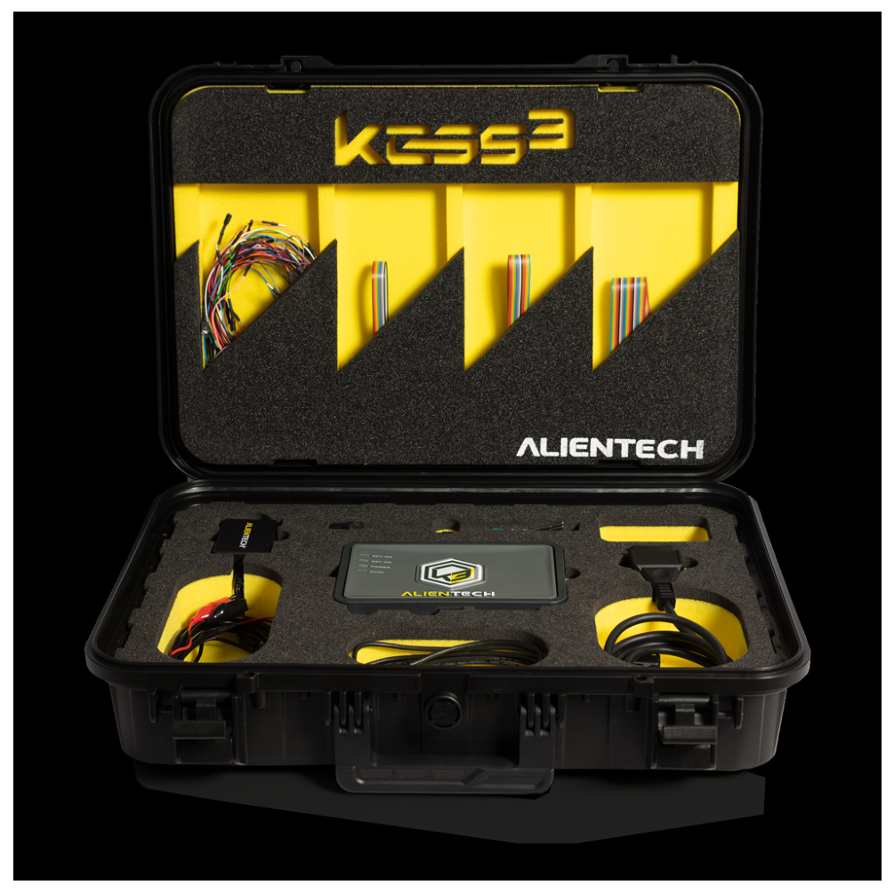
- Available online: https://www.alientech-tools.com/kess3/ (accessed on 30 April 2026).
- Martín-Sánchez, G.; Machens, C.K.; Podlaski, W.F. Three types of remapping with linear decoders: A population-geometric perspective. PLoS Comput. Biol. 2025, 21, e1013545. [Google Scholar] [CrossRef] [Scilit] [PubMed]
- Hughes, P. Understanding ECU Remapping and Tuning: Techniques and Benefits. J. Automot. Eng. 2021, 64, 342–356. [Google Scholar]
- Sinigaglia, T.; Martins, M.E.S.; Siluk, J.C.M. Technological evolution of internal combustion engine vehicle: A patent data analysis. Appl. Energy 2022, 306, 118003. [Google Scholar] [CrossRef] [Scilit]
- Mladenov, G.; Kuzmanov, N.; Hristov, V. Research on and Analysis of Brake Fluid Impact on Brake System Performance. Eng. Proc. 2025, 100, 27. [Google Scholar] [CrossRef] [Scilit]
- Heydari, J. Remapping and ECU Tuning Techniques in Modern Vehicles: Benefits, Risks, and Future Trends. Res. Innov. 2025, 2, 85–91. [Google Scholar] [CrossRef] [Scilit]
- Perez, L.; O’Brien, J. Impact of ECU Remapping on Vehicle Emissions and Legal Compliance. Environ. Policy Rev. 2020, 30, 475–490. [Google Scholar]
- Zhao, L.; Chen, W. Impact of ECU Remapping on Engine Durability and Safety. Int. J. Mech. Eng. 2019, 65, 455–468. [Google Scholar]
- Davies, R.; Watts, K. Emissions and ECU Remapping: An In-Depth Analysis. Environ. Impact J. 2019, 52, 28–34. [Google Scholar]
- Hristov, V.D.; Saliev, D.N.; Slavov, D.V. Artificial Intelligence Systems for Warehouses Stocks Control. In Proceedings of the 2022 8th International Conference on Energy Efficiency and Agricultural Engineering (EE&AE), Ruse, Bulgaria, 30 June–2 July 2022; IEEE: Piscataway, NJ, USA, 2022; pp. 1–5. [Google Scholar] [CrossRef] [Scilit]
- Kakaee, A.H.; Mashadi, B.; Ghajar, M. A novel volumetric efficiency model for spark ignition engines equipped with variable valve timing and variable valve lift Part 1: Model development. Proc. Inst. Mech. Eng. Part D J. Automob. Eng. 2016, 231, 175–191. [Google Scholar] [CrossRef] [Scilit]
- Directive 98/69/EC. Available online: https://eur-lex.europa.eu/eli/dir/1998/69/oj/eng (accessed on 30 April 2026).
- Regulation (EC) No 715/2007. Available online: https://eur-lex.europa.eu/eli/reg/2007/715/oj/eng (accessed on 30 April 2026).
- Commission Directive 2002/80/EC. Available online: https://eur-lex.europa.eu/eli/dir/2002/80/oj/eng (accessed on 30 April 2026).
- Commission Regulation (EC) No 692/2008. Available online: https://eur-lex.europa.eu/eli/reg/2008/692/oj/eng (accessed on 30 April 2026).
- Mårtensson, J.; Flärdh, O. Modeling the Effect of Variable Cam Phasing on Volumetric Efficiency, Scavenging and Torque Generation; SAE Technical Papers; SAE: Warrendale, PA, USA, 2010. [Google Scholar] [CrossRef] [Scilit]
- Genç, A.U.; Glover, K. Identification of the Twin Independent Variable Cam Timing Engines for AFR Control. J. Dyn. Syst. Meas. Control. 2005, 127, 589–600. [Google Scholar] [CrossRef] [Scilit]
- Stefanopoulou, A.G.; Cook, J.A.; Grizzle, J.W.; Freudenberg, J.S. Control-Oriented Model of a Dual Equal Variable Cam Timing Spark Ignition Engine. J. Dyn. Syst. Meas. Control. 1998, 120, 257–266. [Google Scholar] [CrossRef] [Scilit]






| Engine Type | VAG EA211 Inline-Four Petrol Engines CJZC | VAG EA211 Inline-Four Petrol Engines CJZD |
|---|---|---|
| Design & principle | Four-cylinder in-line engine, four-stroke Otto cycle, turbocharged, gasoline direct injection | Four-cylinder in-line engine, four-stroke Otto cycle, turbocharged, gasoline direct injection |
| 1197 cm3 | 1197 cm3 | |
| 66 kW (90 hp)/4400–5400 rpm | 81 kW (110 hp)/4600–5600 rpm | |
| Max. torque at speed | 160 Nm/1400–3500 rpm | 175 Nm/1400–4000 rpm |
| 10.5:1 | 10.5:1 | |
| Max. engine speed | 6300 rpm | 6300 rpm |
| Dual overhead camshaft with variable valve timing | Dual overhead camshaft with variable valve timing | |
| Camshaft drive | Timing belt | Timing belt |
| 71 mm | 71 mm | |
| Piston stroke | 75.6 mm | 75.6 mm |
| Intake manifold | Plastic inlet manifold and charge air cooler | Plastic inlet manifold and charge air cooler |
| BOSCH MED17.5.5 | BOSCH MED17.5.5 | |
| Unleaded petrol, min. 95 ROZ | Unleaded petrol, min. 95 ROZ | |
| Exhaust after treatment | Three-way catalytic converter with one step-type Lambda probe before and one after the catalytic converter which is positioned directly behind the turbocharger in an L shape to minimize space and achieve maximum temperature rapidly. Underbody Catalyst: A second three-way catalytic converter located under the vehicle to ensure compliance with emissions standards under heavy loads. | Three-way catalytic converter with one step-type Lambda probe before and one after the catalytic converter which is positioned directly behind the turbocharger in an L shape to minimize space and achieve maximum temperature rapidly. Underbody Catalyst: A second three-way catalytic converter located under the vehicle to ensure compliance with emissions standards under heavy loads. |
| Euro 5B | Euro 5B | |
| Lubrication system | Oil pressure; engine oil cooler; piston crown spray cooling | Oil pressure; engine oil cooler; piston crown spray cooling |
| Liquid, dual-circuit cooling system, electronically controlled | Liquid, dual-circuit cooling system, electronically controlled | |
| Ignition system | Ignition coil on spark plug; high-energy ignition; cylinder-selective knock detection | Ignition coil on spark plug; high-energy ignition; cylinder-selective knock detection |
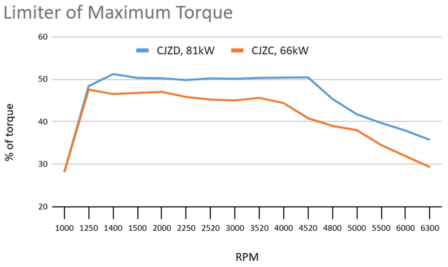
| Limiter of Maximum Torque, CJZC, 66 kW | |
|---|---|
| RPM | % |
| 1000 | 28.11 |
| 1250 | 47.55 |
| 1400 | 46.50 |
| 1500 | 46.76 |
| 2000 | 47.00 |
| 2250 | 45.82 |
| 2520 | 45.17 |
| 3000 | 44.99 |
| 3520 | 45.58 |
| 4000 | 44.36 |
| 4520 | 40.80 |
| 4800 | 38.98 |
| 5000 | 38.00 |
| 5500 | 34.50 |
| 6000 | 31.87 |
| 6300 | 29.29 |
| Limiter of Maximum Torque, CJZD, 81 kW | |
|---|---|
| RPM | % |
| 1000 | 28.11 |
| 1250 | 48.36 |
| 1400 | 51.2 |
| 1500 | 50.31 |
| 2000 | 50.2 |
| 2250 | 49.78 |
| 2520 | 50.19 |
| 3000 | 50.1 |
| 3520 | 50.29 |
| 4000 | 50.37 |
| 4520 | 50.41 |
| 4800 | 45.34 |
| 5000 | 41.73 |
| 5500 | 39.68 |
| 6000 | 37.88 |
| 6300 | 35.71 |
| Engine Type | General Motors 1.8L I-4 Fam1 Gen3 Z18XER | General Motors 1.8L I-4 Fam1 Gen3 A18XER |
|---|---|---|
| Design & principle | Four-cylinder in-line engine, four-stroke Otto engine | Four-cylinder in-line engine, four-stroke Otto engine |
| 1796 cm3 | 1796 cm3 | |
| 103 kW (140 hp) at 6300 rpm | 103 kW (140 hp) at 6300 rpm | |
| Max. torque at speed | 175 Nm at 3800 rpm | 175 Nm at 3800 rpm |
| 10.5:1 | 10.5:1 | |
| Max. engine speed | 6500 rpm | 6500 rpm |
| 2 top-mounted, double continuous phase-adjustable (DCVCP) | 2 top-mounted, double continuous phase-adjustable (DCVCP) | |
| Camshaft drive | Timing belt | Timing belt |
| 80.5 mm | 80.5 mm | |
| Piston stroke | 88.2 mm | 88.2 mm |
| Intake manifold | Plastic, two-stage suction length adjustment | Plastic, two-stage suction length adjustment |
| Siemens Simtec 75.1 | AcDelco E83 | |
| 91/95/98 RON | 91/95/98 RON | |
| Exhaust aftertreatment | Close-coupled 3-way catalytic converter with 2 lambda sensors | Close-coupled 3-way catalytic converter with 2 lambda sensors |
| Euro 4 | Euro 5 | |
| Lubrication system | Oil pressure; engine oil cooler; piston crown spray cooling | Oil pressure; engine oil cooler; piston crown spray cooling |
| Liquid, closed circuit; electronically controlled | Liquid, closed circuit; electronically controlled | |
| Ignition system | Ignition coil on spark plug; high-energy ignition; cylinder-selective knock detection | Ignition coil on spark plug; high-energy ignition; cylinder-selective knock detection |
| Parameter | Euro 4 (Petrol) | Euro 5 (Petrol) |
|---|---|---|
| Relevant EU Directives/Regulations | Directive 98/69/EC [23] & Directive 2002/80/EC [25]—set Euro 4 emission limits (for cars and light vans) | Regulation (EC) No 715/2007 [24] together with Regulation (EC) No 692/2008 [26]—set Euro 5 emission limits (and later amendments) |
| Date of Introduction—Type Approval | 1 January 2005 (new type approvals) | 1 September 2009 (new type approvals) |
| Date of Introduction—All New Registrations | 1 January 2006 | 1 January 2011 (typical timing after approval) |
| CO (Carbon Monoxide) | 1.0 g/km | 1.0 g/km |
| HC (Unburned Hydrocarbons) | 0.10 g/km | 0.10 g/km |
| NOx (Nitrogen Oxides) | 0.08 g/km | 0.06 g/km |
| PM (Particulate Matter) | Not regulated for port injection | 0.005 g/km only applicable to direct-injection petrol (not applicable to port-injected engines) |
| PN (Particle Number) | Not regulated | 6.0 × 10¹¹ #/km only for direct-injection petrol under Euro 5b (no limit for port injection) |
| Engine Type | Eng.Sped | Oil Temp | CO2 | HC | Nox | λ | O2 | CO | Exhaust Gas |
|---|---|---|---|---|---|---|---|---|---|
| rpm | °C | % | ppm Vol | ppm Vol | - | % | % | deg C | |
| Z18XER | 802 | 80 | 14.40 | 37 | 5 | 1.020 | 0.61 | 0.09 | 42 |
| A18XER | 800 | 81 | 14.60 | 26 | 5 | 1.020 | 0.59 | 0.06 | 42 |
| CJZC | 750 | 75 | 14.70 | 28 | 3 | 0.990 | 0.00 | 0.08 | 42 |
| CJZD | 750 | 73 | 14.70 | 27 | 3 | 0.990 | 0.00 | 0.08 | 41 |
Disclaimer/Publisher’s Note: The statements, opinions and data contained in all publications are solely those of the individual author(s) and contributor(s) and not of MDPI and/or the editor(s). MDPI and/or the editor(s) disclaim responsibility for any injury to people or property resulting from any ideas, methods, instructions or products referred to in the content. |
© 2026 by the authors. Licensee MDPI, Basel, Switzerland. This article is an open access article distributed under the terms and conditions of the Creative Commons Attribution (CC BY) license.
Share and Cite
Konakchiev, H.; Damyanov, I.; Miletiev, R. Emissions and Dynamics: The Role of Software in Similar Automotive Platforms. Eng. Proc. 2026, 150, 14. https://doi.org/10.3390/engproc2026150014
Konakchiev H, Damyanov I, Miletiev R. Emissions and Dynamics: The Role of Software in Similar Automotive Platforms. Engineering Proceedings. 2026; 150(1):14. https://doi.org/10.3390/engproc2026150014
Chicago/Turabian StyleKonakchiev, Hristo, Iliyan Damyanov, and Rosen Miletiev. 2026. "Emissions and Dynamics: The Role of Software in Similar Automotive Platforms" Engineering Proceedings 150, no. 1: 14. https://doi.org/10.3390/engproc2026150014
APA StyleKonakchiev, H., Damyanov, I., & Miletiev, R. (2026). Emissions and Dynamics: The Role of Software in Similar Automotive Platforms. Engineering Proceedings, 150(1), 14. https://doi.org/10.3390/engproc2026150014