


Abstract
Roman artillery represents a key element of ancient military technology, reflecting the advanced level of technical knowledge achieved in the late Republican and early Imperial periods. However, the operational capabilities and the design methodology of these weapons are not adequately described in historical references. This study investigates the launch performance of Roman Scorpio catapult by integrating archeological evidence from impact craters on Pompeii’s northern walls with analytical modeling of torsion-spring behavior. The present study determines the required release velocity of an arrow capable of creating impact craters reported by applying ballistic and aerodynamic analytical models. Historically cited rope materials for torsion springs are evaluated using experimentally reported mechanical properties and geometric constraints. The integrated analysis highlights how material selection and drag-related energy losses influence projectile velocity, supporting the plausibility of the proposed catapult configuration and offering highlights into ancient artillery design.
1. Introduction
During the period of political instability in the late Roman Republic, the Roman general Lucius Cornelius Silla laid siege to Pompeii in 89 BC. During this military campaign, various Roman torsion-based artillery systems were deployed, including stone-throwing ballistae and arrow-shooting engines, to weaken the city’s defenses and inflict casualties on the defending forces. A substantial number of these projectiles missed their target and impacted on the fortified walls of Pompeii, producing craters on the masonry surfaces, likely because of inaccuracies in targeting, projectile release angle, or the battlefield conditions [1]. These impact craters were buried beneath volcanic ash and eruption debris, because of the eruption of Mount Vesuvius in 79 AD, which prevented damage to the wall surfaces from eventual weathering [2]. These preserved craters provide a unique opportunity to measure the devastating power of Roman artillery. Archeological surveys conducted along the northern walls have revealed a large concentration of such cavities, suggesting their association with Silla’s siege. Their geometric features provide measurable proof of the impact conditions of spherical stones and arrows [3]. In a more recent survey campaign along this section of the wall, Rossi et al. identified a recurring pattern of closely packed groups of craters sharing common morphological characteristics [4]. The authors suggest that these patterns resulted from consecutive shots fired by a multi-launcher or Polybolos. Some details of this machine have been preserved and conveyed to us through the works of Philon, translated into German by Erwin A. Schramm [5], and later into English by Eric William Marsden [6]. Although research on automatic loading and rapid launch mechanisms is limited, these observations underscore the importance of revisiting previous attempts at designing and calculating the key mechanisms of this ancient machinery, with torsion engines being the most significant.
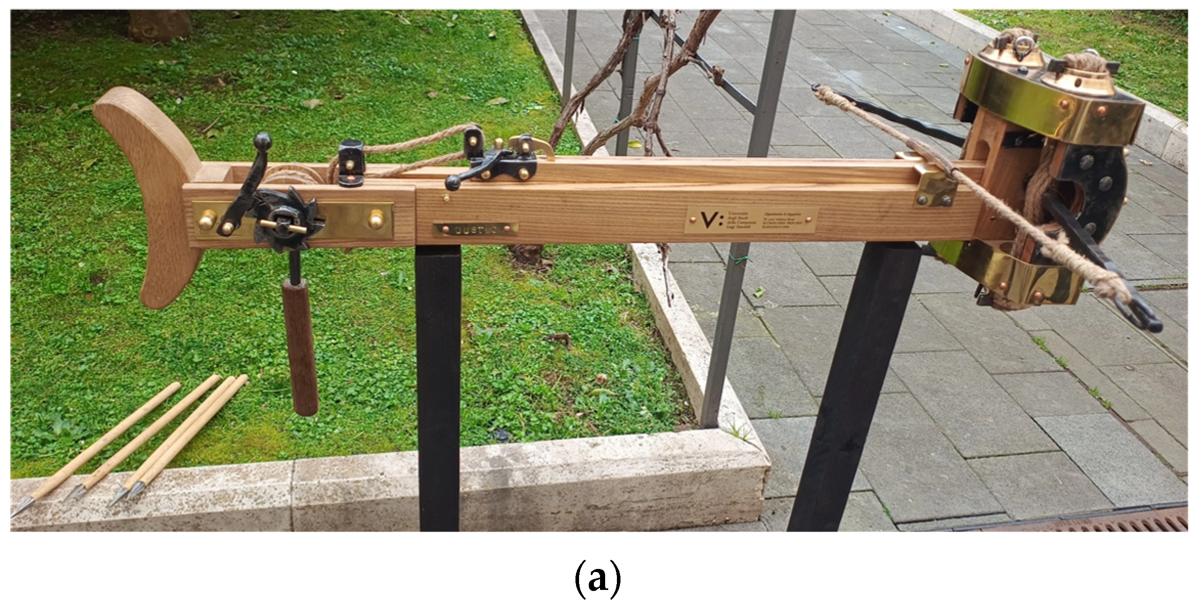
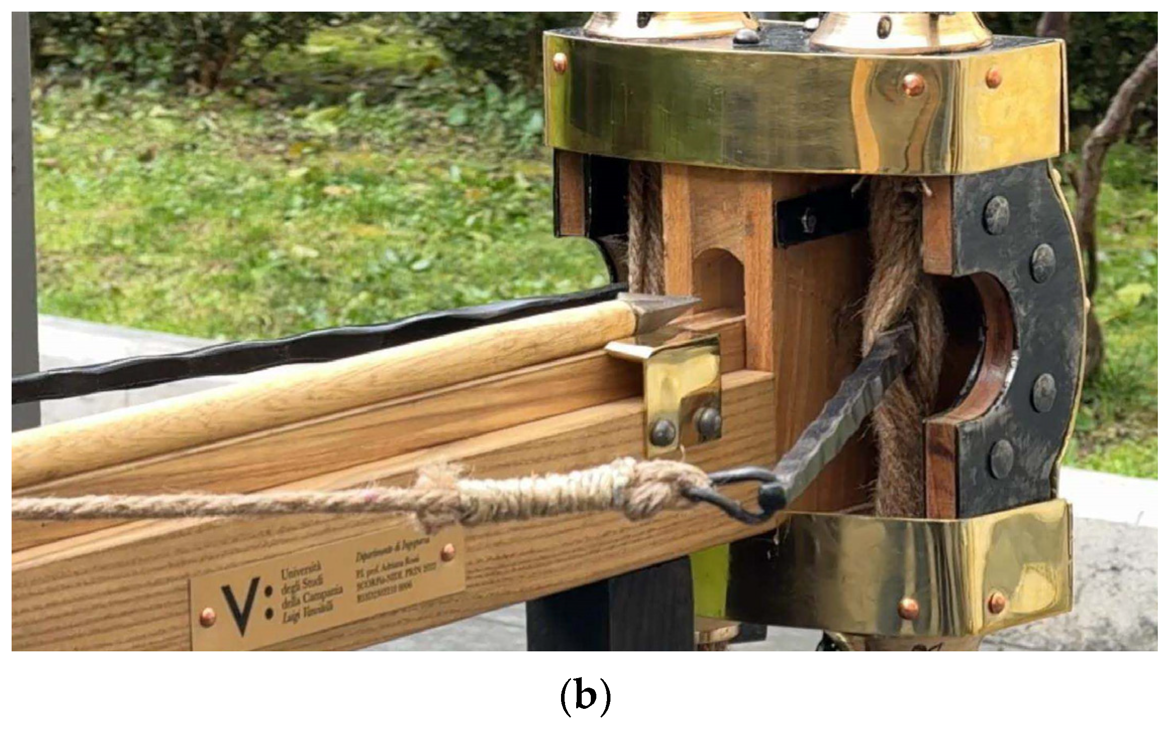
Existing research on ancient Roman artillery has primarily concentrated on the reconstruction of torsion engines, as shown in Figure 1; detailing the design criteria, assumptions and construction procedures [6,7,8,9]. They used empirical relationships reported by ancient designers such as Philon, Vitruvius, and Heron to estimate machine component dimensions that are functions of the torsion spring modulus diameter (D) [6,8]. While spring diameter is estimated by using a spherical mass–diameter relationship ( where m is mass of the projectile in minae and D is diameter of spring in digits) and arrow length–diameter equation (D = S/9 where S is the length of the arrow). Although, they offer little insight into the machine’s performance such as the amount of energy stored in torsion springs, the projectile release velocity or the impact velocity from it.
Only a limited number of studies have attempted to estimate the maximum projectile release velocity and firing range achievable by torsion engines by considering mechanical properties for spring material [10,11]. Nonetheless, the available literature is limited to the choice of female hair [11] as the spring material without thoroughly comparing it with other materials mentioned in historical literature. To address these limitations, the present study adopts an analytical approach to estimate the elastic energy stored in the torsion springs of Roman Scorpio catapults and the achievable projectile release velocity and then compares it to the required projectile release velocity.
In an earlier analytical reconstruction of a Roman Scorpio dart by Russo and Rossi, the authors employed a simplified energy-balance method to estimate impact conditions from measured crater geometry and arrowhead dimensions [12]. The quadrangular crater in Nocera Tuff (a specific Gray Campania Tuff) had a side of approximately 30 mm, with shallow normal penetration idealized as a truncated pyramid yielding a pulverized-rock volume of 9–12 cm3. Deformation work was calculated using an assumed rupture stress of about 100 kg/cm2 (≈1000 N/cm2), resulting in N·m. For a dart mass of ≈0.15 kg (93 g iron tip, ≈150 g total including wooden shaft) and a 100 m engagement distance, equating to kinetic energy gave an order-of-magnitude impact velocity of roughly 109 m/s. This direct reverse-engineering from Vitruvian principles and crater evidence marked an early step in quantifying Roman artillery potency.
To further investigate this manner, the authors previously applied a calibrated finite element (FE) framework to assess the structural integrity of Pompeii’s Nocera Tuff fortifications under Roman artillery fire, using preserved craters and assuming a dart similar to previous studies as physical benchmarks. The aim is to use reverse engineering and employ the measured crater geometries to analyze the relation between impact velocity and the geometry of the projectile on the indentation depth and characteristics [13]. High-resolution photogrammetric models provided crater geometry (≈120 mm penetration, ≈140 mm projectile diameter), which was converted into simplified NURBS-based solids and used to define the reference impact scenario. Gray Campania Tuff was characterized from the literature (UCS ≈ 4.5–5 MPa, E up to ≈3.5 GPa, density ≈ 2300 kg/m3) and modeled via a Concrete Damage Plasticity (CDP) formulation with distinct compression–tension laws, damage evolution, and quiet-boundary infinite elements to control wave reflections. The basalt ball projectile (D = 140 mm) was represented as linear elastic (Es ≈ 60 GPa, UCS ≈ 60 MPa), while the dart combined a rigid iron head and deformable tuff substrate, with separate mesh strategies for spherical and sharp-edged contact. Axisymmetric and 3D explicit dynamic models were used to run mesh-convergence studies (D/100 for the ball, S/50 for the dart) and velocity sweeps, identifying 25 m/s and 6 m/s as calibrated impact velocities reproducing the archeological penetration depths of ≈120 mm (ballista stone) and ≈30 mm (Scorpio bolt), respectively. Oblique-impact simulations (60–90°) showed that a crater width–depth evolution follows the decomposition of impact velocity into normal and tangential components, with nearly angle-invariant energy dissipation for the ball and slightly greater angular sensitivity for the dart due to its pyramidal geometry, thereby validating the FE approach as a tool for reconstructing Roman siege weapon performance and wall resilience [13].
Figure 1.
Small Scorpio demonstrator reconstructed by Michele Fratino for SCORPiò-NIDI. (a) Full wooden frame assembly of the Scorpio catapult; (b) close-up view of the torsion mechanism and bronze-reinforced spring frame [14].
Compared with this earlier energy-balance reconstruction, the later finite element study builds on the same physical insight but implements it within a more detailed numerical framework. The dart analysis based on crater geometry, assumed rupture stress, and an idealized truncated-pyramidal damage volume provided a valuable first, order-of-magnitude estimate of impact velocity and highlighted the key role of local crushing work in Nocera Tuff. The subsequent FE work maintains this energetic perspective but substitutes prescribed strength values with a calibrated Concrete Damage Plasticity model, mesh-converged explicit simulations, and systematic velocity sweeps. These elements not only replicate the observed 30 mm penetration at 6 m/s but also resolve stress–strain fields, damage patterns, and angle-dependent crater morphology. In this way, the numerical model refines and extends the initial analytical approach.
As mentioned, the numerical simulations showed that a dart impact velocity of approximately 6 m/s provided the closest agreement with the measured penetration depth; therefore, this value was adopted as a physically and archeologically constrained reference for subsequent analyses. Building on this, the current study focuses on using calibrated impact velocities to reconstruct the launch dynamics of a Roman Scorpio arrow. In this study, we develop an aerodynamic and ballistic model to determine the initial launch velocity required for the horizontal velocity component of a Roman Scorpio arrow to be 6 m/s at a distance assumed based on the on-site observation and historical evidence. Modern projectile mechanics are applied while maintaining consistency with historically plausible materials and construction techniques. A representative arrow is analyzed using classical mechanics and aerodynamic drag theory; its geometry is derived from mass and material properties, the equations of motion are formulated, and the inverse problem is solved to infer the launch velocity corresponding to a prescribed impact condition. The resulting kinetic energy at launch is then estimated to define the mechanical performance required of the artillery system.
The study further examines the geometry and overall dimensions of the Scorpio based on archeological and historical evidence. Three historically plausible materials are considered as candidates for the torsion spring. For each material, the energy storage capacity of the torsion system is evaluated using the selected machine dimensions and the corresponding mechanical properties. These values are then compared with the kinetic energy required for dart launch, allowing an assessment of the feasibility of achieving the predicted velocity with a machine constructed in accordance with historical documentation and using torsion springs made from the proposed materials. Previous studies have addressed the reconstruction of Roman artillery performance using empirical and mechanically simplified formulations relating projectile mass, velocity, and wall deformation [12]. In contrast, the present study adopts a physics-based framework that integrates calibrated material behavior with explicit aerodynamic and ballistic modeling. By accounting for in-flight aerodynamic effects and using material properties constrained by archeological and numerical evidence, this approach enables a more rigorous reconstruction of the launch conditions consistent with observed impact damage.
2. Literature Review
2.1. Design Guidelines
Ancient Greek–Roman torsion catapults consisted of multiple interacting mechanical components, the geometry of which directly governed the effectiveness of projectile propulsion. Therefore, it is essential to identify the dimensions and functions of the key moving parts involved in energy storage and transfer, to assess the performance. These components can be grouped into functional subassemblies, including the winching system for spring loading, support legs and universal joints for aiming and the trigger mechanism responsible for locking and releasing the bowstring [6,8].
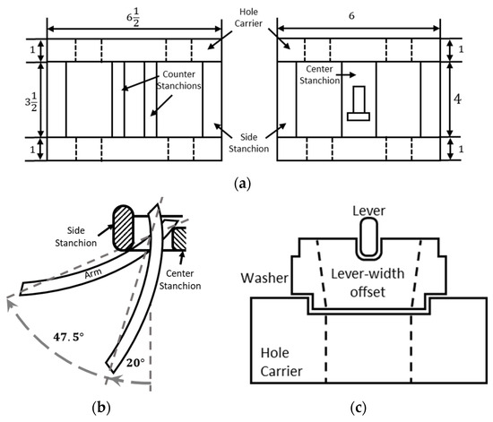
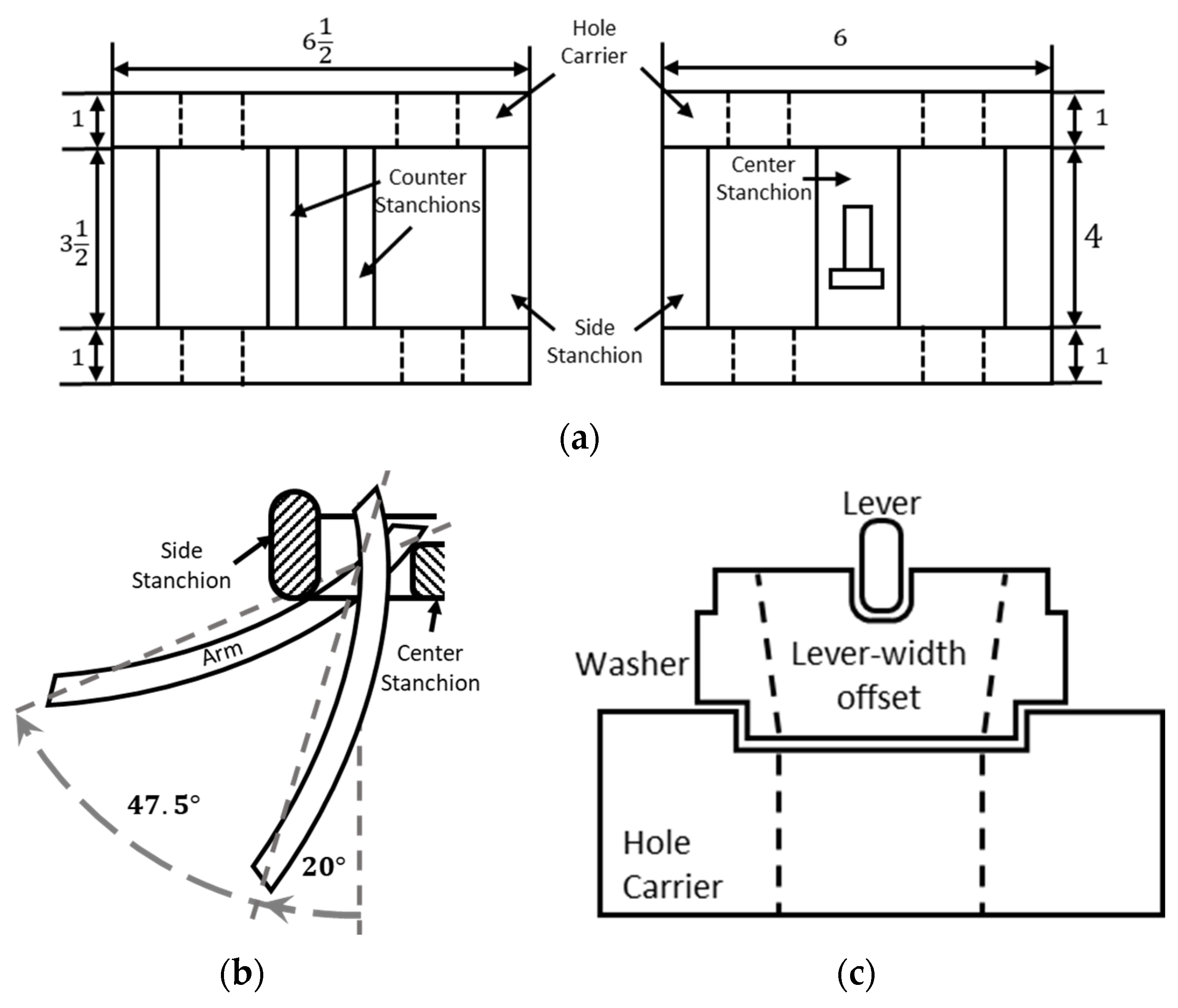
Catapult designs evolved over hundreds of years, influencing the dimensional ratios proposed by ancient engineers. Philon suggested wider hole carriers, whereas Vitruvius recommended longer stanchions resulting in extended spring lengths, as shown in Figure 2a. Although these variations may appear minor, they affect the energy storage capacity of the torsion springs. For example, the transition from straight to curved rotating arms in Scorpio catapults increased the allowable arm rotation, thereby enhancing the energy released to the projectile and the resulting impact velocity, shown in Figure 2b. Modifications in the stanchion positioning and geometry were introduced to further increase the arm rotation. The Scorpio catapult was one of the most advanced torsion artillery devices during Silla’s siege. Another suggested design feature of the Vitruvius’ Scorpio is the oblong-shaped washer geometry to accommodate the space occupied by the holding levers as shown in Figure 2c. This modification increased the effective material volume within the spring bundle, thereby enhancing its energy storage capacity.
Figure 2.
Vitruvius’ catapult design features: (a) spring frame dimension ratios according to Heron and Philon on the left and ratios according to Vitruvius guidelines on the right [8]; (b) curved arm of Scorpio and the allowable angle of rotation; (c) Vitruvius’ suggested washer geometry [6].
Sources consistently mention human hair, horse hair and animal sinew as the primary constituents. While the application of oils or fats to protect the ropes from moisture degradation is frequently described [15], such treatments are generally assumed to have a negligible influence on mechanical strength but could affect the friction forces between rope surfaces. Although recorded instances exist of human hair being used during wartime, several authors have emphasized animal sinew as the preferred material because of its superior mechanical performance [6,8,15]. A detailed account of rope preparation suggests that the rope initially had a diameter of D/6 and was subsequently stretched during assembly, reducing the effective diameter by approximately one-third to D/9 [8,10].
2.2. Rope Material Properties
Although ancient sources consistently mention human hair, horse hair and animal sinew as materials for torsion spring ropes, their mechanical properties differ and will influence the amount of stored elastic potential energy in the spring. Therefore, a quantitative comparison of these materials is essential to evaluate the performance of ancient artillery.
Tensile tests conducted by Kunchi et al. reported Young’s modulus values ranging from 3.0 to 6.0 GPa [16], while yielding occurs between 2.6 and 4.4% strain corresponding to yield stresses of 82–126 MPa. The post-yield strain-hardening region leading to failure stresses was found to be between 161 and 231 MPa and strains of 32–49%. Hu et al. measured Poisson’s ratio using advanced optical techniques and reported values between 0.36 and 0.39, with a mean value of 0.377 [17].
Bolormaa et al. conducted experimental studies on Mongolian horse tail hair and reported initial Young’s modulus values ranging from approximately 2.55 to 4.88 GPa. They also reported an ultimate tensile strength ranging between approximately 175 and 252 MPa with failure strains of 43–52% [18]. Kania et al. also reported young’s modulus values of 1.5–2.5 GPa and yield stresses between approximately 80 and 110 MPa [19]. To date, no direct measurements of the Poisson’s ratio for horse hair have been reported, largely due to the experimental challenges associated with measuring the transverse strain in micro-scale fibers. In the absence of direct data, a Poisson’s ratio similar to that of human hair (ν ≈ 0.38) was adopted in this study.
Historical texts do not specify the exact anatomical source other than excluding pig tendons. In general, sinew refers to fibers taken from the shoulders or feet of animals, where high elastic energy storage “springy” is required [15]. In this study, equine tendons were considered because of their function as specialized energy-storing tissues. The stress–strain response is characterized by an initial toe region generally up to 3–4% of the initial strain, followed by a near-linear elastic region from 4 to 11% with an elastic modulus ranging between 1097 and 2500 MPa. The yield strain was reported in the range of 5–13%, corresponding to yield stresses between 48 and 52 MPa. The ultimate tensile stress typically falls between 65 and 120 MPa, with failure strains ranging from 10 to 25% [20]. Another study by Burgio et al. summarizing the mechanical properties of horse tendons (SDFT) reported a Young’s modulus ranging between 970 and 1220 MPa, UTS ranging between 65 and 130 MPa and their respective failure strains between 12.5 and 26%, similar to the values mentioned earlier [21]. Vergari et al. employed real-time laser scanning to measure cross-sectional deformation during tensile loading of the SDFTs and reported an average Poisson’s ratio of 0.55 ± 0.12 [22].
2.3. Modeling Considerations
A study conducted by Paasch introduced a formulation that accounts for non-axisymmetric cross-sections using a generalized torsion constant rather than the polar moment of inertia [10]. However, several assumptions in this approach are inconsistent with the historical descriptions. For instance, the slit formed by the rotating arm was assumed to occupy one-fifth of the spring diameter, which is much smaller than the Vitruvian design guidelines. Additionally, the model assumes a solid spring bundle neglecting inter-rope sliding effects that significantly reduce the effective shear resistance. Nevertheless, Paasch considered a rope packing efficiency of 72% and the effect of pre-stress [10].
Rossi in his work modeled the torsion spring as a bundle of elongated individual ropes rather than a purely torsional element [11]. Although this approach incorporates engine dynamics, it neglects the effects of packing efficiency. Furthermore, if the initial conditions of the pre-stressed ropes are considered, it would limit the allowable arm rotation, potentially limiting the allowable arm rotation. Rossi also referenced nano-scale tensile studies of human hair to define material properties [11]. However, such data may not be directly applicable to the mechanical behavior of macroscopic fibers [23]. Despite these limitations, the methodologies proposed by Paasch and Rossi provide an essential foundation for further investigation.
Another work done by Paasch et al. [24] combined the two bundle diameter formulas together, with the hypothesis that both formulas can provide the optimum diameter for the arrow shooter. This approach was used to determine the relationship between the mass and length of the arrow by assuming a virtual density of the tip to attain a reasonable geometry of the tip. However, the mass–diameter relation corresponds to Palintone machines whereas the arrow length–diameter relationship is specific to Euthytone designs. Because the two catapult types follow different dimensional ratios (refer to Table A1 and Table A2 in Appendix A) and consequently have different energy storage capacities, equating these formulations will lead to invalid conclusions.
3. Materials and Methods
3.1. Arrow and Aerodynamic Analysis
3.1.1. Input Parameters
The arrow analyzed in this study was characterized by the following geometric and material parameters.
- Total mass: kg;
- Tip geometry: Square pyramid with base 30 mm × 30 mm and height 40 mm;
- Shaft length: m [6].
These were based on previously reported measurements and finite element analysis results [12,13].
The ballistic constraints were set for the arrow to reach a required horizontal impact velocity of m/s after traversing a horizontal distance of m [13].
3.1.2. Physical Properties
The remaining material and aerodynamic properties were sourced from obtained published references. The density of iron, representative of wrought and low-carbon iron, was considered to be 7800 kg/m3 [25]. For hardwood suitable for shaft manufacture, a density of 640 kg/m3 was used [26]. The aerodynamic drag coefficients for arrow- and bolt-like projectiles were derived from experimental studies, which reported values ranging from 1.5 to 3.0, depending on the Reynolds number and tip geometry [27,28]. These input parameters are summarized in Table 1.
Table 1.
Arrow and aerodynamics input parameters.
3.1.3. Geometry and Mass Distribution
The arrow tip was modeled as a solid square pyramid, and the shaft as a solid circular cylinder, listed in Table 2.
Table 2.
Mass distribution summary.
Using the adopted material densities, the computed shaft diameter was approximately 15.95 mm, which is consistent with the archeological reconstruction of the Roman artillery bolts.
3.1.4. Aerodynamic Model
A comprehensive aerodynamic modeling approach was evaluated to estimate the drag coefficient. It is based on clear physical justifications, assumptions, and implications for trajectory analysis.
Composite-Area Decomposition Model (Non-Standard Reference Area)
This approach decomposes the arrow into aerodynamic components (tip and shaft) with individual drag coefficients and then combines them using area-weighted averaging [29,30].
Based on the aerodynamic literature for similar shapes, the drag coefficients for each component are as follows [31]:
- (a square pyramid nose with a half-angle to the corner of , intermediate between cone and blunt plate, with a height-to-width ratio of 1.33 that can be categorized as bluff and not streamlined) [32,33,34].
- (cylindrical body, considering axial skin-friction drag via turbulent flat-plate correlation, with a reference velocity of ) [35,36].
Area-Weighted Combination Formula:
where the reference area is chosen as the tip-base area.
This yields:
The Composite-Area Decomposition Model provides a detailed component-level analysis, explicitly accounting for the contributions of the tip and shaft while enabling a sensitivity analysis of individual components, making it methodologically rigorous. However, it uses a non-standard reference area (tip base area of 9.00 cm2 instead of the shaft’s maximum cross-section of 2 cm2), which is unconventional in projectile aerodynamics.
It is important to note that the equivalent drag coefficient is influenced by the chosen frontal area. As long as the drag coefficient for each component is selected with sound justification, it can be accurately used to calculate the drag force for any specified reference frontal area.
The Reynolds number for this problem should be defined to select an appropriate drag force law. Assuming an average traveling velocity of 20 m/s as a realistic estimation, the Reynolds number can be calculated as follows:
where is the shaft diameter and is the dynamic viscosity of air.
In this turbulent regime (), the drag force is proportional to [37]. Therefore, the standard quadratic drag force law is an appropriate choice for this study’s purpose.
where the reference area was considered the frontal area of the pyramid base.
The arrow motion is governed by Newton’s second law in two dimensions, with gravity and drag included.
where:
is the total velocity magnitude;
m/s2 is gravitational acceleration.
The nonlinear ODE system was solved numerically using the 4th-Order Runge–Kutta (RK4) method [38], which provides excellent accuracy for this type of problem. The following assumptions were made to implement this solution method:
- Time step: (ensures convergence and accuracy);
- Initial conditions: ;
- The integration continued until ground impact. ;
- Maximum integration time: 50 s (conservative upper bound).
As explained previously, the goal was to find the launch velocity and launch angle (φ) that satisfy the ballistic constraints including a range of m and horizontal impact velocity of m/s.
The problem was approached as an optimization problem with the following description.
Subject to: (ground impact condition), where is the impact time when y = 0, the following strategy was considered.
- Grid search over with 1° increments;
- For each angle, grid search over m/s with 0.5 m/s increments;
- Identify candidate solutions with ;
- Refine best candidates using Nelder–Mead optimization [39];
- Select solution with lowest objective function value.
Given the launch conditions, the kinetic energy required to launch the arrow can be calculated as follows:
The ODE solution and calculated results considering the selected drag coefficient, resulting launch conditions, and corresponding required kinetic energies are reported in the Section 4.
Although the initial analysis considered an impact velocity with a horizontal component of 6 m/s, this low speed implies an extended flight time to cover the 100 m distance. During this prolonged flight, the gravitational force acting on the arrow causes a notable drop in altitude and a significant reduction in the vertical component of the arrow’s speed upon impact. This results in a steep impact angle against the wall, resembling a nose-diving condition. To evaluate a more realistic scenario, a case study was conducted with a launch velocity of 50 m/s and varying launch angles, with the findings briefly summarized below and further detailed in Appendix C.
3.2. Torsion Spring Mechanics Model
3.2.1. Potential Energy Storage Capacity of Torsion Spring
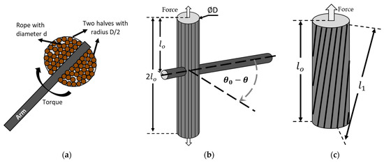
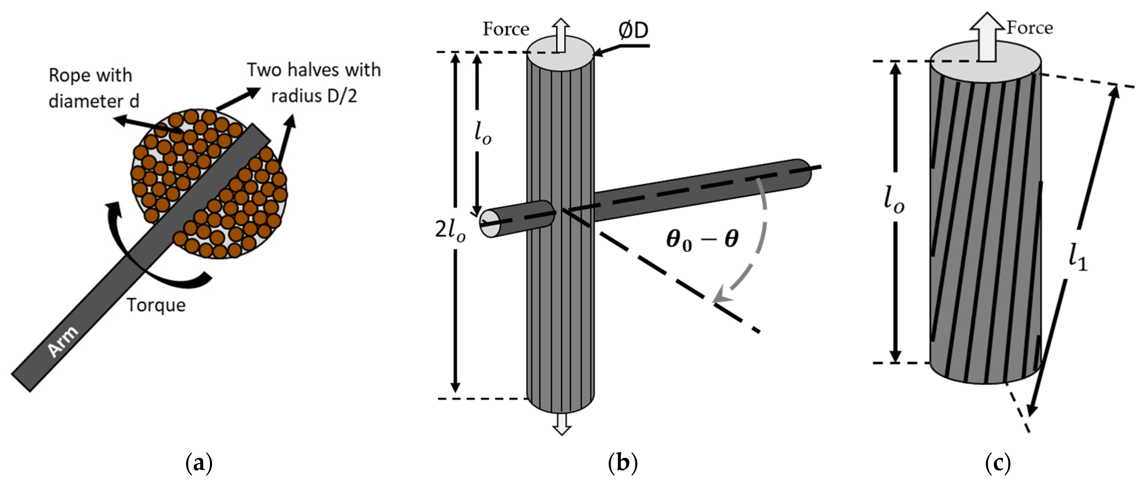
As discussed in the literature, modeling a spring bundle as a cylinder under pure torsion is an oversimplification. Therefore, the present study adopts the analytical framework proposed by C. Rossi, which is based on linear axial strain induced in individual ropes due to arm rotation. Although the bundle cross-section at the mid-length is not perfectly circular, as shown in Figure 3a, a circular approximation is adopted.
Figure 3.
(a) Actual spring bundle twisting; (b) assumed spring loading by twisting of arm; and (c) axial force due to rope elongation from arm rotation.
The spring bundle was assumed to be locked at both washer ends with torque applied in the middle. As illustrated in Figure 3b,c, the force and energy calculations can be performed for half of the spring bundle. An additional packing efficiency factor η is introduced to account for the voids between discrete ropes within the bundle. While = 0.72 is assumed in the literature [10], considering the Vitruvian washer design and diameter of the rope mentioned earlier, = 0.85 is considered, since the maximum packing efficiency of circles in an infinite plane is 90.69% [40]. This assumes that η is independent of the radial position.
The axial force can be estimated as follows:
By incorporating the efficiency factor, the elastic potential energy stored in both springs owing to the axial force can be expressed as:
When determining the maximum allowable twist angle, packing efficiency is not required because the failure limit in the extreme radial fiber is considered. The maximum twist angle is given by:
3.2.2. Velocity Estimation
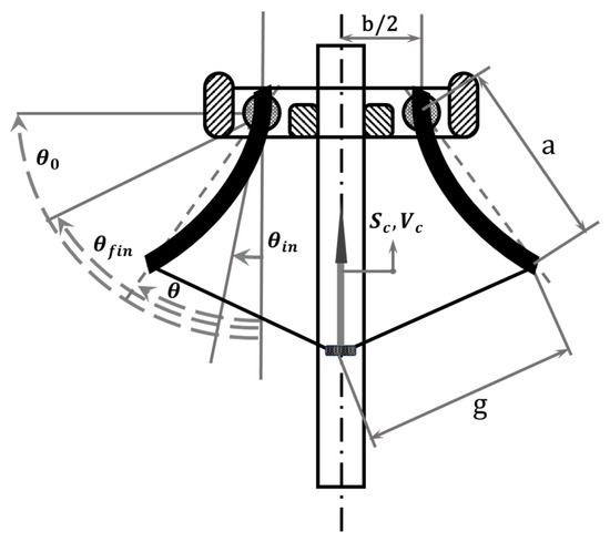
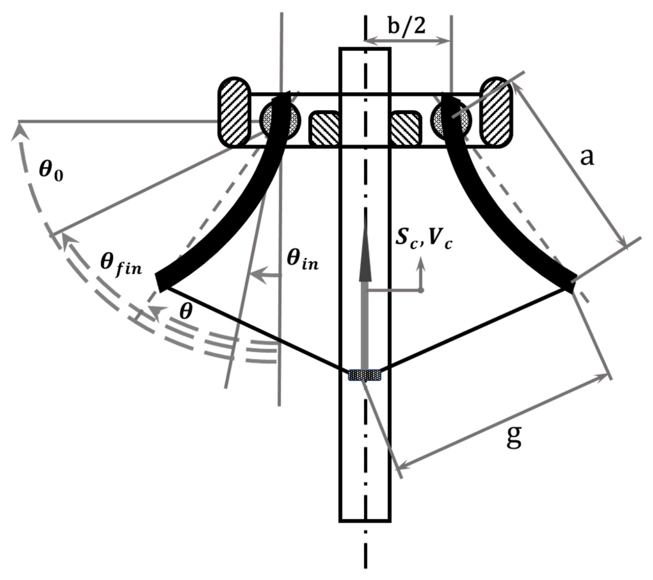
Figure 4 represents a schematic diagram of the torsion catapult, highlighting different angular positions of the arms. As shown, the projectile displacement along the slider is governed by the angular position of the catapult arms. The linear displacement and velocity of the projectile are calculated as follows, using the catapult geometric dimensions listed in Table 3.
Figure 4.
Schematic diagram of catapult with displacement and velocity of projectile caused by arm rotation. The corresponding geometric dimensions are listed in Table 3.
Table 3.
Geometric features and their dimensional ratios.
The final velocity of the projectile can also be expressed by enforcing energy balance between the stored elastic energy, frictional losses, inertial energy and projectile kinetic energy, as follows:
where ; ; (refer to Appendix B.1 for the derivation) is the mass moment of inertia of the rotating arm about its axis, m is the mass of the projectile (arrow), and f is the coefficient of friction between the projectile and the slider (Figure 4). The velocity expression is an explicit function of arm rotation angle θ. Therefore, the final release velocity of the projectile is obtained by evaluating the equation at the terminal rotation angle, i.e., .
3.2.3. Material Properties and Component Dimensions
As detailed in Section 2.2, the mechanical properties of the proposed materials vary across experimental studies. To reduce uncertainty either a mean value is assumed, or calculated, or the values of a test case are considered. For female hair properties, values corresponding to a 26 years old female sample were considered [16]. For horse hair, a mean initial elastic modulus of 3.9 MPa was selected, and the property set of the corresponding test sample was considered [18]. For sinew, selecting a representative parameter set directly from the reported experimental results was not straightforward; therefore, a rationalized set of assumed values was defined. Tendon exhibits nonlinear material response with a toe region in the beginning and was neglected under the assumption that the rope bundle was pre-stretched prior to operation. The toe region was assumed to extend up to 4% strain, followed by a linear elastic regime up to 5% additional strain resulting in a yield at approximately 9% total strain. A yield stress of 50 MPa was considered, resulting in a Young’s modulus of 1000 MPa for the linear region, consistent with the reported experimental ranges. The ultimate tensile strength values ranged from 65 to 128 MPa, with the majority clustering near 110 MPa. Therefore, a representative mean value of 115 MPa was adopted for this analysis [21].
The material properties mentioned above in Table 4 cannot be implemented directly because the composition of the rope and geometry of how the yarn is coiled into a rope should be considered. The formula for rope stiffness with packing efficiency can be written as:
where is volume fraction of a constituent material, is the stiffness modulus of the material, and is a helix angle of the rope’s fibers [41]. For the hair rope considered by Rossi, he assumed a factor of 0.8 to estimate the property of rope [11]. Four different cases of ropes were considered: ropes composed of human hair, horse hair, sinew and a composite rope consisting of equal proportions of all three materials, shown in Table 5. For the composite configuration, both yield stress and allowable strain limits were carefully considered because rope yielding is governed by the weakest constituent material. In this case, the lowest permissible strain among the individual materials was adopted as the governing limit. Hooke’s law was used to estimate the strain threshold leading to yield stress, based on the assumption of linear elastic behavior because exceeding this value would initiate yielding in the weakest constituent and result in partial yielding of the composite rope (see Appendix B.2 for further details).
Table 4.
Mechanical properties of female hair, horse hair and sinew.
Table 5.
Mechanical properties of ropes made of hair, horse hair and sinew.
Since the study focuses on the Scorpio catapult used for shooting arrows of length S = 481 mm, Vitruvian dimensional ratios were adopted. The key geometric features for the analytical calculations are shown in Figure 4 and their dimensional ratios are listed in Table 3.
The torsion spring mechanics model presented above was used to evaluate the elastic energy storage and the resulting arm-driven acceleration of the projectile. The effects of material properties and geometric parameters on stored energy and release behavior are examined and the corresponding release velocities for different rope materials are discussed in Section 4.
4. Results
4.1. Aerodynamic Drag
To represent the results of the launch condition optimization, the drag coefficient, drag parameter, and reference area for each scenario are reported again in Table 6.
Table 6.
Drag Model parameters summary.
By solving the optimization problem to determine the launch conditions for minimum launch velocity, free launch angle and free impact height were obtained, as shown in Table 7:
Table 7.
Launch and impact velocity and projectile angle for different scenarios of impact.
All three scenarios lead to either a physically unfeasible launch condition or an extreme impact condition. In summary, each scenario imposes a constraint that, when combined with and , results in either a very high required launch velocity or angle or a steep impact with a significant drop-off at the point of impact. However, it is important to note that achieving impact at the same height necessitates a reasonable launch velocity at a high launch angle. Consequently, the authors reevaluated the imposed constraints and instead assessed impact conditions with a fixed launch velocity of 50 m/s and a launch angle ranging from 10° to 70°. As will be demonstrated below, various potential candidate materials for the torsion spring can achieve this launch velocity. Assuming the impact velocity is comparable to or exceeds the initial target of 6 m/s, it is reasonable to conclude that the machine can successfully shoot the described arrows at a similar target from the specified distance.
Table below contains the calculated impact conditions for each scenario, the kinetic energy requirements can be calculated as shown in Table 8:
Table 8.
Impact conditions with varying launch angles ().
The recommended kinetic energy for the elastic storage system design is KE ≈ 187.5 J. If we account for:
- Mechanical efficiency losses (10–20%) in the torsion springs;
- Friction in the release mechanism (5–10%);
- Arrow orientation and initial rotation energy.
A conservative design target of – J is recommended to accommodate these losses [8,42].
The energy lost to the aerodynamic drag during the 100 m trajectory is:
where is the initial kinetic energy, is the final kinetic energy, and is the final potential energy (≈0 at ground impact).
The energy components for each scenario are listed in Table 9.
Table 9.
Energy dissipation analysis.
As can be seen from the results reported in Table 9, the higher launch angle results in a lower drag loss. However, all three cases demonstrate a comparable order of magnitude for the energy lost to the resisting drag force.
The considered launch velocity of 50 m/s and the calculated launch velocity of 71 m/s for impact at both fall within the archeological and experimental reconstructions from Vindolanda and Hatra, where Roman artillery arrows and bolts are reported to achieve launch velocities in the range of 30–60 m/s [42,43]. This agreement further validates the ballistic modeling approach and confirms that the hybrid estimate is physically and historically accurate.
4.2. Elastic Potential Energy and Projectile Velocity
The Scorpio catapult is designed to operate with a maximum arm rotation of . The material limiting the maximum allowable rotation was independently evaluated using Equation (18), as shown in Table 10. The results indicate that all the rope configurations considered in this study have allowable rotations exceeding , confirming that the designed operating rotation can be achieved without inducing material yielding.
Table 10.
Maximum allowable rotation constrained by elastic behavior.
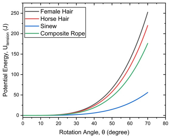
The simplest case of linear elastic energy release resulting from rope elongation induced by twisting is considered. As shown in Figure 5, the ropes fabricated from human hair exhibited the highest energy storage capacity, reaching a maximum of 252.51 J. This was followed by horsehair ropes at 219.96 J and composite ropes at 176.20 J. In contrast, the sinew ropes displayed comparatively limited energy storage of 56.11 J. This reduced capacity can be attributed to the lower elastic modulus and the assumed linear behavior of the sinew near the toe region of the stress–strain curve.
Figure 5.
Elastic potential energy stored in the spring as a function of arm rotation angle.
However, elastic potential energy alone cannot fully characterize projectile performance as energy losses and inertial effects must also be accounted for to obtain a reliable estimate of the projectile velocity. A notable observation from Figure 5 is the amount of stored energy released during the arm rotation. For example, in the case of female hair ropes, the stored energy decreased from 252.51 to 2.73 J leaving approximately 1.1% of the initial value when the arm impacted the central stanchion and was brought to rest. A similar trend was observed for the other materials: the energy decreased from 219.96 to 2.38 J for horse hair, from 56.11 to 0.55 J for sinew and from 176.20 to 1.90 J for the composite rope.
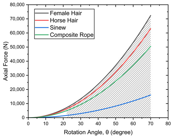
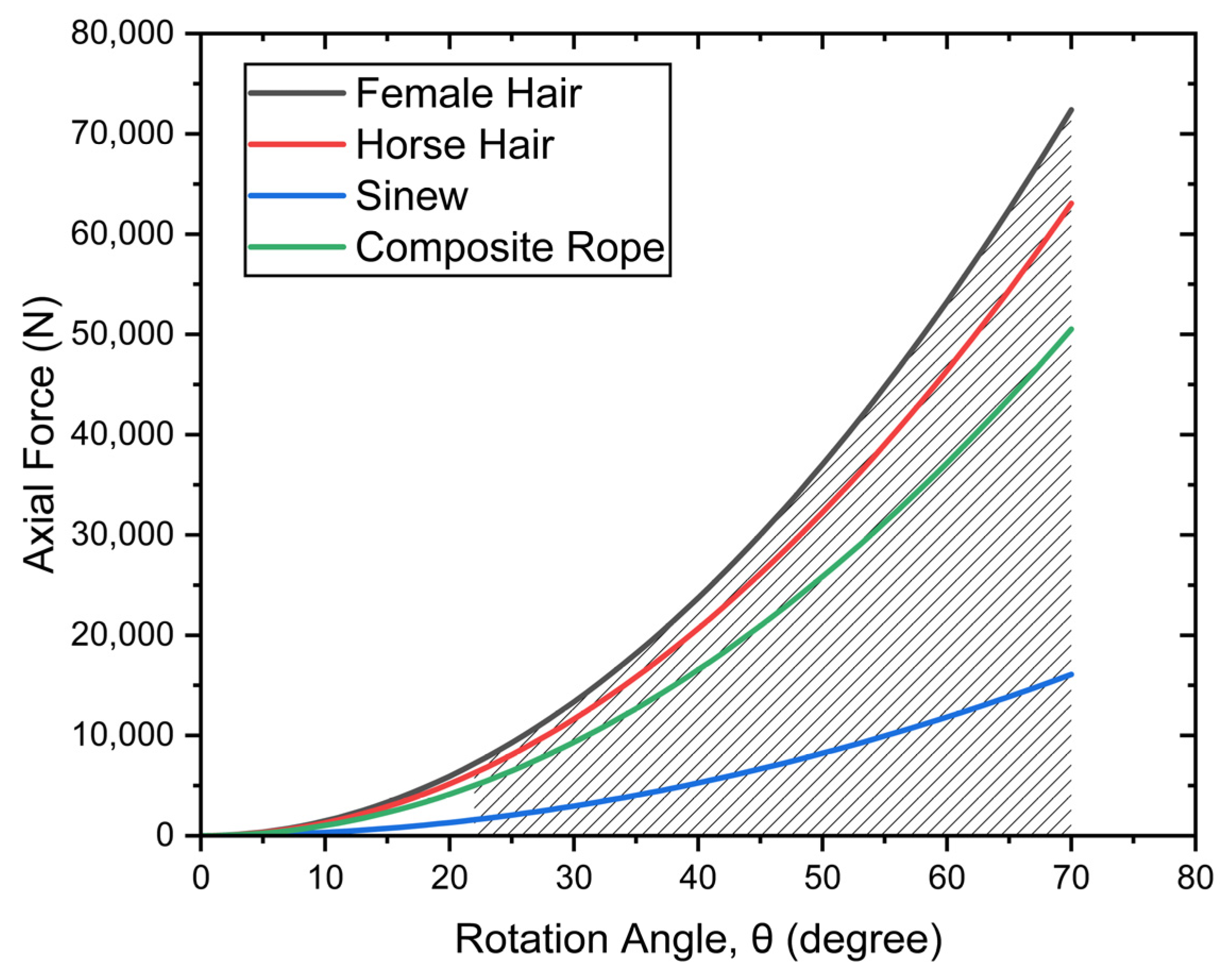
Figure 6 illustrates the material response as the bundle is deformed. Although energy is stored throughout the full range from 0° to 70°, only the portion from 70° down to 22.5° is released to drive the projectile forward, highlighted with the shaded area. This behavior aligns with what is commonly reported in the literature [15], where only a selected segment of the material response curve contributes to accelerating the projectile.
Figure 6.
Axial force as a function of arm rotation angle.
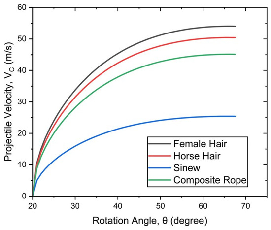
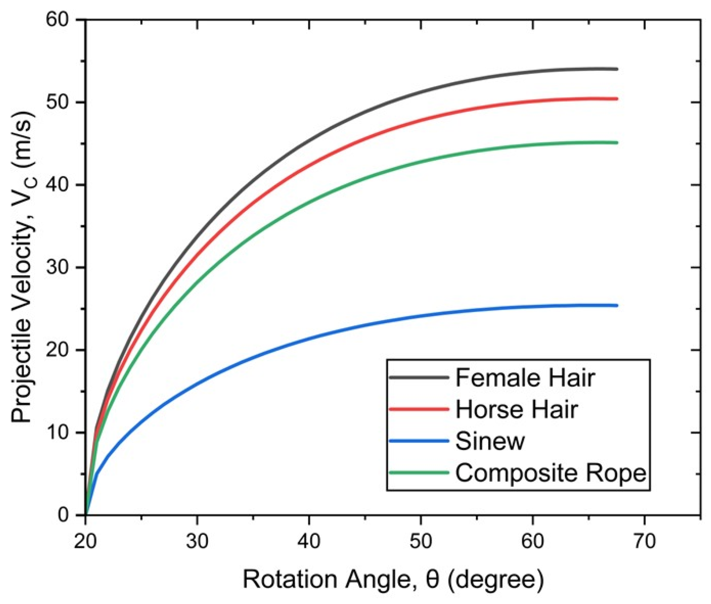
When the projectile is released from the catapult, the rope bundle is rotated to the designed angular position of . At , arrow velocity is zero and when released, the arm rotates from to , increasing the velocity of the projectile, as demonstrated in Figure 7. Consistent with the energy storage trends, ropes made from female hair yielded the highest final release velocity of 54.02 m/s, followed closely by horse hair and composite ropes with final velocities of 50.41 m/s and 45.11 m/s, respectively. Due to its lower stored energy, sinew produces a comparatively lower release velocity of approximately 25.40 m/s. Notably, the maximum release velocity does not occur exactly at but rather at 1.5° prior to the final angular position with a marginally higher velocity. It is important to note that the previously assumed launch velocity of 50 m/s falls within the capabilities of the most promising candidates for the rope material.
Figure 7.
Dardo release velocity generated by different rope materials.
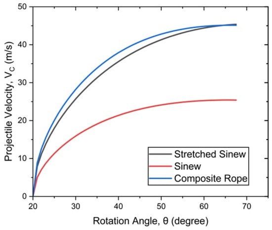
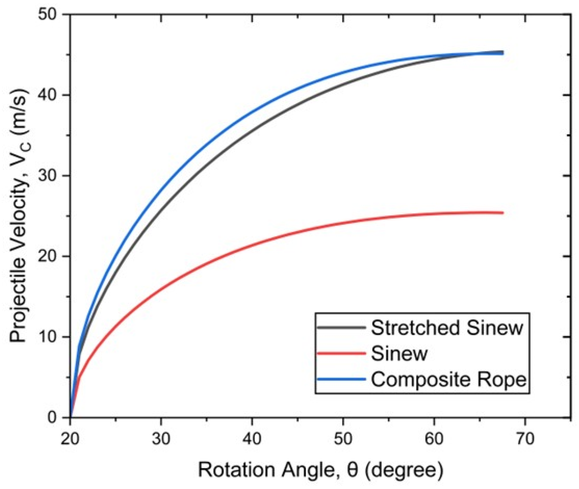
Although sinew ropes exhibited the lowest performance in the baseline configuration, they were not utilized to their full strain capacity under the assumed conditions. In a special case, in addition to the initial 4% pre-strain (toe region), an additional 45° of allowable rotation is applied using levers as pre-strain leaving only 74.23° of the total 119.23° allowable rotation for energy release. Under this configuration, the performance of the sinew becomes comparable to that of the composite rope discussed earlier, as illustrated in Figure 8. While the composite rope maintains superior performance throughout most of the rotation range, it reaches its peak prior to the final position, whereas the pre-stretched sinew rope exhibits slightly lower velocities during rotation but surpasses the composite rope at the final angular position. However, the pre-strain discussed arose solely from the prescribed initial twist and not from an imposed uniform elongation of the ropes as prestress. So, the resulting stresses and stored energy of ropes near the bundle axis were still below the levels attainable when a consistent pre-stress is applied to each rope. This performance advantage further increases with higher levels of prestress. Moreover, in the larger strain range, sinew exhibits near-linear elastic behavior which further supports the feasibility of sinew as a viable material for spring rope fabrication.
Figure 8.
Comparison of performance of stretched sinew, sinew and composite ropes.
5. Discussion
The results highlight several important insights into the mechanics and performance of the Roman torsion artillery. First, the study demonstrates that the reconstructed arrow geometries and ballistic trajectories are consistent with the historically reported performance of Roman arrow-shooting engines which typically produced projectile release velocities between 30 and 60 m/s. By comparing the required initial velocities under varying aerodynamic drag coefficients, it is evident that drag plays a dominant role in long-range projectile attenuation. Even modest changes in the drag coefficient produce significant shifts in the required release velocity, illustrating the sensitivity of ancient artillery performance to projectile shape, surface roughness, and construction precision. Furthermore, the proposed composite approach allows for the following standard aerodynamic conventions while employing a rigorous component decomposition methodology. This approach produces drag coefficients that agree with the ballistics literature and launch parameters that are consistent with historical evidence.
The evaluation of historically attested rope materials reveals a nuanced history. Human and horse hair, both possessing high elastic moduli and favorable yield strains, have the greatest energy storage capacity and correspondingly highest release velocities. These findings align with several classical descriptions praising the mechanical suitability of animal hair ropes. Sinew, which has been historically favored, exhibits lower stiffness and a nonlinear initial toe region limiting its energy storage capacity unless the ropes are pre-stretched. When the sinew rope is pre-strained beyond this region, its available elastic energy and release performance increase substantially, approaching those of hair-based bundles.
The analytical approach used here is based on the axial strain in individual fibers rather than a simplified torsional cylinder model and is consistent with ancient descriptions of rope behavior. This method captures the loading mechanisms and predicts the maximum allowable twist, which exceeds the required 70° rotation for all rope types. This finding supports the feasibility of the historically documented Scorpio geometry and validates the Vitruvian dimensional ratios in terms of functional performance.
Finally, the integration of archeological measurements from Pompeii’s fortified walls with mechanical modeling provides a rare empirical anchor for evaluating ancient weapon performance. By coupling measured crater-based impact velocities with reconstructed launch conditions, this study bridges archeology, classical texts and modern mechanics.
6. Conclusions
This study provides an integrated analytical reconstruction of Roman Scorpio catapult performance by combining archeological impact evidence with a mechanics-based evaluation of ancient torsion-spring materials. In contrast to earlier reconstructions based on empirical or mechanically simplified relationships between projectile mass, velocity, and wall deformation, the present approach explicitly incorporates dynamic analysis based on calibrated material behavior of the wall and in-flight aerodynamic effects. This integrated framework establishes a physically constrained link between launch conditions, flight dynamics, and impact response.
The derived release velocities required to reproduce the impact conditions observed on the Pompeii city walls fall within historically plausible ranges, reinforcing the validity of the reconstructed weapon geometry and modeling assumptions. Evaluation of candidate torsion-spring materials indicates that ropes made from human and horse hair exhibit the highest elastic energy storage capacity, while sinew provides adequate performance only when operated under significant pre-strain, consistent with historical descriptions of rope-bundle preparation. All examined materials demonstrate allowable twist angles exceeding the operational requirements, confirming that the reconstructed Scorpio design is mechanically feasible. Overall, the results support the effectiveness of Roman Scorpio artillery and illustrate the value of integrating ballistic aerodynamics with calibrated material modeling for the reconstruction of ancient war machines.
Author Contributions
M.M.T.: conceptualization, analytical modeling, data curation, and writing—review and editing. A.A.L.: conceptualization, analytical modeling, supervision, data curation, and writing—review and editing. M.G.: writing—review and editing, supervision, resources, and funding acquisition. All authors have read and agreed to the published version of the manuscript.
Funding
This research was supported by the project “SCORPiò-NIDI”, CUP D53D2301472 0006, funded by the Italian Ministry of Research under the PRIN (DD n.104/2022) funding initiative.
Institutional Review Board Statement
Not applicable.
Informed Consent Statement
Not applicable.
Data Availability Statement
Research data are available upon request.
Acknowledgments
The author would like to thank Gabriel Zuchtriegel, Director of the Archeological Area of Pompeii, Giuseppe Scarpati, Head of the Study and Research Area, and Valeria Amoretti. The research activities are part of the MUR—PRIN 2022 project “SCORPiò-NIDI”.
Conflicts of Interest
The authors declare no conflicts of interest. The funders had no role in the design of the study; in the collection, analyses, or interpretation of data; in the writing of the manuscript; or in the decision to publish the results.
Nomenclature
| Symbol | Description |
| D | Spring bundle diameter |
| L | Length of spring bundle |
| R | Radius of spring bundle |
| S | Arrow length |
| m | Projectile mass |
| Volume of the arrow tip | |
| h | Arrow tip height |
| Arrow tip base | |
| Total mass of arrow | |
| Mass of arrow tip | |
| Mass of arrow shaft | |
| Density of iron | |
| Mass of the arrow shaft | |
| Wood density | |
| Diameter of arrow shaft | |
| Reference area of arrow | |
| Frontal area of the shaft | |
| Frontal area of the tip | |
| Density of air | |
| k | Drag parameter |
| Drag force | |
| Equivalent Drag Coefficient of the whole arrow | |
| Component of the drag coefficient from the shaft | |
| Component of the drag coefficient from the tip | |
| Axial skin-friction drag coefficient | |
| Re | Reynold’s number |
| Dynamic Viscosity | |
| v | Velocity magnitude |
| x | Displacement in x direction |
| y | Displacement in y direction |
| Velocity component of arrow in x direction | |
| Velocity component of arrow in y direction | |
| φ | Launch angle |
| Gravitational acceleration | |
| Fi | Force acting on ith rope in the bundle |
| Ai | Ring area containing ith rope |
| Change in length of ith rope | |
| Packing efficiency of spring bundle | |
| Radial distance of ith rope from bundle axis | |
| R | Radius of spring bund |
| Energy storage in bundle due to tension | |
| θ | Angular position of arm |
| θmax | Maximum allowable rotation |
| σe | Equivalent yield stress of rope |
| E | Young’s Modulus of rope |
| Displacement of projectile on the catapult | |
| Wetted area of the shaft | |
| Velocity of projectile on the catapult | |
| a | Arm length |
| b | Half distance between two springs |
| g | Half-length of bow string |
| f | Coefficient of friction |
| μ | Dimensionless ratio of catapult geometry, g/a |
| ε | Dimensionless ratio of catapult geometry, |
| Curvature of arm | |
| a1 | Bigger diameter of arm |
| a2 | Smaller diameter of arm |
| Mass moment of Inertia of arm | |
| Reference orientation of spring | |
| Final resting angular position of arm | |
| Angular position of arm when fully loaded | |
| Cross-sectional area of spring | |
| Cross-sectional area of rope | |
| d | Rope diameter |
| Packing density of rope | |
| β | Helix angle |
| Fraction of ith material in the rope | |
| Elastic Modulus of ith material in the rope | |
| Initial Kinetic energy | |
| Final Kinetic energy | |
| Initial Potential energy | |
| Initial/Release velocity | |
| Dissipated energy due to drag |
Appendix A
Table A1.
Dimensions for Euthyone, arrow-shooting catapults proposed by Vitruvius [8].
Table A2.
Dimensions for Palintone, stone-throwing catapults proposed by Vitruvius [8].
Table A1 and Table A2 represent dimensions of some of the similar components of arrow-shooting catapults and stone-throwing catapults, designed by Vitruvius. Although the data does not give a complete picture of different designs required for stones and bolts, it gives a basic understanding of geometric features being different leading to different energy storage capacities for same diameter D assumed.
Appendix B
Appendix B.1. Derivation of Moment of Inertia of Curved Arm with Axis of Rotation About the Thicker End
Figure A1.
Geometry of curved arm.
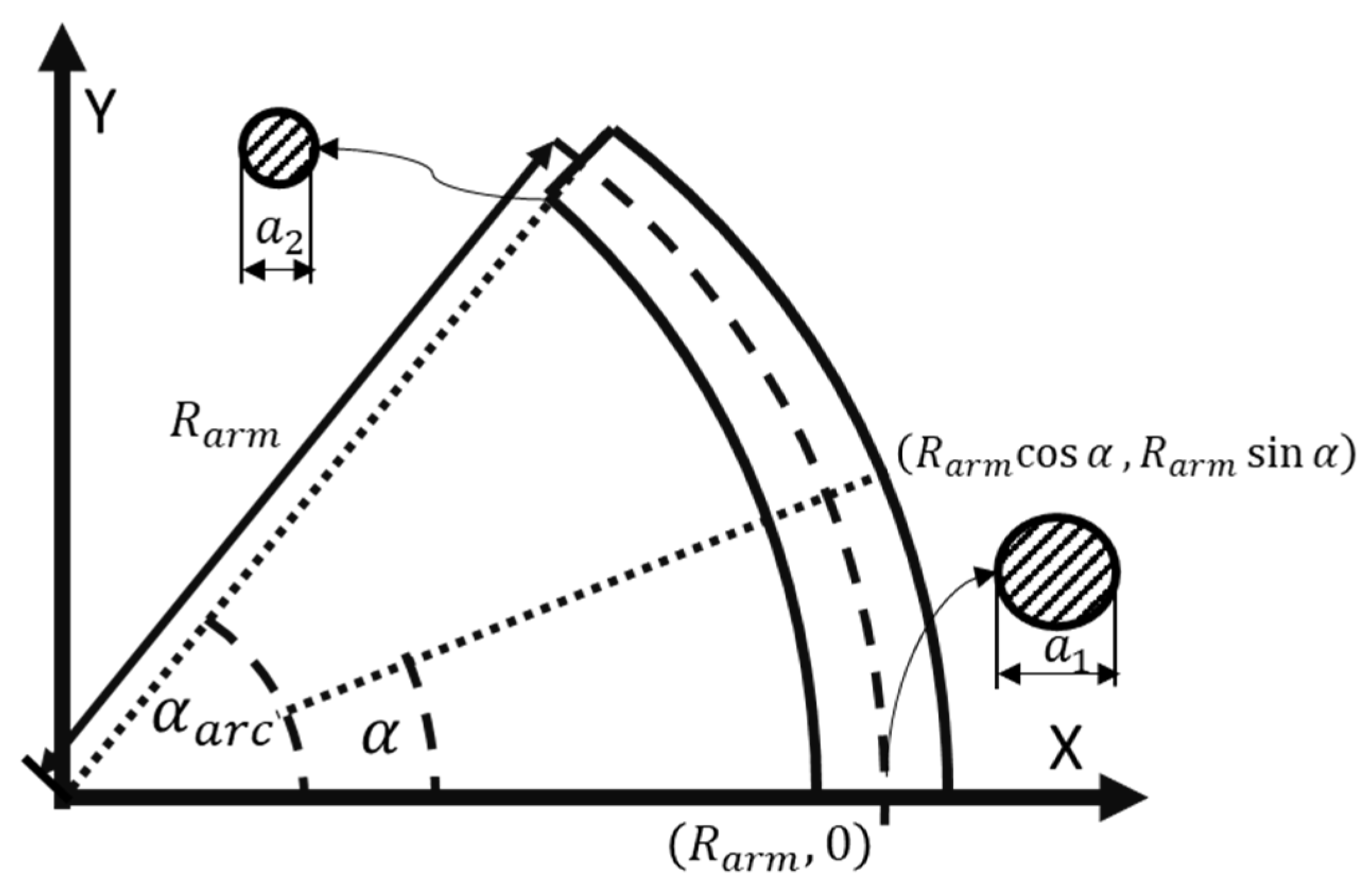
Angle subscribed by the arc:
Cross-section radius along the arc:
where and .
Cross-sectional area as a function of arc angle:
Mass variation along the arc:
Mass moment of inertia:
Here,
Final form:
Appendix B.2. Mechanical Behavior of Composite Rope
Figure A2.
Stress–Strain relation of different ropes considered.
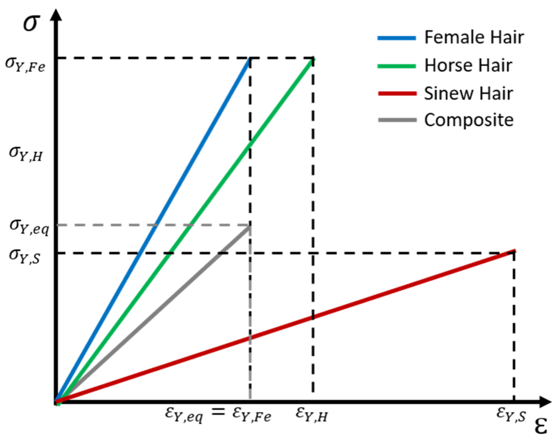
The minimum strain capacity among the materials was taken as the limiting value, because exceeding it would cause the weakest constituent to yield, initiating partial yielding within the composite rope.
Appendix C
Appendix C.1. Calculation of the Drag Coefficient for the Shaft
A long slender shaft aligned with the velocity has drag dominated by skin friction rather than bluff-body pressure drag. A standard turbulent smooth-surface correlation used in engineering texts is of the form:
This equation is derived from skin-friction coefficient for an external flow when turbulent boundary layer similarity theory is applied, assuming a fully turbulent boundary layer on a smooth flat plate with zero pressure gradient.
We can use the appropriate Reynolds equation and consider the equation for the friction drag:
And assume that the wet area is .
To convert that into an equivalent on :
This makes weakly velocity-dependent (through ). However, by considering 30 m/s as a reasonable reference velocity, can be calculated as follows:
Considering the kinematic viscosity of the air and a reference velocity of , and frontal area of the tip as the reference area , , can be calculated as follows:
Appendix C.2. Calculated Impact Conditions
Table A3 contains the impact conditions calculated for a launch velocity of 50 m/s and launch angle between 10 and 70, as well as the total flight time, , and the amount of drop-off from the launch point to the point of impact to a wall at 100 m with a launch velocity of 50 m/s, and a drag coefficient of 0.418.
Table A3.
Impact conditions for varying launch angles with a and Vlaunch = 50 at x = 100 m.
References
- Rossi, A. The Survey of the Ballistic Imprints for a Renewed Image of Unearthed Pompeii. Nexus Netw. J. 2024, 26, 307–324. [Google Scholar] [CrossRef] [Scilit]
- Maiuri, A. Studies and Research on the Fortification of Pompeii (Studi e Ricerche Sulla Fortificazione di Pompei); G. Bardi: Milano, Italy, 1930. (In Italian) [Google Scholar]
- Maiuri, A. Introduction to the Study of Pompeii. In Pompeian and Herculanean Antiquities (Introduzione allo Studio di Pompei. In Antichità Pompeiane ed Ercolanesi) 1942-43; Onorato, G.O., Ed.; G.U.F. “Mussolini”: Napoli, Italy, 1943. (In Italian) [Google Scholar]
- Rossi, A.; Gonizzi Barsanti, S.; Bertacchi, S. Use of Polybolos on the City Walls of Ancient Pompeii: Assessment on the Anthropic Cavities. Nexus Netw. J. 2025, 27, 243–272. [Google Scholar] [CrossRef] [Scilit]
- Diels, H.; Schramm, E.A. Philo’s Belopoiika; Fourth Book of Mechanics (Philons Belopoiika; viertes Buch der Mechanik); Verlag der Akademie der Wissenschaften: Berlin, Germany, 1919. (In German) [Google Scholar]
- Marsden, E.W. Greek and Roman Artillery: Technical Treatises; The Clarendon Press: Oxford, UK, 1971. [Google Scholar]
- MacDhnouill, G.; Nanzydon. A Modern Reconstruction of Vitruvius’ Scorpion. Available online: https://www.eg.bucknell.edu/~whutchis/scorpion/Scorpion%20Documentation.pdf (accessed on 2 March 2026).
- Marsden, E.W. Greek and Roman Artillery: Historical Development; The Clarendon Press: Oxford, UK, 1969. [Google Scholar]
- Wilkins, A. Roman Imperial Artillery: Outranging the Enemies of the Empire; Archaeopress: Oxfordshire, UK, 2024. [Google Scholar]
- Paasch, K.M. Analysis of the Design Criteria for Ancient Greek and Roman Catapults. In COMSOL Multiphysics Conference 2010 Paris; University of Southern Denmark: Odense, Denmark, 2010; pp. 1–6. [Google Scholar]
- Rossi, C. Ancient throwing machines: A method to calculate their performance. Mech. Mach. Theory. 2012, 51, 1–13. [Google Scholar] [CrossRef] [Scilit]
- Russo, F.; Rossi, A. Ancient Science: From Effects to Ballistics Parameters. Eng. Proc. 2025, 96, 2. [Google Scholar] [CrossRef] [Scilit]
- Thakkar, M.M.; Ardeshiri Lordejani, A.; Guagliano, M. Structural Integrity Assessment of Pompeii’s City Wall Under Roman Artillery Fire: A Finite Element Approach. Eng. Proc. 2025, 96, 7. [Google Scholar] [CrossRef] [Scilit]
- Fratino, M.; Palmero Iglesias, L.; Rossi, A. Re-Construction of the Small Xanten-Wardt Dart Launcher. Eng. Proc. 2025, 96, 9. [Google Scholar] [CrossRef] [Scilit]
- Landels, J.G. Engineering in the Ancient World; Constable: New York, NY, USA, 2000. [Google Scholar]
- Kunchi, C.; Venkateshan, K.; Reddy, N.; Adusumalli, R. Correlation between Mechanical and Thermal Properties of Human Hair. Int. J. Trichology 2018, 10, 204. [Google Scholar] [CrossRef] [Scilit] [PubMed]
- Hu, Z.; Li, G.; Xie, H.; Hua, T.; Chen, P.; Huang, F. Measurement of Young’s modulus and Poisson’s ratio of human hair using optical techniques. Proc. SPIE 2010, 7522, 773–781. [Google Scholar] [CrossRef] [Scilit]
- Bolormaa, B.; Drean, J.Y.; Enkhtuya, D. A study of the diameter distribution and tensile property of horse tail hair. J. Nat. Fibers. 2007, 4, 1–11. [Google Scholar] [CrossRef] [Scilit]
- Kania, M.; Mikołajewska, D.; Marycz, K.; Kobielarz, M. Effect of diet on mechanical properties of horse’s hair. Acta Bioeng. Biomech. 2009, 11, 53–57. [Google Scholar] [PubMed]
- Patterson-Kane, J.C.; Firth, E.C. Tendon, ligament, bone, and cartilage: Anatomy, physiology, and adaptations to exercise and training. In The Athletic Horse: Principles and Practice of Equine Sports Medicine, 2nd ed.; Saunders: Philadelphia, PA, USA, 2014; pp. 202–242. [Google Scholar] [CrossRef] [Scilit]
- Burgio, V.; Civera, M.; Reinoso, M.R.; Pizzolante, E.; Prezioso, S.; Bertuglia, A.; Surace, C. Mechanical Properties of Animal Tendons: A Review and Comparative Study for the Identification of the Most Suitable Human Tendon Surrogates. Processes 2022, 10, 485. [Google Scholar] [CrossRef] [Scilit]
- Vergari, C.; Pourcelot, P.; Holden, L.; Ravary-Plumioën, B.; Gerard, G.; Laugier, P.; Mitton, D.; Crevier-Denoix, N. True stress and Poisson’s ratio of tendons during loading. J. Biomech. 2011, 44, 719–724. [Google Scholar] [CrossRef] [Scilit] [PubMed]
- Yu, Y.; Yang, W.; Wang, B.; Meyers, M.A. Structure and mechanical behavior of human hair. Mater. Sci. Eng. C. 2017, 73, 152–163. [Google Scholar] [CrossRef] [Scilit] [PubMed]
- Paasch, K.M.; Paasch, A.P. Estimation of catapult size and bolt dimensions by comparison of design formulae for early torsion-based catapults. Acta IMEKO 2024, 13, 1–8. [Google Scholar] [CrossRef] [Scilit]
- Callister, W.D., Jr.; Rethwisch, D.G. Materials Science and Engineering: An Introduction; Wiley: Hoboken, NJ, USA, 2018. [Google Scholar]
- Ross, R.J. Wood Handbook: Wood as an Engineering Material; U.S. Department of Agriculture, Forest Service, Forest Products Laboratory: Madison, WI, USA, 2010.
- Miyazaki, T.; Mukaiyama, K.; Komori, Y.; Okawa, K.; Taguchi, S.; Sugiura, H. Aerodynamic properties of an archery arrow. Sports Eng. 2012, 16, 43–54. [Google Scholar] [CrossRef] [Scilit]
- Kooi, B.W.; Sparenberg, J.A. On the mechanics of the arrow: Archer’s Paradox. J. Eng. Math. 1997, 31, 285–303. [Google Scholar] [CrossRef] [Scilit]
- Anderson, J.D. Aircraft Performance and Design; WCB/McGraw-Hill: Boston, MA, USA, 1999. [Google Scholar]
- Sforza, P.M. Theory of Aerospace Propulsion; Elsevier Inc.: Amsterdam, The Netherlands, 2016. [Google Scholar]
- Cheeseman, I.C. Fluid-Dynamic Drag: Practical Information on Aerodynamic Drag and Hydrodynamic Resistance. S. F. Hoerner. Hoerner Fluid Dynamics, Brick Town, New Jersey. 1965. 455 pp. Illustrated. $24.20. Aeronaut. J. 1976, 80, 371. [Google Scholar] [CrossRef] [Scilit]
- White, F.M. Fluid Mechanics; McGraw-Hill: New York, NY, USA, 2016. [Google Scholar]
- Çengel, Y.A.; Cimbala, J.M. Fluid Mechanics: Fundamentals and Applications; McGraw Hill: Columbus, OH, USA, 2013. [Google Scholar]
- Hoerner, S.F. Fluid-Dynamic Drag: Practical Information on Aerodynamic Drag and Hydrodynamic Resistance; Hoerner Fluid Dynamics: Bakersfield, CA, USA, 1965. [Google Scholar]
- Schlichting, H.; Gersten, K. Boundary-Layer Theory; Springer: Berlin/Heidelberg, Germany, 2016. [Google Scholar]
- White, F.M. Viscous Fluid Flow; McGraw-Hill: New York, NY, USA, 2006. [Google Scholar]
- Newman, J.N. Marine Hydrodynamics; The MIT Press: Cambridge, MA, USA, 2018. [Google Scholar]
- Press, W.H.; Teukolsky, S.A.; Vetterling, W.T.; Flannery, B.P. Numerical Recipes: The Art of Scientific Computing; Cambridge University Press: Cambridge, UK, 2007. [Google Scholar]
- Nelder, J.A.; Mead, R. A Simplex Method for Function Minimization. Comput. J. 1965, 7, 308–313. [Google Scholar] [CrossRef] [Scilit]
- Pintér, J.D.; Kampas, F.J.; Castillo, I. Globally optimized packings of non-uniform size spheres ℝd: A computational study. Optim. Lett. 2017, 12, 585–613. [Google Scholar] [CrossRef] [Scilit]
- Ghamkhar, G.; Johari, M.S.; Toudeshky, H.H.; Bodaghi, M. An experimentally validated model for predicting the tensile modulus of tubular biaxial and triaxial hybrid braids. Polym. Compos. 2022, 43, 9000–9011. [Google Scholar] [CrossRef] [Scilit]
- Bishop, M.C.; Coulston, J.C.N. Roman Military Equipment from the Punic Wars to the Fall of Rome; Oxbow Books: Oxford, UK, 2006. [Google Scholar]
- Junkelmann, M. The Legions of Augustus: The Roman Soldier in Archaeological Experiment (Die Legionen des Augustus. Der römische Soldat im Archäologischen Experiment); Philipp von Zabern in Herder: Breisgau, Germany, 1986. (In German) [Google Scholar]

Disclaimer/Publisher’s Note: The statements, opinions and data contained in all publications are solely those of the individual author(s) and contributor(s) and not of MDPI and/or the editor(s). MDPI and/or the editor(s) disclaim responsibility for any injury to people or property resulting from any ideas, methods, instructions or products referred to in the content. |
© 2026 by the authors. Licensee MDPI, Basel, Switzerland. This article is an open access article distributed under the terms and conditions of the Creative Commons Attribution (CC BY) license.