Proceeding Paper

Comparative Analysis of Litz and Planar Coils for Inductive Wireless Power Transfer Systems †
Department of Electrotechnics and Measurements, Faculty of Electrical Engineering, Technical University of Cluj-Napoca, 400027 Cluj-Napoca, Romania
*
Author to whom correspondence should be addressed.
Presented at the International Conference on Electromagnetic Fields, Signals and BioMedical Engineering (ICEMS-BIOMED), Suceava, Romania, 7–9 May 2026.
Eng. Proc. 2026, 148(1), 23; https://doi.org/10.3390/engproc2026148023

Published: 10 July 2026

Abstract

This paper presents a comparative electromagnetic study of litz-wire planar coil technologies for wireless power transfer (WPT) applications, focusing on geometrical scaling and coupling robustness. Four coil configurations are analyzed using three-dimensional finite element simulations in Ansys Maxwell, including individual coil characterization, baseline WPT performance, gap sensitivity, and loss-related evaluation. The results show that planar coil can achieve coupling performance comparable to litz-wire implementations, particularly on the receiver side, but exhibit significantly higher conduction losses in non-optimized configurations. The findings highlight the trade-off between coupling capability and loss mechanisms, emphasizing the importance of coil design optimization for compact and efficient WPT systems.

1. Introduction

Inductive wireless power transfer (WPT) systems rely on magnetic coupling between transmitter and receiver coils, where self-inductance, mutual inductance, and coupling coefficient govern power transfer capability, while resistive losses determine efficiency [1,2]. Coil design therefore involves a trade-off between magnetic flux coupling and loss minimization [3,4]. Inductive WPT has gained significant attention in applications such as electric vehicles and compact electronic systems [5,6,7,8,9,10]. However, coil miniaturization reduces the effective coupling area, leading to decreased mutual inductance and increased sensitivity to separation and misalignment [11,12,13]. From a manufacturing perspective, litz-wire and planar PCB-based coils represent two widely used but fundamentally different technologies [14,15]. This work presents a systematic electromagnetic comparison between litz-wire and planar coil technologies under geometrical scaling and WPT operating conditions.

2. Modeling and Simulation Setup

2.1. Numerical Modeling Approach

The process of this work begins with the selection of reference coil designs for which manufacturer datasheets provide key electromagnetic parameters. Based on this information, three-dimensional coil models are implemented in ANSYS Maxwell 2023 R2 (ANSYS Inc., Canonsburg, PA, USA). After geometry definition, electromagnetic finite-element simulations are performed to analyze the coil behavior. The extracted parameters of interest are subsequently compared against the corresponding datasheet values. If sufficient agreement is achieved, the model is considered validated. Otherwise, the geometrical parameters are iteratively refined, and the simulation process is repeated.

2.2. Investigated Coil Configurations

Four coil configurations are investigated to assess the combined effects of geometrical scaling and conductor technology: big litz-wire (BL), small litz-wire (SL), big planar (BP), and small planar (SP). The coils are designed as detailed coil models to more accurately represent the electromagnetic behavior according to [16]. The SL geometry is obtained by scaling the BL design, while planar coils are adjusted to achieve comparable inductance values, enabling a fair comparison. All coils are modeled using copper conductors (with an electric conductivity of σ = 5.8 × 10⁷ S/m) and planar coils are implemented on an FR4 substrate with an underlying ferrite layer (μr = 12). The main geometrical parameters are summarized in Table 1. A sinusoidal current excitation of 1 A at 125 kHz is applied. In the simulation models, only the transmitter coil is excited while the receiver remains an open circuit.

3. Results and Discussion

3.1. Individual Coil Characterization

Table 2 summarizes the single-coil electromagnetic parameters for the configurations investigated.
The results show that smaller coils achieve higher inductance due to increased turn count, but at the expense of significantly higher AC resistance, leading to a reduced quality factor. Planar coil consistently exhibits higher AC resistance than its litz-wire counterparts at comparable inductance levels, with the effect being most pronounced for the small planar configuration. Figure 1 illustrates the magnetic field distribution for the litz-wire coil configurations. As an example, the comparison between the large-scale (BL) and miniaturized (SL) coils shows that the SL configuration exhibits higher local peak field values near the conductors. This behavior is attributed to magnetic flux concentration within a reduced spatial region and increased superposition of individual turn contributions in the miniaturized geometry.

3.2. Baseline WPT Performance

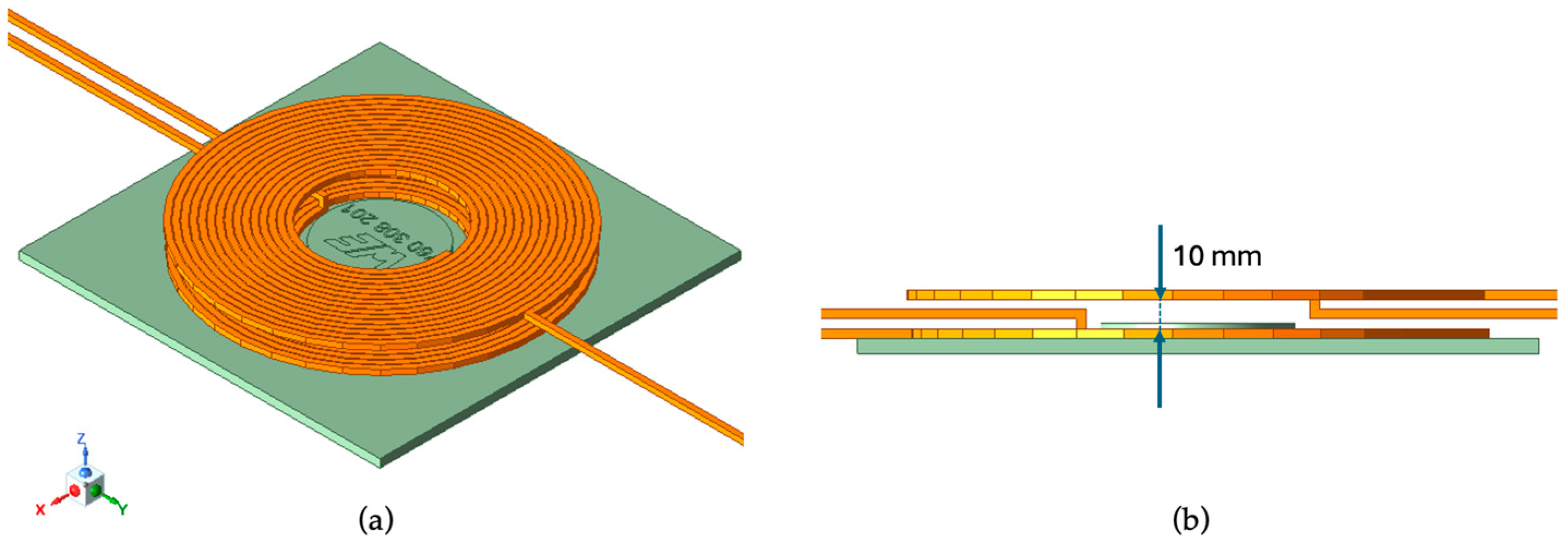
Figure 2 presents an example of the WPT system formed by two litz-wire coils called BL-BL that are separated by a vertical distance of 10 mm. Table 3 summarizes the baseline WPT performance of the investigated coil pair with 10 mm separation.
For large coils, the mutual inductance remains approximately constant (~2.2 µH), indicating that conductor technology has a limited influence on coupling at this scale. In contrast, for smaller coils, planar–planar configurations exhibit higher mutual inductance but significantly increased losses, which offset the coupling advantage. Cross-technology cases show that the receiver-side geometry plays a dominant role in flux capture, as higher mutual inductance is consistently observed when the receiver is planar. However, the coupling coefficient decreases with miniaturization due to reduced effective area. Baseline losses correspond to transmitter-side ohmic losses, as the receiver coil remains unexcited. Figure 3 presents the magnetic field intensity distribution for the BL-BL WPT system.

3.3. Gap Robustness Analysis

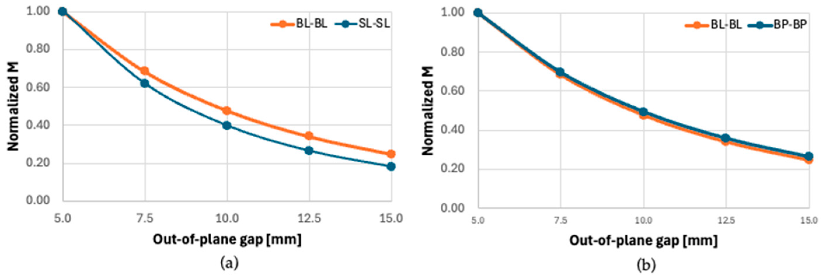
Gap robustness was evaluated by sweeping the out-of-plane separation from 5 mm to 15 mm. Figure 3a compares the miniaturization effect for litz-wire coil pairs (BL-BL and SL-SL) while Figure 3b compares the technology effect for large scale coils (BL-BL and BP-BP).
In Figure 3a, the normalized mutual inductance decreases with increasing separation for both configurations, but the large-scale pair consistently maintains higher values, indicating that it has improved robustness due to its larger effective area and stronger flux linkage. In Figure 3b, litz-wire and planar large-scale configurations exhibit nearly identical trends, indicating that conductor technology has a limited impact on gap robustness at this scale. Although the planar configuration shows slightly higher values, the difference remains minor, confirming that geometric scale dominates gap sensitivity, while technology-related effects are secondary.

3.4. Efficiency Impact of Receiver-Side Ferrite

This section evaluated the impact of receiver-side ferrite on magnetic coupling, and quality factor. The simulation results are stored in Table 4.
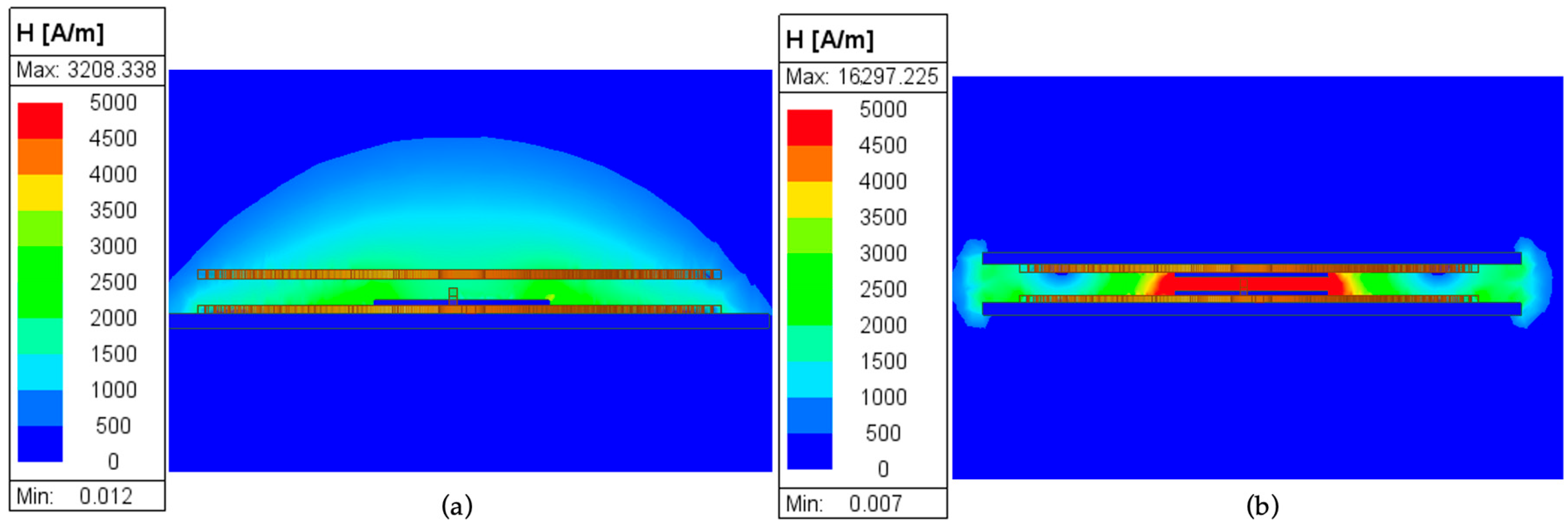
Figure 4 illustrates the magnetic field distribution for the BL–BL WPT system with different ferrite configurations.
Receiver-side ferrite increases both mutual inductance and the coupling coefficient across all configurations, confirming enhanced magnetic flux linkage. The magnetic field distribution shows an improved flux concentration between the coils and reduced leakage into the surrounding air due to the high permeability of the ferrite material. However, the improvement in the quality factor remains limited, particularly for planar coils, where AC losses dominate. While litz-wire coils benefit more significantly from ferrite inclusion, planar implementations exhibit only marginal Q improvement, indicating that conductor losses remain the primary limitation for overall efficiency.

3.5. Footprint-Matched Geometry: AC-Loss Penalty and Mitigation

This section compares litz-wire and planar coils under footprint-matched conditions to isolate conductor-related effects on AC resistance and losses. Table 5 presents the results obtained.
Under footprint-matched conditions, the planar coil exhibits a significant AC-loss penalty compared to the litz-wire baseline, with an approximately six times greater increase in resistance leading to substantially higher losses and reduced Q. Increasing the copper thickness from 35 µm to 70 µm reduces resistance and losses by approximately 50%, while inductivity remains unchanged. This confirms that performance differences are dominated by conductor-related AC losses rather than inductance variations.

4. Conclusions

This paper presented a systematic electromagnetic comparison between litz-wire and planar coil technologies for inductive wireless power transfer. The results demonstrate that planar coils can achieve mutual inductance and coupling coefficients comparable to litz-wire coils under controlled geometric conditions. However, coil miniaturization consistently reduces coupling robustness across all configurations. A key outcome of this study is that coupling-related metrics alone are insufficient to assess WPT coil performance. Although planar coils can provide competitive coupling, particularly when implemented on the receiver side, their efficiency related performance is strongly influenced by conduction losses. Under footprint-matched conditions, planar implementations exhibit a significant AC-loss penalty, primarily driven by increased conductor resistance rather than inductance mismatch. A basic planar-specific mitigation strategy consisting of increased copper thickness was shown to reduce losses and improve quality factor without altering the footprint. Nevertheless, under the investigated conditions, litz-wire coils remain advantageous in efficiency-critical applications. Planar coils, on the other hand, offer integration and manufacturing benefits and their performance can improve when appropriate loss-mitigation strategies are applied.

Author Contributions

Conceptualization, L.P. and C.P.; methodology, L.P. and C.P.; software, L.P.; validation C.C., A.G. and M.G.; formal analysis, L.P.; investigation, L.P.; resources, C.P.; data curation, L.P., C.P. and M.G.; writing—original draft preparation, L.P.; writing—review and editing, C.P.; visualization, C.C., A.G. and M.G.; supervision, C.P., C.C. and A.G.; project administration, C.P.; funding acquisition, C.P. All authors have read and agreed to the published version of the manuscript.

Funding

This research was funded by the Technical University of Cluj-Napoca. No grant number is associated with this funding.

Institutional Review Board Statement

Not applicable.

Informed Consent Statement

Not applicable.

Data Availability Statement

Data are contained within the article.

Acknowledgments

The authors gratefully acknowledge the administrative and technical support provided by the Technical University of Cluj-Napoca (TUCN) for this work.

Conflicts of Interest

The authors declare no conflicts of interest.

References

  1. Kurs, A.; Karalis, A.; Moffatt, R.; Joannopoulos, J.D.; Fisher, P.; Soljacic, M. Wireless Power Transfer via Strongly Coupled Magnetic Resonances. Science 2007, 317, 83–86. [Google Scholar] [CrossRef] [PubMed]
  2. Okoyeigbo, O.; Olajube, A.; Shobayo, O.; Aligbe, A.; Ibhaze, A. Wireless power transfer: A review. IOP Conf. Ser. Earth Environ. Sci. 2021, 655, 012032. [Google Scholar] [CrossRef]
  3. Mohan, S.S.; del Mar Hershenson, M.; Boyd, S.P.; Lee, T.H. Simple accurate expressions for planar spiral inductances. IEEE J. Solid-State Circuits 1999, 34, 1419–1424. [Google Scholar] [CrossRef]
  4. Venkatesan, M.; Rajamanickam, N.; Vishnuram, P.; Bajaj, M.; Blazek, V.; Prokop, L.; Misak, S. A Review of Compensation Topologies and Control Techniques of Bidirectional Wireless Power Transfer Systems for Electric Vehicle Applications. Energies 2022, 15, 7816. [Google Scholar] [CrossRef]
  5. Foote, A.; Costinett, D.; Kusch, R.; Mohammad, M.; Onar, O. Fourier Analysis and Design of a Shielded 120kW Inductive Wireless System. IEEE Trans. Power Electron. 2024, 39, 15295–15314. [Google Scholar] [CrossRef]
  6. Awuah, C.M.; Danuor, P.; Moon, J.-I.; Jung, Y.-B. Novel coil design and analysis for high-power wireless power transfer with enhanced Q-factor. Sci. Rep. 2023, 13, 4187. [Google Scholar] [CrossRef] [PubMed]
  7. Thiagarajan, K.; Deepa, T.; Mahalingam, P. Multi-objective hybrid optimized coil design for enhanced efficiency, improved voltage gain, and compactness for inductive power transfer. Sci. Rep. 2025, 15, 32242. [Google Scholar] [CrossRef] [PubMed]
  8. Munsi, A.; Pradhan, S.; Aditya, K. Advancements in Inductive Wireless Power Transfer: A Comprehensive Review. Chin. J. Electr. Eng. 2025, 11, 75–101. [Google Scholar] [CrossRef]
  9. Ullah, M.A.; Keshavarz, R.; Abolhasan, M.; Lipman, J.; Esselle, K.P.; Shariati, N. A Review on Antenna Technologies for Ambient RF Energy Harvesting and Wireless Power Transfer: Designs, Challenges and Applications. IEEE Access 2022, 10, 17231–17267. [Google Scholar] [CrossRef]
  10. Pacurar, C.; Topa, V.; Constantinescu, C.; Munteanu, C.; Gliga, M.; Andreica, S.; Giurgiuman, A. Adapting the Formula for Planar Spiral Inductors’ Inductance Computation to the New Oval Geometric Shape, Ideal for Designing Wireless Power Transfer Systems for Smart Devices. Mathematics 2025, 13, 348. [Google Scholar] [CrossRef]
  11. Varghese, B.J.; Bobba, P.B.; Kavitha, M. Effects of coil misalignment in a four coil implantable wireless power transfer system. In Proceedings of the 2016 IEEE 7th Power India International Conference (PIICON), Bikaner, India, 25–27 November 2016; pp. 1–6. [Google Scholar] [CrossRef]
  12. Li, S.; Yang, F.; Huang, Y.; Zhao, H. Comprehensive investigation on misalignment tolerance of inductive power transfer systems. Energy Rep. 2023, 9, 1578–1587. [Google Scholar] [CrossRef]
  13. Yang, F.; Liu, Y.; Han, Y.; Chen, J.; Cheng, S.; Tian, Z.; Zhao, H. Misalignment Tolerance Improvement for Loosely Coupled Transformer of IPT Systems via an Intermediate Coil with Detuned Compensation. IEEE Access 2023, 11, 90181–90189. [Google Scholar] [CrossRef]
  14. Luo, J.; Xue, R.; Cheong, J.; Zhang, X.; Yao, L. Design and Optimization of Planar Spiral Coils for Powering Implantable Neural Recording Microsystem. Micromachines 2023, 14, 1221. [Google Scholar] [CrossRef] [PubMed]
  15. Sullivan, C.R.; Zhang, R.Y. Simplified design method for litz wire. In Proceedings of the 2014 IEEE Applied Power Electronics Conference and Exposition—APEC 2014, Fort Worth, TX, USA, 16–20 March 2014; pp. 2667–2674. [Google Scholar] [CrossRef]
  16. Petrascu, L.; Giurgiuman, A.; Constantinescu, C.; Păcurar, C. Coil Modeling Approaches for the Electromagnetic Performance of Wireless Power Transfer Systems. In Proceedings of the 2025 14th International Symposium on Advanced Topics in Electrical Engineering (ATEE), Bucharest, Romania, 9–11 October 2025; p. 6. [Google Scholar] [CrossRef]
Figure 1. Magnetic field distribution of (a) BL; (b) SL.
Engproc 148 00023 g001
Figure 2. Example of BL-BL WPT system: (a) three-dimensional model; (b) cross-sectional view showing the 10 mm out-of-plane separation. The orange color represents the copper windings, while the green color represents the FR-4 substrate.
Engproc 148 00023 g002
Figure 3. Normalized mutual inductance for: (a) miniaturization effect; (b) technology effect.
Engproc 148 00023 g003
Figure 4. Magnetic field distribution for BL-BL system: (a) ferrite in Tx; (b) ferrite in Tx and Rx.
Engproc 148 00023 g004
Table 1. Geometrical properties of coil configurations.
Coil DesignatorBLSLBPSP
Outer diameter [mm]30.122.031.424.0
Inner diameter [mm]12.412.212.412.2
Conductor thickness [mm]0.500.150.0350.035
Conductor width [mm]0.500.150.500.15
Turns spacing [mm]0.100.100.100.10
Number of turns15201624
Table 2. Single-coil electromagnetic performance evaluation.
Coil DesignatorL [μH]Rac [Ω]QLoss [W]
BL9.780.1744.020.09
SL17.920.8816.010.44
BP9.191.146.340.57
SP18.434.683.092.34
Table 3. WPT system electromagnetic performance.
Coil DesignatorM [μH]kL (Tx) [μH]L (Rx) [μH]Loss [W]
BL-BL2.180.309.795.360.09
SL-SL2.320.1817.919.170.44
BP-BP2.170.299.186.270.57
SP-SP2.840.1818.4213.322.34
BL-BP2.390.309.786.360.09
BP-BL1.980.289.195.280.57
SL-SP2.920.1917.9013.430.44
SP-SL2.230.1718.429.092.34
Table 4. Analysis of ferrite inclusion behavior.
Coil DesignatorFerrite InclusionM [μH]kQ (Tx)Q (Rx)
BL-BLTx only2.180.3041.1440.86
BP-BPTx only2.170.296.324.33
BL-BLTx and Rx4.190.3941.9645.68
BP-BPTx and Rx3.320.356.616.63
Table 5. Geometry-matched coil comparison.
Coil DesignatorL
[μH]
R
[Ω]
Loss
[W]
Q
BL9.780.170.0944.02
BP (35 µm)8.001.050.526.02
BP (70 µm)8.000.570.2811.10
Disclaimer/Publisher’s Note: The statements, opinions and data contained in all publications are solely those of the individual author(s) and contributor(s) and not of MDPI and/or the editor(s). MDPI and/or the editor(s) disclaim responsibility for any injury to people or property resulting from any ideas, methods, instructions or products referred to in the content.