


Abstract
Waste heat from gas engine exhaust contains significant thermal energy that can be recovered to improve power plant performance. This study evaluates an Organic Rankine Cycle (ORC) system for waste heat recovery from the exhaust gas of PLTMG Sei Gelam using Aspen HYSYS simulation. A 3E analysis, consisting of energy, exergy, and environmental assessment, was conducted to compare four working fluids: Butane, Pentane, Hexane, and Toluene. Two operating simulations were investigated. In Simulation 1, the exhaust gas outlet temperature was fixed at 150 °C, while the evaporation temperature was varied from 100 °C to 140 °C. In Simulation 2, the evaporation temperature was maintained 15 °C below the exhaust outlet temperature, with exhaust outlet temperature varied from 145 °C to 165 °C. The results show that increasing the evaporation temperature improves the ORC net power output, thermal efficiency, and exergy efficiency, while reducing total exergy destruction. Among the evaluated fluids, Toluene provided the best overall performance in both simulations. In Simulation 1, Toluene achieved the highest net power of 618.57 kW, thermal efficiency of 15.68%, and exergy efficiency of 35.72%, with the lowest total exergy destruction of 1005.11 kW. In Simulation 2, Toluene also produced the highest net power of 618.86 kW, thermal efficiency of 16.74%, and exergy efficiency of 37.38%, with the lowest exergy destruction of 936.70 kW. From the environmental perspective, Toluene showed the highest fuel saving and CO2 reduction potential, reaching 0.01281 kg/kWh and 0.03336 kg CO2/kWh, respectively. Overall, the combined 3E analysis indicates that Toluene is the most suitable working fluid for ORC-based waste heat recovery at PLTMG Sei Gelam, followed by Hexane, Pentane, and Butane.
1. Introduction
Gas engine power plants reject a considerable amount of thermal energy through exhaust gas. This unused heat represents a potential energy source that can be recovered to generate additional power without increasing fuel consumption. Waste heat recovery is therefore an important strategy for improving plant efficiency and reducing environmental emissions. The Organic Rankine Cycle (ORC) is one of the promising technologies for recovering low- to medium-temperature heat sources because it uses organic working fluids with lower boiling points than water. Kaska highlighted that ORC offers flexibility for moderate-temperature heat sources and can convert low-grade heat into useful power [1]. However, the performance of an ORC system strongly depends on the working fluid, operating temperature, heat-source characteristics, and thermodynamic constraints.
Previous studies have demonstrated the potential of ORC systems for engine exhaust waste heat recovery. Srinivasan et al. investigated ORC-based exhaust waste heat recovery from an internal combustion engine and reported improvements in fuel conversion efficiency and reductions in specific NOx and CO2 emissions [2]. Nawi et al. also showed that exhaust waste heat from engine-based power systems can be utilized by ORC systems to improve efficiency and reduce fuel consumption [3]. In addition, Shalaby et al. emphasized that working-fluid selection is an important factor affecting ORC performance, particularly because boiling and critical temperatures determine the suitable operating range of each fluid [4].
Recent studies have further expanded ORC research toward advanced configurations, working-fluid screening, and integrated performance assessment. Sprouse reviewed ORC applications for internal combustion engine waste heat recovery and highlighted the continued development of ORC technology in the latest decade [5]. Sun and Peng experimentally investigated steady-state ORC operation under different operating conditions and showed that operating parameters and working-fluid characteristics strongly influence system performance [6]. Rahaman et al. compared basic, reheat, and regenerative ORC configurations using low-GWP refrigerants and showed that both working-fluid selection and cycle architecture significantly affect energy and exergy performance [7].
Javed and Tiwari compared basic, recuperative, and regenerative ORC configurations using Aspen Plus and reported that regenerative ORC with Toluene provided the best thermal performance among the evaluated fluids and configurations [8]. Integrated energy, exergy, and environmental assessment has been widely used to evaluate ORC system performance and to identify the main thermodynamic and environmental benefits of the system [9]. Techno-economic evaluation of low-GWP working fluids has also been investigated to assess the feasibility of ORC systems for practical waste heat utilization [10]. In addition, ORC systems have been shown to reduce energy consumption and gas emissions in industrial waste heat recovery applications [11].
Although advanced ORC configurations and 4E assessment frameworks have been widely discussed in the literature, application-specific studies using actual gas engine exhaust data from Indonesian gas engine power plants remain limited. In particular, limited studies have evaluated ORC-based waste heat recovery from gas engine exhaust using an integrated energy, exergy, and environmental assessment for working-fluid comparison. Therefore, the present study focuses on a basic ORC configuration as an initial 3E performance screening for PLTMG Sei Gelam. The contribution of this study is the application-specific 3E screening of selected dry organic working fluids for ORC-based waste heat recovery using actual gas engine exhaust data from PLTMG Sei Gelam and Aspen HYSYS simulation.
This study performs a 3E analysis, consisting of energy, exergy, and environmental assessment, of an ORC system for waste heat recovery from gas engine exhaust. Four working fluids, namely Butane, Pentane, Hexane, and Toluene, are evaluated under two operating simulations. The scope of this proceeding paper is limited to a basic ORC system and an indirect environmental assessment based on fuel saving and CO2 reduction. Advanced ORC configurations, detailed economic analysis, working-fluid leakage assessment, and life-cycle carbon footprint evaluation are recommended for future work.
2. Methodology
2.1. Simulation Model
This study investigates the performance of an Organic Rankine Cycle (ORC) system utilizing waste heat from gas engine exhaust at PLTMG Sei Gelam. The system is designed to recover thermal energy from exhaust gases and convert it into useful power through an ORC configuration. The main exhaust gas parameters used in the simulation are presented in Table 1.
Table 1.
Parameters of the gas engine exhaust gas.
The simulation procedure began with the collection of operational data from gas engine exhaust, including exhaust gas temperature, mass flow rate, and pressure. Following the data collection stage, the ORC system model is developed using Aspen HYSYS V14.
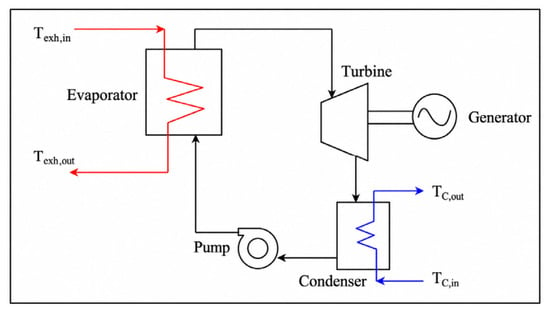
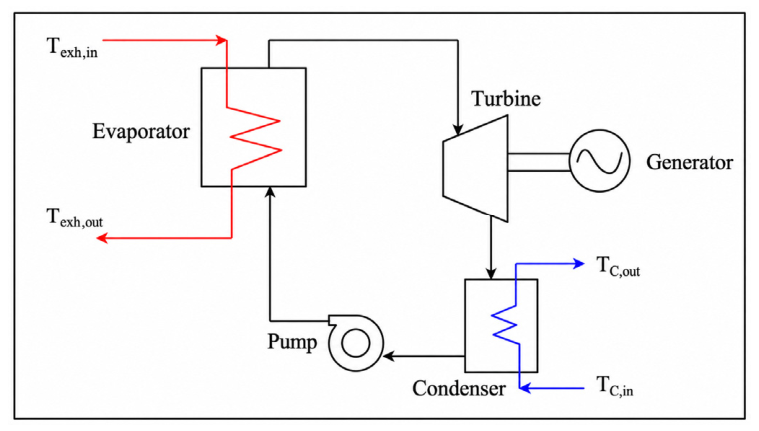
The basic ORC configuration used for gas engine exhaust waste heat recovery is shown in Figure 1. The ORC system consists of four main components: an evaporator, turbine, condenser, and pump. After the model is established, different working fluids are introduced into the system to evaluate their performance. The selected fluids are simulated under identical operating conditions to enable a fair comparison.
Figure 1.
Basic diagram of ORC for gas engine exhaust waste heat recovery [3].
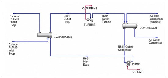
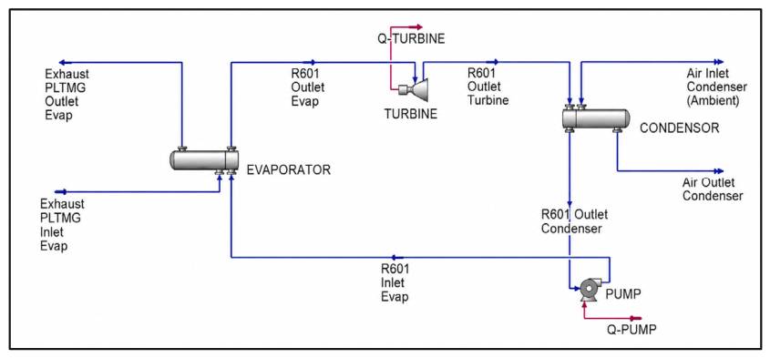
The Aspen HYSYS V14 simulation model of the ORC system is shown in Figure 2. The simulation focuses on a basic ORC configuration, with an additional evaluation of system performance based on different working fluids. The gas engine exhaust is treated as a steady heat source with defined temperature and mass flow rate based on operational data.
Figure 2.
Schematic diagram of the ORC system in Aspen HYSYS.
The evaporator and condenser were defined using specified temperature boundary conditions. In the evaporator, the gas engine exhaust was used as the heat source with an inlet temperature of 380 °C. In Simulation 1, the exhaust gas outlet temperature was fixed at 150 °C, while the evaporation temperature was varied from 100 °C to 140 °C. In Simulation 2, the evaporation temperature was constrained by a temperature approach of 15 °C below the exhaust gas outlet temperature. This temperature approach was applied to maintain a reasonable temperature difference for heat transfer between the exhaust gas and the working fluid.
The condenser was modeled using air as the cooling medium. The cooling air inlet and outlet temperatures were set at 30 °C and 40 °C, respectively, while the working-fluid condensation temperature was maintained at 50 °C. These boundary conditions provide a temperature difference between the condensing working fluid and the cooling air outlet, allowing heat rejection from the working fluid to the air-cooled condenser. Pressure drops in the evaporator, condenser, turbine, pump, and connecting lines were neglected, and heat losses to the surroundings were assumed negligible.
The simulation is conducted under steady-state conditions with the following assumptions:
- Steady-state operation;
- Negligible heat loss to surroundings;
- Pressure drops in all components were neglected;
- Turbine and pump efficiencies are assumed constant.
The simulation was performed iteratively until convergence was achieved, indicating that the mass and energy balances were satisfied and the thermodynamic properties were physically reasonable.
2.2. Working-Fluid Selection
In this study, four different working fluids are considered, namely Butane, Hexane, Pentane, and Toluene. All selected working fluids are classified as dry fluids. This characteristic is important for ORC applications because dry fluids tend to remain in the superheated vapor region after turbine expansion. This reduces the possibility of wet expansion and liquid droplet formation at the turbine outlet. Therefore, the selected fluids are considered suitable for the investigated ORC operating conditions.
The selected working fluids were evaluated under the operating conditions defined in Table 2. Their thermophysical properties are summarized in Table 3. The operating pressure, mass flow rate, and thermodynamic properties were obtained from the Aspen HYSYS database based on the selected working fluid and simulation convergence.
Table 2.
Main operating conditions.
Table 3.
The thermophysical properties of the selected working fluids.
2.3. Energy Calculation Method
Energy analysis in this study is conducted based on the First Law of Thermodynamics, which focuses on the conservation of energy within the system. This analysis is used to quantify the amount of heat absorbed, work produced, and overall energy conversion efficiency of the Organic Rankine Cycle (ORC) system. The turbine work represents the main output of the ORC system and is calculated based on the enthalpy difference of the working fluid between the inlet and outlet of the turbine, as expressed in Equation (1):
The pump work, which represents the energy required to circulate the working fluid within the cycle, is calculated using Equation (2):
2.4. Exergy Calculation Method
Exergy analysis is performed to evaluate the quality of energy conversion and to identify the sources of irreversibility within the system. This approach is particularly important in waste heat recovery systems such as ORC, where not all available energy can be fully converted into useful work due to thermodynamic limitations. The dead-state condition used for the exergy calculation was defined based on the ambient condition, with T0 = 30 °C and P0 = 101.325 kPa. These values were used as the environmental reference state for calculating the specific exergy of the working fluid, exhaust gas, and cooling air streams. The specific exergy of a fluid stream is defined as the maximum useful work that can be obtained as the system comes into equilibrium with the surrounding environment. It is expressed as given in Equation (5):
In addition to efficiency, exergy destruction is also an important parameter in evaluating system performance. Exergy destruction occurs due to irreversibilities such as heat transfer across finite temperature differences, fluid friction, and non-ideal expansion or compression processes [1]. The component exergy destruction equations were formulated based on the exergy balance for each ORC component, including the pump, evaporator, turbine, and condenser. The exergy destruction equations used for each ORC component are summarized in Table 4.
Table 4.
Summary of exergy destruction equations for ORC components.
The exergy efficiency of the ORC system is defined as the ratio of the net work output to the total exergy input from the heat source, as shown in Equation (6):
2.5. Environmental Calculation Method
The environmental analysis is performed to estimate fuel saving and CO2 emission reduction due to the additional power generated by the ORC system. The net power generated by the ORC is assumed to replace part of the electricity that would otherwise be produced by the gas engine power plant.
The reduction in Specific Fuel Consumption (SFC) is used as a key indicator to quantify the fuel-saving potential of the ORC system. It is defined as shown in Equation (7):
The reduction in CO2 emissions is calculated based on the reduced fuel consumption, as expressed in the following Equation (8):
where EFCO2 is the emission factor of the fuel, typically expressed in terms of mass of CO2 per unit of fuel consumed. This relationship shows that the reduction in CO2 emissions is directly proportional to the amount of fuel saved.
The environmental assessment in this study focuses on indirect CO2 emission reduction resulting from fuel saving due to the additional net power generated by the ORC system. Therefore, future studies should include a more complete environmental assessment, such as Total Equivalent Warming Impact (TEWI) or life-cycle carbon footprint analysis, to account for both indirect CO2 reduction and direct emissions from working-fluid leakage.
3. Results and Discussion
3.1. Model Validation
The developed ORC simulation model was validated by comparing its results with published data from Shalaby et al. [4] using similar operating conditions. To ensure a fair comparison, the same working fluid, namely Toluene, was selected following the reference study. In addition, both studies employed Aspen-based simulation, which further ensures consistency in thermodynamic property calculations and the modeling approach. The validation results of the ORC simulation model compared with the reference data from Shalaby et al. [4] are presented in Table 5.
Table 5.
Comparison of simulation results with reference data for model validation.
The validation results show good agreement between the present simulation and the reference data. Most parameters show deviations below 5%, including heat input, mass flow rate, turbine work, and thermal efficiency. Although pump work shows a high percentage deviation, its absolute value is very small and has negligible influence on the overall ORC performance. Therefore, the developed model is considered reliable for further parametric analysis.
3.2. Energy Analysis
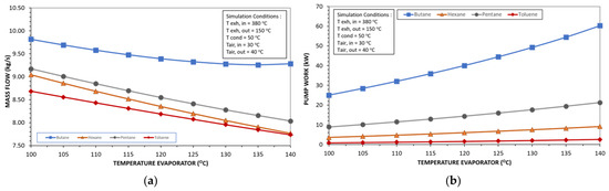
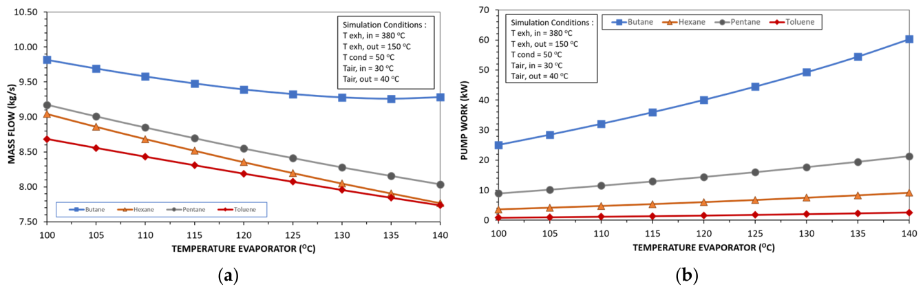
The relationship between mass flow and turbine work as a function of evaporator temperature is presented in Figure 3a,b. The working-fluid mass flow rate decreases as the evaporation temperature increases. Since the evaporator heat input is kept constant, a higher evaporation temperature reduces the required working-fluid flow rate. Pump work increases with increasing evaporation temperature due to the higher evaporator pressure required by the ORC system.
Figure 3.
(a) Effect of evaporator temperature on mass flow rate; (b) effect of evaporator temperature on pump work.
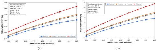
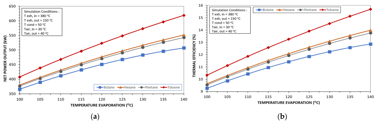
In Figure 4, the net power output increases as the evaporation temperature rises from 100 °C to 140 °C. This improvement is mainly caused by the higher turbine expansion potential at higher evaporator pressure. Although pump work also increases, its effect is smaller than the increase in turbine power. Thermal efficiency increases with increasing evaporation temperature because the evaporator heat input remains constant while the ORC net power output increases.
Figure 4.
(a) Effect of evaporator temperature on net power output; (b) effect of evaporator temperature on thermal efficiency.
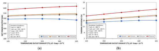
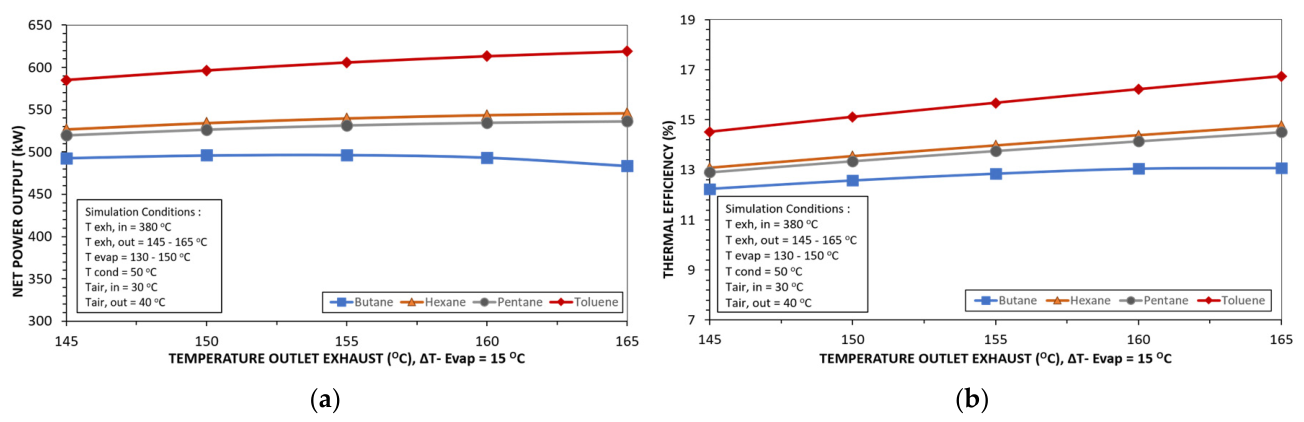
In Simulation 2, the evaporation temperature is maintained 15 °C below the exhaust outlet temperature. As the exhaust outlet temperature increases, the evaporation temperature also increases, leading to a lower required working-fluid mass flow rate. In Figure 5a, the ORC net power output generally increases as the exhaust outlet temperature increases, while maintaining a constant temperature approach of 15 °C. This improvement is mainly caused by the higher evaporation temperature, which enhances turbine expansion potential and increases ORC net power output.
Figure 5.
(a) Effect of exhaust outlet temperature on net power output; (b) effect of exhaust outlet temperature on thermal efficiency.
3.3. Exergy Analysis
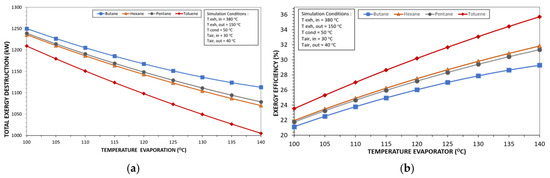
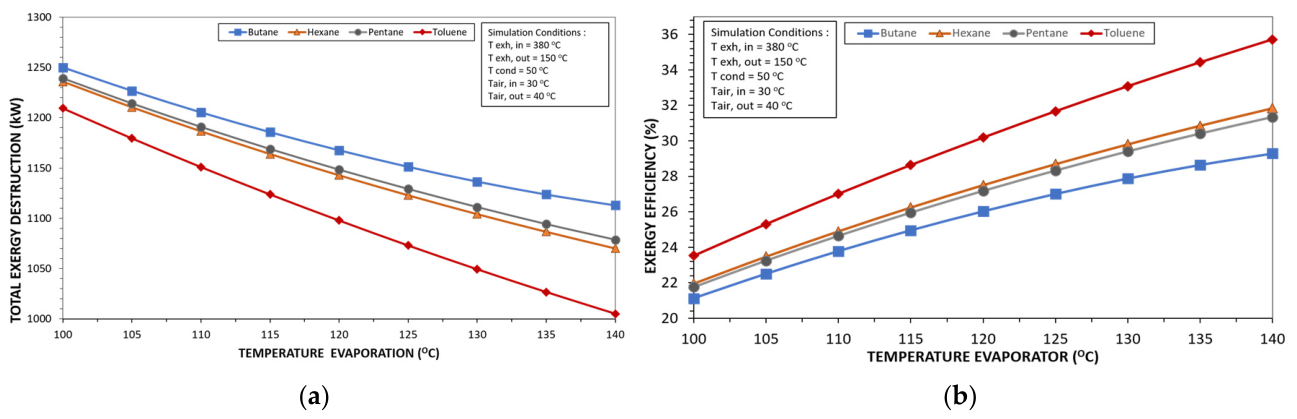
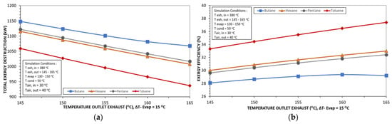
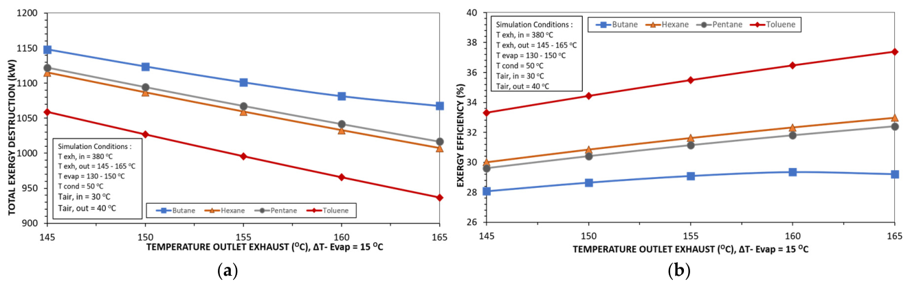
In simulation 1, the total exergy destruction decreases as the evaporation temperature increases, indicating lower system irreversibility at higher evaporation temperatures. This occurs because the heat transfer process between the exhaust gas and the working fluid becomes more effective in terms of exergy utilization. In Figure 6, exergy efficiency increases with evaporation temperature because the ORC system converts a larger portion of the available exhaust heat exergy into useful net power. This improvement is supported by higher turbine expansion potential and lower total exergy destruction at higher evaporation temperatures.
Figure 6.
(a) Effect of evaporator temperature on total exergy destruction; (b) effect of evaporator temperature on exergy efficiency.
In simulation 2, total exergy destruction decreases as the exhaust outlet temperature increases while maintaining a constant temperature approach of 15 °C in Figure 7a. This indicates lower system irreversibility at higher evaporation temperatures. In Figure 7b, exergy efficiency also increases as the exhaust outlet temperature rises. This indicates that the ORC system becomes more effective in converting the available exhaust heat exergy into useful net power. The representative exergy efficiency and exergy destruction values for each ORC component in Simulation 1 are summarized in Table 6.
Figure 7.
(a) Effect of exhaust outlet temperature on total exergy destruction; (b) effect of exhaust outlet temperature on exergy efficiency.
Table 6.
Representative exergy efficiency and exergy destruction components of the cycle in simulation 1.
3.4. Environmental Analysis
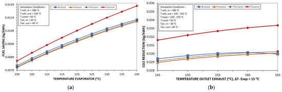
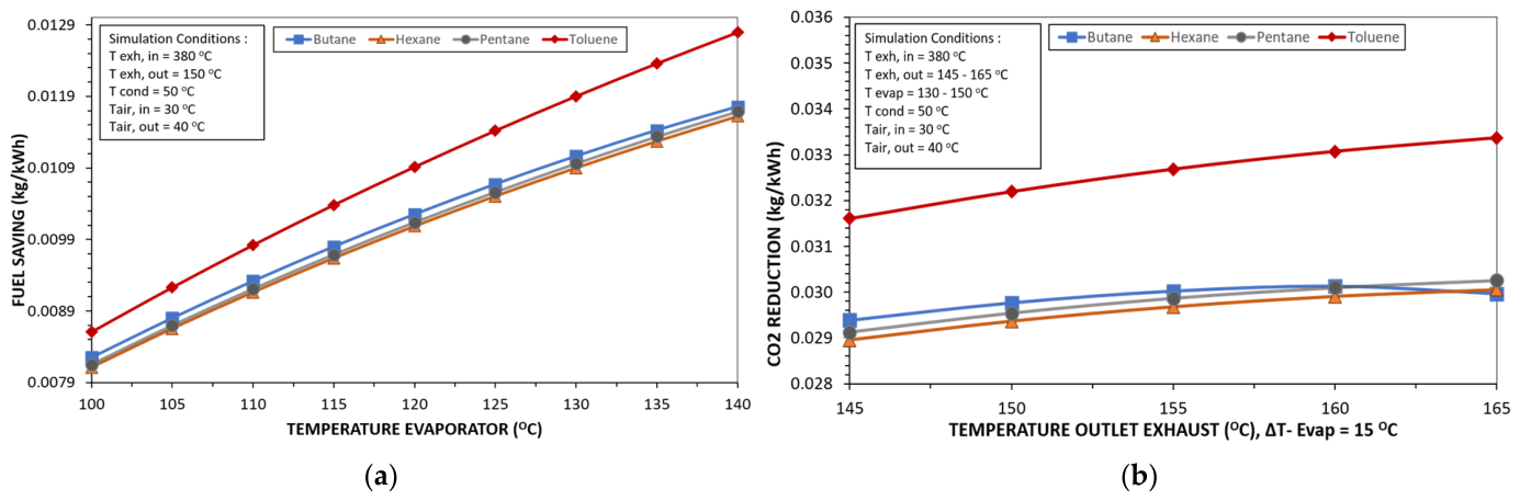
In simulation 1, fuel saving and CO2 reduction increases as the evaporation temperature rises. This trend is mainly driven by the increase in ORC net power output, which provides additional electricity from exhaust waste heat without additional fuel consumption.
Figure 8 shows that fuel saving and CO2 emission reduction increase with ORC net power output. Since the ORC generates additional electricity from exhaust waste heat without additional fuel input, higher net power directly leads to greater fuel saving and emission reduction. Toluene provides the highest environmental benefit because it produces the highest net power among the evaluated working fluids.
Figure 8.
(a) Effect of evaporator temperature on fuel saving; (b) effect of exhaust outlet temperature on CO2 emission reduction.
4. Conclusions
This study provides an application-specific 3E assessment of a basic ORC system for waste heat recovery from PLTMG Sei Gelam gas engine exhaust. The main contribution of this work is the comparative screening of four dry organic working fluids using actual gas engine exhaust parameters and integrated energy, exergy, and environmental indicators. The ORC model was developed using Aspen HYSYS and evaluated under two operating conditions.
Toluene showed the best overall performance in both simulations. In Simulation 1, it produced the highest net power output of 618.57 kW, thermal efficiency of 15.68%, exergy efficiency of 35.72%, and total exergy destruction of 1005.11 kW. In Simulation 2, it achieved 618.86 kW net power output, 16.74% thermal efficiency, 37.38% exergy efficiency, and 936.70 kW total exergy destruction. From the environmental perspective, Toluene also provided the highest fuel saving and CO2 reduction potential. Overall, Toluene was identified as the most suitable working fluid, followed by Hexane, Pentane, and Butane.
The present study is limited to a basic ORC configuration and indirect environmental assessment based on fuel saving. Future work should consider advanced ORC configurations, such as regenerative, dual-pressure, and supercritical ORC systems. In addition, economic analysis, direct working-fluid leakage assessment, GWP-based environmental evaluation, and life-cycle carbon footprint analysis should be included to support practical implementation.
Author Contributions
Conceptualization, A.N. and H.M.A.; methodology, A.N., H.M.A. and R.R.A.; software, A.N.; validation, A.N. and H.M.A.; formal analysis, A.N.; investigation, A.N.; resources, Y.L.; data curation, A.N. and Y.L.; writing—original draft preparation, A.N.; writing—review and editing, H.M.A., R.R.A., K., W.P., M.A.B. and Y.L.; visualization, A.N.; supervision, H.M.A., K., W.P. and M.A.B.; project administration, A.N. All authors have read and agreed to the published version of the manuscript.
Funding
This research received no external funding.
Data Availability Statement
The data presented in this study are available on request from the corresponding author.
Conflicts of Interest
Author Yuda Lestari was employed by the PT PLN Indonesia Power. The remaining authors declare that the research was conducted in the absence of any commercial or financial relationships that could be construed as a potential conflict of interest.
References
- Kaşka, Ö. Energy and exergy analysis of an organic Rankine for power generation from waste heat recovery in steel industry. Energy Convers. Manag. 2014, 77, 108–117. [Google Scholar] [CrossRef] [Scilit]
- Srinivasan, K.K.; Mago, P.J.; Krishnan, S.R. Analysis of exhaust waste heat recovery from a dual fuel low temperature combustion engine using an Organic Rankine Cycle. Energy 2010, 35, 2387–2399. [Google Scholar] [CrossRef] [Scilit]
- Nawi, Z.M.; Kamarudin, S.K.; Abdullah, S.S.; Lam, S.S. The potential of exhaust waste heat recovery (WHR) from marine diesel engines via organic rankine cycle. Energy 2019, 166, 17–31. [Google Scholar] [CrossRef] [Scilit]
- Shalaby, S.M.; Gadalla, M.A.; El Sayed, A.R.; Meliha, E.M.; Abosheiasha, H.F. Aspen Plus simulation of a low capacity organic Rankine cycle heated by solar energy. Energy Rep. 2022, 8, 416–421. [Google Scholar] [CrossRef] [Scilit]
- Sprouse, C.E., III. Review of Organic Rankine Cycles for Internal Combustion Engine Waste Heat Recovery: Latest Decade in Review. Sustainability 2024, 16, 1924. [Google Scholar] [CrossRef] [Scilit]
- Sun, J.; Peng, B. Experimental study on steady-state operation of organic Rankine cycle system under different operating conditions. Sci. Rep. 2025, 15, 1041. [Google Scholar] [CrossRef] [Scilit] [PubMed]
- Rahaman, M.; Islam, M.A.; Miyara, A. Energy and exergy analysis of Organic Rankine Cycles for six low-GWP refrigerants. Next Chem. Eng. 2026, 2, 100021. [Google Scholar] [CrossRef] [Scilit]
- Javed, S.; Tiwari, A.K. Performance assessment of different Organic Rankine Cycle (ORC) configurations driven by solar energy. Process Saf. Environ. Prot. 2023, 171, 655–666. [Google Scholar] [CrossRef] [Scilit]
- Dibazar, S.Y.; Fateh, H.; Khalilarya, S. Energy, exergy, and environmental (3E) analysis of organic Rankine cycle systems: A review. Renew. Sustain. Energy Rev. 2020, 134, 110–121. [Google Scholar]
- Tanbar, F.; Febriyanto, R.; Ariyadi, H.M.; Nugraha, A.D.; Simaremare, A.A.; Supriyanto, E.; Triani, M.; Muflikhun, M.A. Techno-economic studies of low GWP-organic Rankine cycle for low-level geothermal waste heat utilization in Remote Island of Indonesia. Case Stud. Therm. Eng. 2025, 65, 105385. [Google Scholar] [CrossRef] [Scilit]
- Wang, H.; Xu, J.; Yang, X.; Miao, Z.; Yu, C. Organic Rankine cycle saves energy and reduces gas emissions for cement production. Energy 2015, 86, 59–73. [Google Scholar] [CrossRef] [Scilit]

Disclaimer/Publisher’s Note: The statements, opinions and data contained in all publications are solely those of the individual author(s) and contributor(s) and not of MDPI and/or the editor(s). MDPI and/or the editor(s) disclaim responsibility for any injury to people or property resulting from any ideas, methods, instructions or products referred to in the content. |
© 2026 by the authors. Licensee MDPI, Basel, Switzerland. This article is an open access article distributed under the terms and conditions of the Creative Commons Attribution (CC BY) license.