


Abstract
It is essential to exercise control over the environmental impact of deep excavation construction in soft soil areas from the perspective of deformation in order to ensure engineering safety. A three-dimensional finite element model of the foundation pit was developed, thereby creating a comparison between the results of the numerical simulation and the actual on-site monitoring data. This process served to validate the precision of the simulations. The focal point of the study pertained to the three-dimensional effects of support structure deformation and ground settlement during excavation. A comprehensive analysis of the spatial distribution and evolutionary patterns of underground diaphragm wall deformation and ground settlement behind the wall at varying excavation depths was conducted. The results demonstrated that both support structure deformation and ground settlement behind the excavated structure exhibited substantial spatial effects. In particular, larger deformations were observed near the symmetrical plane of the excavation centre. Conversely, greatly smaller deformations were observed in the corners of the excavation. The research findings aim to provide useful references for practical engineering projects.
1. Introduction
With the acceleration of urban renewal processes, construction accidents caused by deformation and damage to adjacent buildings and pipelines due to deep excavation have been frequently reported in recent years [1,2,3,4,5], posing considerable threats to surrounding environmental safety. Due to its superior deformation control, the top-down construction method has been widely adopted [6], drawing attention to the deformation behavior and environmental impact of deep excavations in soft soils.
Studies have shown that in newly filled soft soils, both base heave and surface settlement can develop concurrently, with their magnitudes closely related to excavation depth [7]. As excavation projects grow in scale and complexity, traditional analysis methods struggle to accurately capture deformation patterns, especially in soft or layered soils [8]. In this case, numerical simulation [9,10,11,12] has worked as a key tool due to its predictive accuracy and parameter control. However, for irregular excavation geometries, 2D plane strain models fail to capture three-dimensional effects [13,14,15,16], making 3D finite element modeling essential for realistic deformation prediction and performance-based design [17].
This study is based on a top-down constructed deep excavation project in Nanjing. Field monitoring data during the excavation process were analyzed. A three-dimensional finite element simulation was also conducted in order to investigate the spatial distribution and evolution of the deformation of the retaining structure and the ground settlement at different excavation depths. The results provide valuable reference for similar deep excavation engineering projects.
2. Project Overview
2.1. Project Description
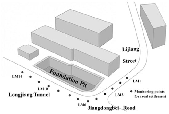
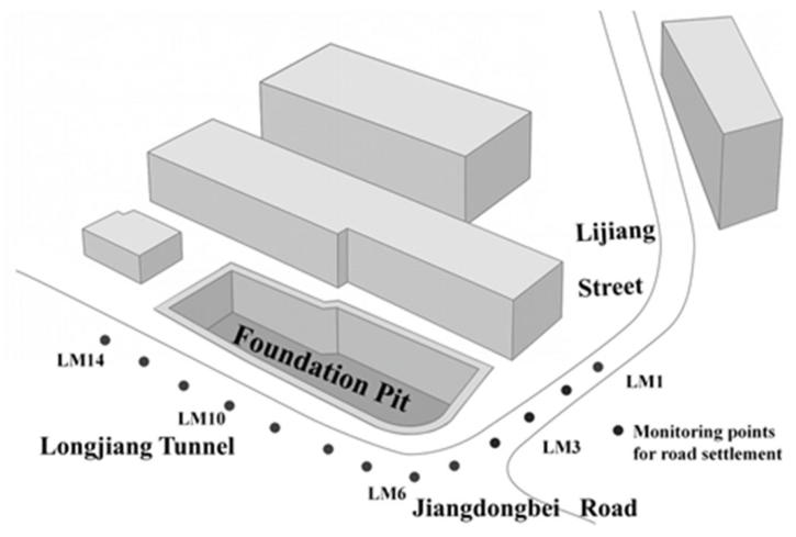
The deep excavation project is located near a major arterial road in downtown Nanjing, covering an area of 12,175 m2 with a perimeter of 510 m. The average excavation depth ranges from approximately 19.4 m to 21.5 m. In order to conduct a comprehensive investigation into the ground settlement induced by deep excavation, a network of monitoring points was carefully established in the surrounding area of the excavation. These points were strategically positioned to record both the settlement of the road surface and that of any surrounding structures. The layout of the site and monitoring points is illustrated in Figure 1.
Figure 1.
Distribution of monitoring points for buildings and road.
The area under consideration for construction is characterised by a mean ground elevation ranging from 5.8 to 6.4 m, with relatively flat terrain, and is situated within the geomorphic unit of the Yangtze River floodplain. The soil layers constituting the retaining walls of the foundation pit predominantly comprise layers ②2 and ②3, which are distinguished by their silty clay composition with improved moisture content, reduced strength, and a propensity towards thixotropic and flow-type failure, thereby impeding excavation stability.
The phreatic aquifer is primarily composed of cohesive soils in Layers ②2 and ②3. The second layer, which is characterised by a substantial groundwater presence, demonstrates a low level of permeability and a reduced yield capacity. Consequently, it is designated as a stratum exhibiting weak permeability. The second layer, which consists of silty clay and clay with thin interbedded silt layers, has been found to have relatively higher permeability and water yield. This layer is therefore categorised as a weakly water-bearing stratum. The confined aquifer at the site corresponds to Layer ②5, which is composed of fine to medium sand. This layer is characterised by its high permeability and good water yield, indicating a well-developed water-bearing formation. Preliminary field investigations conducted as part of the site exploration process have yielded findings that include a stable groundwater level measuring between 2.20 m and 3.20 m below the ground surface.
2.2. Excavation and Construction Procedure
The excavation is surrounded by a diaphragm wall measuring 1000 mm in thickness. This wall functions both as the retaining wall and the basement exterior wall.
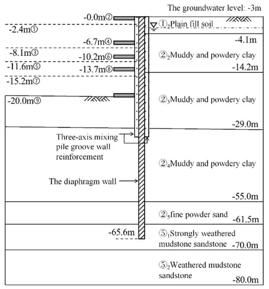
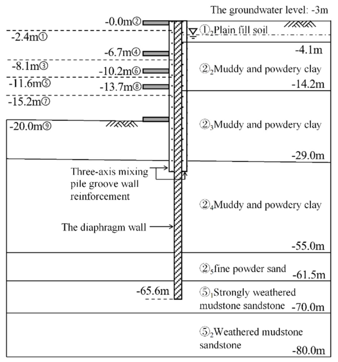
To minimize the impact of excavation on the surrounding environment, triple-shaft mixing piles (φ850 mm @ 600 mm spacing) were constructed on both sides of the diaphragm wall, extending from the ground surface to −31.4 m. The groundwater level was assumed to be at −3.0 m. The construction sequence, soil stratification, and cross-sectional view of the retaining structure are illustrated in Figure 2.
Figure 2.
Section diagram of the supporting structure and construction sequence.
The excavation was carried out using the top-down method in five stages. Stages involved excavation to 2.4 m, 8.1 m,11.6 m, 15.2 m and 20.0 m followed by constructing each floor slab and roof slab layer by layer.
3. Three-Dimensional Finite Element Simulation of Excavation-Induced Deformation
3.1. Establishment of the 3D Finite Element Model
Previous studies [13,14,15,16] have shown that due to the corner arching effect, plane strain models often fail to accurately predict deformation behavior in irregularly shaped excavations. Three-dimensional analysis can better represent actual deformation conditions. In this study, a 3D model was established using the Hardening Soil with Small-Strain Stiffness (HSS) model [18], which accounts for the degradation of shear modulus with strain, compression hardening, and dilatancy in soft clays, making it suitable for simulating deep excavation in complex environments.
Numerical simulations were performed using Plaxis 3D 2024.1, finite element software widely employed in geotechnical engineering. The HSS model was adopted to accurately represent the nonlinear stress–strain behavior and small-strain stiffness degradation of the soil. Initial stresses in the ground were generated using the K0 procedure, ensuring equilibrium conditions consistent with the in situ stress state prior to excavation. The excavation and support process was modeled in five sequential construction stages, with excavation depths reaching 2.4 m, 8.1 m, 11.6 m, 15.2 m, and finally 20.0 m. Following each stage of excavation, the corresponding basement or roof slab was constructed, in order to simulate the progressive installation of horizontal support. This staged construction approach enabled a comprehensive investigation into ground deformation, wall deflection, and the development of internal forces throughout the excavation process.
The HSS model parameters are as follows: The plain fill soil (Layer ①2) has a void ratio of 0.868, cohesion of 3.55 kPa, and friction angle of 33.3°, with moderate stiffness values (e.g., E50ref = 4.34 MPa, G0ref = 84.30 MPa). Muddy and powdery clay (Layers ②2 to ②4) shows similar properties, with void ratios around 1.0, cohesion from 5.79 to 6.39 kPa, and friction angles between 29.86° and 30.62°. Their stiffness parameters are relatively low to moderate (E50ref ≈ 3.38~3.58 MPa; G0ref ≈ 56.55~67.39 MPa). The fine powder sand (Layer ②5) has a lower void ratio (0.834) and higher stiffness (E50ref = 10.17 MPa; G0ref = 107.32 MPa), indicating better mechanical performance. All layers share similar values for γ0.7, m, and Rf, where γ0.7 was between 3.2 × 10⁻⁴ and 3.9 × 10⁻⁴ (except for chalky soils which are slightly higher at 3.9 × 10⁻⁴, and 3.2 × 10⁻⁴), m values were predominantly 0.65 (0.70 for the chalky sandy soils), while Rf was 0.95 for both, suggesting consistent small-strain behavior and failure criteria across layers.
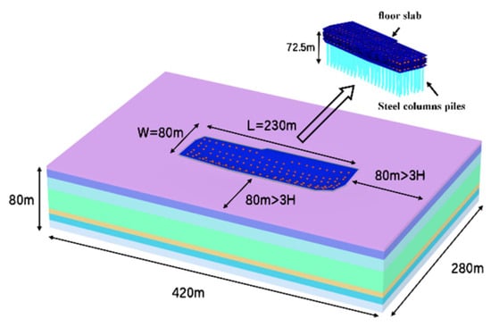
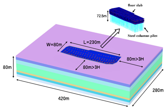
According to Roboski [19], boundary effects become negligible when the model boundary is at least three times the excavation depth. In this study, the excavation depth is 20 m, and the numerical model was constructed with dimensions of 420 m in length, 280 m in width, and 80 m in depth, exceeding four times the excavation depth to minimize boundary effects. The diaphragm wall extends to a depth of 65.6 m, as illustrated in Figure 3. The basement floor slabs provide horizontal support, while the steel columns and column piles provide vertical support.
Figure 3.
Three-dimensional finite element model.
The soil mass is modeled using 10-node tetrahedral elements; continuous walls and floor slabs are represented with slab elements; and steel columns and column piles are simulated using beam elements and embedded beam elements, respectively. The basic model comprises a total of 132,236 soil elements and 210,440 nodes. A refined mesh was applied to the excavation area, the diaphragm wall, and the settlement zone posterior to the wall, while a coarser mesh was utilised at greater distances from the excavation in order to enhance computational efficiency. Sensitivity analysis confirmed that this meshing strategy effectively balances computational accuracy and efficiency, noticeably enhancing overall solution performance.
3.2. Horizontal Deformation of Retaining Structures
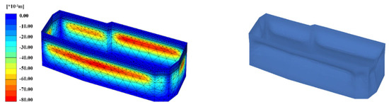
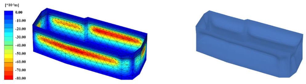
The simulated lateral deformation of the diaphragm wall is shown in Figure 4. An obvious 3D deformation pattern is observed. Greater deformation has been observed to occur in proximity to the central symmetry axis of the excavation in comparison to the corners. This phenomenon can be attributed to the arching effect and the mutual constraint imposed by adjacent walls.
Figure 4.
Deformation nephogram and 3D deformation of the diaphragm wall.
The construction of the floor slab occurred in immediate succession to the excavation reaching a depth of 2.4 m. Consequently, the top of the diaphragm wall experienced minimal displacement, primarily due to the substantial horizontal support provided by the slab. The diaphragm wall exhibited an evident deformational trend, manifested as a spindle-like pattern, with diminished displacements observed at the upper and nethermost points, while pronounced movements were recorded centrally. This phenomenon transpires due to the sequential casting of floor slabs during the top-down construction process, thereby establishing a horizontal support system. The slabs possess high stiffness, effectively limiting the lateral deformation of the diaphragm wall throughout excavation.
Under the combined constraints of the top and bottom slabs, the lateral displacement of the diaphragm wall is mainly concentrated in the middle region, while the displacements at the top and bottom remain relatively small, producing an overall “bulging middle and converging ends” spindle-shaped configuration. This deformation pattern can be interpreted as resulting from the joint influence of the self-stabilising capacity of the structure and the interlayer constraint effect which is intrinsic to the top-down construction method.
As excavation depth increases, maximum deformation also increases. The maximum displacement zone gradually moves downward, but the overall deformation pattern remains consistent. The rigidity of the floor slabs results in limited additional deformation in the upper part of the wall once slabs have been constructed. When the excavation reached 20 m, the maximum lateral displacement was 55.3 mm, with a displacement-to-depth ratio of 0.28%. As the excavation depth increases, the maximum deformation growth rate of the continuous wall slows down. It is evident that with the increase in excavation depth, the structural stiffness of the system, comprising the continuous wall, the column piles, and the horizontal support of the floor, experiences a corresponding increment.
3.3. Surface Settlement Behind the Diaphragm Wall
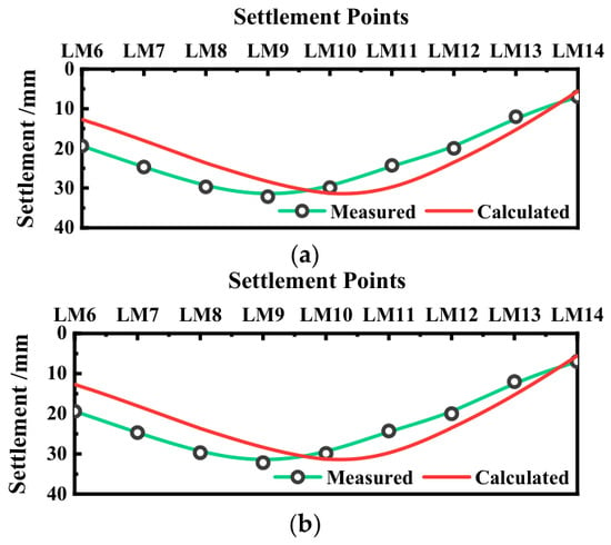
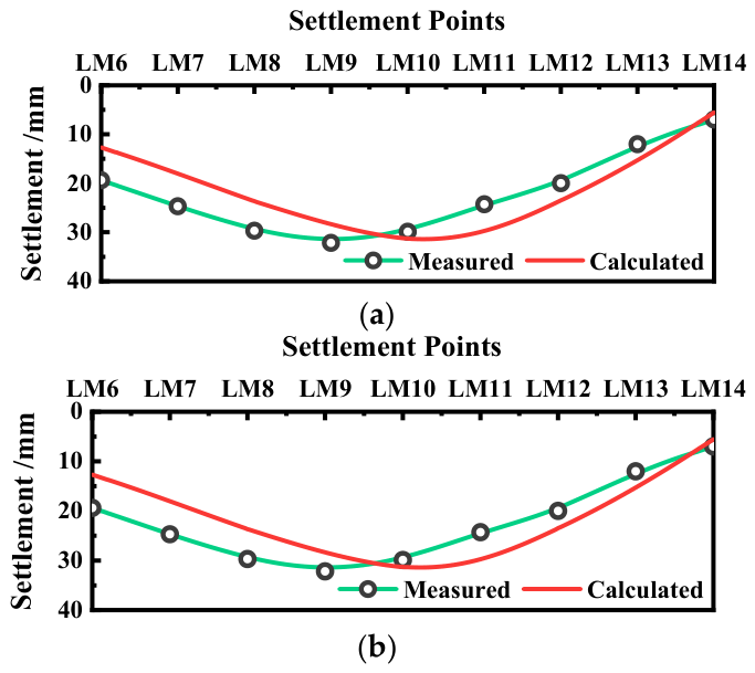
Comparison of the measured and calculated ground surface settlements is shown in Figure 5. Both show good agreement, with the largest settlements occurring near the central monitoring points (LM3-LM4 on the south side and LM9-LM10 on the west side). Monitoring points at the corners (e.g., LM1, LM5, LM6, LM14) recorded greatly smaller settlements, confirming strong spatial deformation patterns for irregular excavations.
Figure 5.
Comparison of the measured and calculated ground surface settlements. (a) South side. (b) West side.
The settlement on the south side of the excavation is generally smaller than that on the west side. The monitoring points exhibiting the greatest settlement on both sides are located in close proximity to the centre of the excavation, exhibiting a slight inclination towards the southwest corner. This suggests the presence of a pronounced spatial effect in the ground surface settlement behind the retaining wall. The larger settlement observed in the southwest corner is related to preliminary construction activities, such as the installation of diaphragm walls and the setting of piles as a foundation for the excavation works.
During the construction of the supporting system, the triple-shaft deep mixing pile reinforcement was initiated along the west side of the excavation, proceeding in a counterclockwise direction. Subsequent to a 72 h period, a secondary triple-shaft mixing rig was initiated to reinforce the inner row along the west side, in immediate succession to the primary rig. Ten days after the initial operation, construction of the guide wall and temporary road commenced, followed by the installation of the diaphragm wall, foundation pile construction, and dewatering well installation. Consequently, the initial indications of settlement were observed along the western and southern periphery of the excavation during the construction phase of the diaphragm wall. In addition, given the location of this area in close proximity to a pedestrian overpass with relatively high surface loading, it was observed that the magnitude of final settlement in the southwest corner was greatly improved.
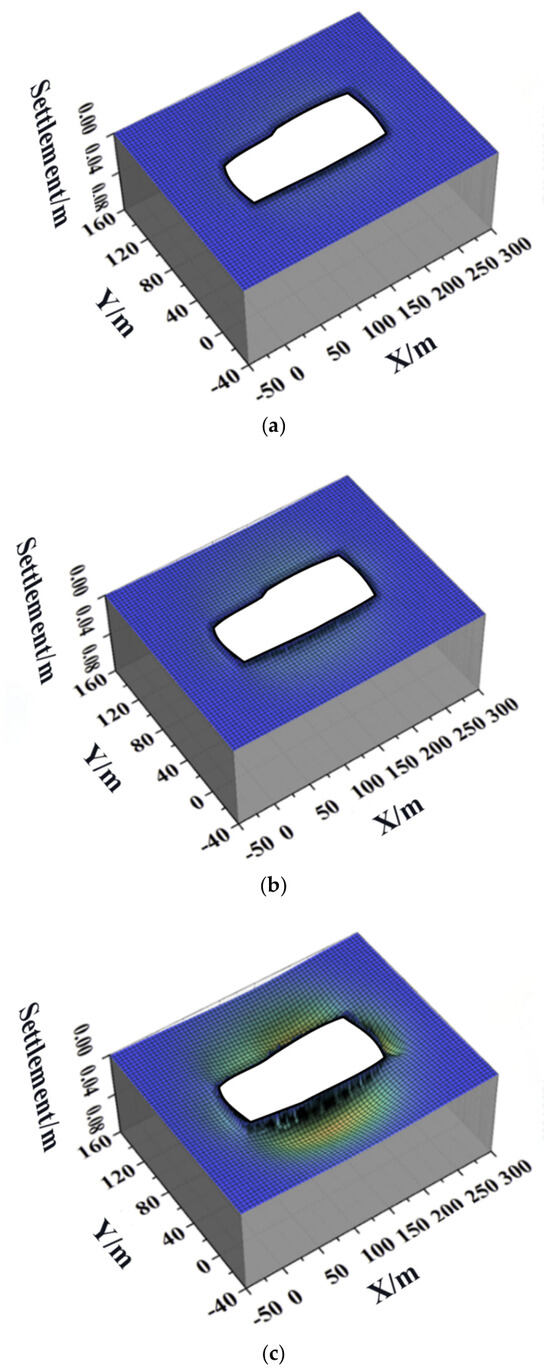
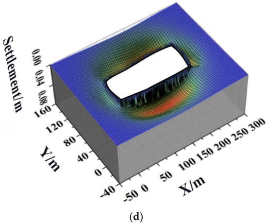
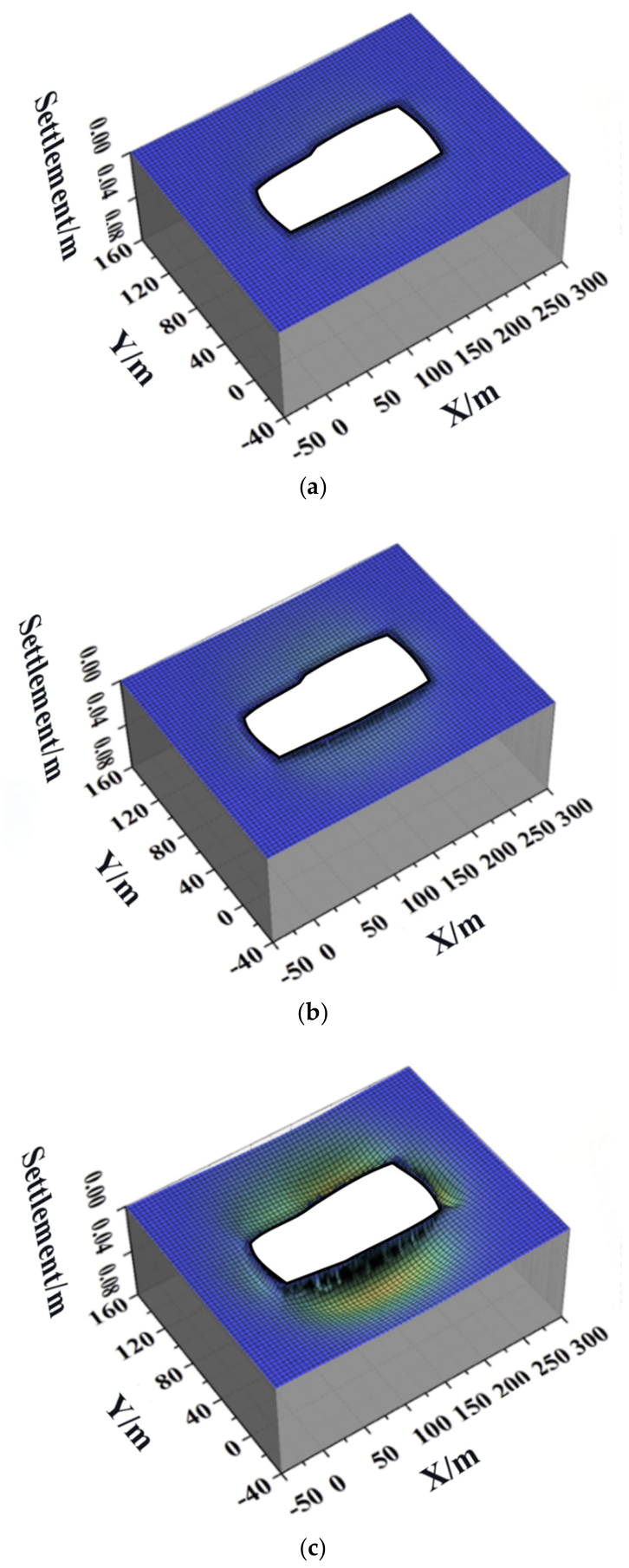
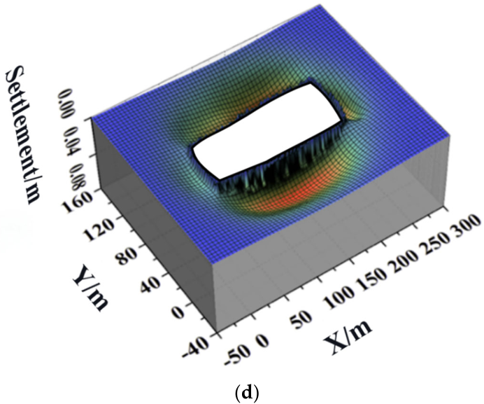
The surface settlement evolution during excavation is illustrated in Figure 6. As excavation depth increases, the magnitude and spatial extent of settlement increase concomitantly. Initial wall displacement typically results in shallow settlement, while subsequent deeper displacements shift the settlement trough farther from the wall. This process generally leads to the formation of a concave settlement profile, with the maximum settlement typically occurring at a distance of approximately 14 metres behind the wall.
Figure 6.
Spatial distribution of surface settlement under different excavation depths. (a) H = 8.1 m. (b) H = 11.6 m. (c) H = 15.2 m. (d) H = 20.0 m.
Settlement development aligns with wall deformation trends. Greater settlement is observed in proximity to the central axis of the excavation, with corners exhibiting remarkably less settlement, suggesting the presence of pronounced spatial effects. Also, the extent of influence increases with excavation depth, exhibiting a wider range in the central area compared to the corners.
It has been demonstrated by simulation that the lateral displacement and surface settlement near the diaphragm wall corners are substantially less than those in the central area, thereby revealing the so-called “Corner-Arch” effect. This phenomenon can be attributed to the rigid connection formed by the two adjacent diaphragm walls at the corner. This connection provides mutual support during deformation, thereby effectively restraining lateral and vertical movements in the region. The concentration of corner stiffness and reduction in force transmission paths contribute to a more stable deformation pattern, resulting in settlement being concentrated near the centre of the excavation, with a concave profile characterised by central subsidence and uplifted corners.
The analysis indicates that the maximum settlement on the west side of the excavation reaches 32.1 mm, which is notably higher than the 22.2 mm observed on the south side. The settlement curve on the west side is found to be steeper, and the influence zone broader. The observed tendency of larger and more extensive settlements to occur along the longer side of the excavation in the absence of support conditions suggests that the presence of such support is a prerequisite for such settlements to occur.
This behavior may be attributed to differences in spatial stress distribution and structural constraint effects. The longitudinal axis of the excavation is more susceptible to the formation of continuous settlement zones, a phenomenon attributable to its greater length and the non-uniform stiffness distribution characteristics within the retaining structure. In addition, construction activities tend to disturb a wider area along the long side, making it more susceptible to flexible deformation. In contrast, the short side, with smaller span, higher overall stiffness, and a more confined disturbance range, exhibits smaller and more gradual settlement deformations.
4. Conclusions
A comprehensive study was conducted to investigate the spatial effects and evolution of deformation in retaining structures and ground surfaces during excavation. This study utilised a combination of field monitoring analysis and 3D numerical simulation techniques to achieve a thorough understanding of the subject. The key findings are as follows:
(1) Both field and simulated results show that diaphragm wall deformation exhibits notable three-dimensional effects. Greater deformations occur near the central symmetry plane, while corners show much smaller displacements. The wall displays a spindle-shaped lateral deformation, characterised by pronounced displacements in the central region and relatively minimal deformations at the superior and inferior regions. With increased excavation depth, the maximum deformation increases and shifts downward, though the overall deformation shape remains stable.
(2) Ground surface settlement increases with excavation depth, and the affected range expands. The settlement profile exhibits a concave shape posterior to the wall, with the maximum subsidence occurring at a specific distance away from the wall. The settlement patterns demonstrate a correlation with the lateral displacement of the wall, exhibiting remarkable spatial variation. The settlement is observed to be greater near the centre of the structure and less pronounced at the corners.
(3) A comparison between measured and simulated values at various excavation stages shows good agreement. Slight deviations at the southwest corner are attributed to pre-excavation activities. The findings of this study substantiate the hypothesis that a three-dimensional finite element model works as an effective tool to predict the deformation of the wall and the surrounding surface settlement.
These findings provide technical reference for the deformation control of deep excavation projects in complex urban environments.
Funding
This research received no external funding.
Institutional Review Board Statement
Not applicable.
Informed Consent Statement
Not applicable.
Data Availability Statement
The original datasets generated during the simulation are fully included within the main text of this article. Further queries regarding the data can be addressed to the corresponding author.
Acknowledgments
During the writing of this manuscript, the author used Chatgpt 5.3 during the Chinese-to-English translation process and for checking grammar. The authors take full responsibility for the use of these tools and take full responsibility for the content of the paper.
Conflicts of Interest
The author declares no conflict of interest.
References
- Yang, T.; Liu, S.; Wang, X.; Zhao, H.; Liu, Y.; Li, Y. Analysis of the deformation law of deep and large foundation pits in soft soil areas. Front. Earth Sci. 2022, 10, 828354. [Google Scholar] [CrossRef] [Scilit]
- Zhu, Q.; Qin, H.; Zhai, L.; Wang, R.; Guo, P.; Lv, X. Deformation Characteristics of a Deep Excavation Supported by a Dual-Purpose Diaphragm Wall in the Yangtze River Floodplain Areas. Int. J. Geomech. 2025, 25, 05025003. [Google Scholar] [CrossRef] [Scilit]
- Huang, Z.; Liu, C.; Zhang, N.; Wang, G.; Yu, F. Impact of deep foundation pit covered-excavation reverse construction in water-rich sand layers on surrounding environment. Urban Mass Transit 2024, 27, 188–195. [Google Scholar] [CrossRef]
- Zhan, S.; Ding, S.; Ren, W.; Wang, L.; Zhao, K. Deformation characterstics of deep excavation with suspended curtain in yangtze river floodplain area with highly confined water. J. Eng. Geol. 2025, 33, 645–655. [Google Scholar] [CrossRef]
- Yang, C.; Luo, Z.; Zhu, J.; Jiang, M.; Li, Y. Deformation analysis and design optimization of thin-walled and ultra-wide ground wall foundation pits. Geotech. Investig. Surv. 2025, 53, 16–21+50. [Google Scholar]
- Li, T.; Liu, B.; Chu, W.; Xuan, L.; Dai, J. Force analysis and control of deep excavation lateral supporting system in Shanghai soft clay area. Geotech. Investig. Surv. 2018, 46, 19–26+60. [Google Scholar]
- Wang, L.; Zhu, C.; Xu, K.; Yu, J.; Lü, X. Numerical simulation of deformation control during excavation of deep foundation pit in soft soil with newly filled soil. Chin. J. Geotech. Eng. 2021, 43, 84–87. [Google Scholar] [CrossRef]
- Song, B.; Qin, H.; Wang, R.; Zhai, L.; Wang, L.; Lü, X. Deformation Control Indicator for Deep Foundation Pit Based on Subway Tunnel Protection Requirements in Nanjing Area. J. Tongji Univ. (Nat. Sci.) 2025, 53, 548–556. [Google Scholar] [CrossRef]
- Dong, Y.P.; Burd, H.J.; Houlsby, G.T. Finite-element analysis of a deep excavation case history. Geotechnique 2016, 66, 1–15. [Google Scholar] [CrossRef] [Scilit]
- Yin, Z.; Jin, R.; Guan, S.; Chen, Z.; Dai, G.; Zhu, W. Research on Construction Sequencing and Deformation Control for Foundation Pit Groups. Appl. Sci. 2025, 15, 7719. [Google Scholar] [CrossRef] [Scilit]
- Guo, C.; Yang, X.; Guo, C.; Li, P. Analysis of Deformation of Deep and Large Foundation Pit Support Structure and Impact on Neighbouring Buildings in Complex Environments. Buildings 2025, 15, 1435. [Google Scholar] [CrossRef] [Scilit]
- Bin-Chen, B.H.; Yang, K.H.; Aila, W.; Hung, C. Three-dimensional effects of a deep excavation on wall deflections in loose to medium dense sands. Comput. Geotech. 2016, 80, 138–151. [Google Scholar] [CrossRef] [Scilit]
- Li, Y.; Zhou, Z.; Alcalá, J.; Yepes, V. Research on spatial deformation monitoring and numerical coupling of deep foundation pit in soft soil. J. Build. Eng. 2025, 99, 111636. [Google Scholar] [CrossRef] [Scilit]
- Lim, A.; Ou, C.Y. Performance and Three-Dimensional Analyses of a Wide Excavation in Soft Soil with Strut-Free Retaining System. Int. J. Geomech. 2018, 18, 05018007. [Google Scholar] [CrossRef] [Scilit]
- Gu, X.-Q.; Wu, R.-T.; Liang, F.-Y.; Gao, G. On HSS model parameters for Shanghai soils with engineering verification. Rock Soil Mech. 2021, 42, 833–845. [Google Scholar] [CrossRef]
- Ou, C.Y.; Shiau, B.Y.; Wang, I.W. Three-dimensional deformation behavior of the Taipei National Enterprise Center (TNEC) excavation case history. Can. Geotech. J. 2000, 37, 438–448. [Google Scholar] [CrossRef]
- Qin, H.; Tian, X.; Wang, R.; Wang, L.; Lü, X.-l. Analysis of Ground Deformation and Response Characteristics of Retaining Structures Induced by Deep Foundation Pit Excavation in the Yangtze River Floodplain Area. Struct. Eng. 2024, 40, 165–171. [Google Scholar] [CrossRef]
- Xv, Z.; Wang, W. Selection of soil constitutive models for numerical analysis of deep excavations in close proximity to sensitive properties. Rock Soil Mech. 2010, 31, 258–264+326. [Google Scholar] [CrossRef]
- Roboski, J.F. Three-Dimensional Performance and Analyses of Deep Excavations; Northwestern University: Evanston, IL, USA, 2004. [Google Scholar] [CrossRef] [Scilit]
Disclaimer/Publisher’s Note: The statements, opinions and data contained in all publications are solely those of the individual author(s) and contributor(s) and not of MDPI and/or the editor(s). MDPI and/or the editor(s) disclaim responsibility for any injury to people or property resulting from any ideas, methods, instructions or products referred to in the content. |
© 2026 by the author. Licensee MDPI, Basel, Switzerland. This article is an open access article distributed under the terms and conditions of the Creative Commons Attribution (CC BY) license.